Posts | Comments

Planet Arduino

Archive for the ‘Practical Arduino’ Category

Hello fellow Arduidans

Today we are going to make a real time clock Arduino shield. If you have been following my tutorials,  in weeks 7, 8 and onwards we have been making use of the Maxim DS1307 real time clock chip. Although it is a very interesting part to use, implementing it has not been so easy, therefore the reason for this shield. So let’s go!

First of all, we need create our circuit diagram. Thankfully the Maxim DS1307 data sheet [pdf] has this basics laid out on page one. From examining a DS1307 board used in the past, the pull-up resistors used were 10k ohm metal films, so I’m sticking with that value. The crystal to use is 32.768 kHz, and thankfully Maxim have written about that as well in their application notes [pdf], even specifying which model to use. Phew!

So here is the circuit diagram we will follow (click on it to enlarge):

Which gives us the following shopping list:

  • One arduino protoshield pack. I like the yellow ones from Freetronics, however others may prefer this one
  • X1 – 32.768 kHz crystal – Citizen America part CFS206. You should probably order a few of these, I broke my first one very quickly…
  • IC1 – Maxim DS1307 real time clock IC
  • 8-pin IC socket
  • CR2032 3v battery
  • CR2032 PCB mount socket
  • R1~R3 – 10k ohm metal film resistors
  • C1 – 0.1 uF ceramic capacitor

And here are our parts, ready for action:

The first thing to do is create the circuit on a solderless breadboard. It is much easier to troubleshoot possible issues before soldering the circuit together. Here is the messy test:

Messy or not, it worked. Instead of writing another sketch, the example 7.3 from arduino tutorial seven was used. Here is a copy: example 7.3.pdf.

The next step is to consider the component placement and wiring for the protoshield. Try not to rush this step, and triple-check your layout against the schematic. As my protoshield has a green and red LED as well, I have wired the square-wave output to the green LED. You can never have too many blinking lights…

At this point I celebrated the union of tea and a biscuit. After returning to the desk, I checked the layout once more, and planned the solder bridges. All set – it was time to solder up. If you have the battery in the holder for some reason, you should remove it now, as they do not like getting warm. Furthermore, that crystal is very fragile, so please solder it in quickly.

And here we are – all soldering done except for the header sockets. At this point I used the continuity function of the multimeter to check the solder joints and make sure nothing was wrong with the circuit.

Final checks passed, so on with the headers. To make this easier, I stick some header pins in the sockets, then place the whole lot in a solderless breadboard to keep it straight. Well, it works for me:

Just a side note – always make sure you have enough consumables, the right tools, etc., before you start a project. This is how much solder I had left afterwards…

Moving on … in with the battery and the DS1307 –  we’re done!

It is now time for the moment of truth – to insert the USB cable and re-run the sketch… and it worked! The blinking LED was too bright for me, so I de-soldered the wire. If you are making a shield, congratulations to you if yours worked as well. If it did not, don’t be afraid to hit me up via email or our Google Group with your questions. Note that if you are using this shield, you cannot use analog pins 4 and 5 – they are being used as the I2C bus. Time to clear up the desk and wash my hands.

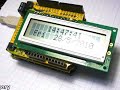
Now to put this shield to work. Last week we made an LCD module shield – so let’s pile up the shields and make a digital clock. We can re-use the sketch from arduino tutorial example 7.4, with the liquidcrystal() corrected to use the LCD shield pins. Here is the modified sketch: ds1307shielddemo.pdf.

And my post wouldn’t be complete without a video, so here are our new shields in action!

So there we have it. Another useful shield, and proof that the Arduino system makes learning easy and fun. High resolution photos are available on flickr. If you have any questions or comments, please leave them below, or consider joining our Google Group!

As always, thank you for reading and I look forward to your comments and so on. Please subscribe using one of the methods at the top-right of this web page to receive updates on new posts!


Hello readers

Today we are going to examine the Freetronics “2010″ (Duemiladieci in Italian). This is a 100% Arduino Duemilanove-compatible board with some very neat enhancements. It was conceived by two Arduino experts here in Australia, Jon Oxer (co-author of the fascinating book “Practical Arduino“) and Marc Alexander. These two gentleman have formed Freetronics to help people build the projects detailed in the Practical Arduino book, assist people in releasing their hardware designs and generally help accelerate the open-source hardware movement. Jon and Marc were recently interviewed about Freetronics and the 2010 by Marcus Schappi, a copy of which can be viewed here.

But for now, back to the 2010. First of all, let’s have a look:

At first glance you may think “oh, just another Arduino clone”. Not so, however it is 100% compatible with the Arduino Duemilanove, so you can use the 2010 without any modification. Nevertheless upon closer inspection there are several small and large differences. The first thing to notice is the prototyping area. By doing some clever PCB routing, the designers have made space for a small but handy area for you to add your own circuitry. Here is a close up look:

Furthermore the corners have been rounded off, a small but thoughtful modification. The designers have also made the effort to label everything clearly, including the voltage and socket polarity for DC input, very handy for the beginner. And to make life easier, those large copper pads on the rear are for the 5V power and GND, so voltage supply is taken care of for you. It is obvious that this board has been designed by people who use the Arduino system and not some knock-off manufacturer from eBay. The next visible differences are around the USB socket:

Those four holes are the X3 programming pads, much easier to use than the solder pads on the original Duemilanove. The purpose of these is to allow you to use your 2010 board as an AVR programmer, in order to program the bootloader into the microcontroller. Speaking of which, this is the ATmega328, identical to the Duemilanove’s chip. Next to the X3 pads is a mini-USB socket. In my case I love it, as when making my own shields I often need all the under-shield space I can use. For example:

And don’t worry about not having the correct USB cable, as one is supplied with the 2010. Subjectively, being one metre long, it could be longer. But you cannot please everyone!

Also note that the 2010 board has another mounting hole just behind the DC power socket, which increases stability if used in a more permanent situation. Moving around to the tail end of the 2010, the four LEDs have been placed here – allowing them to stay visible even with shields on top.

The power LED is a nice blue colour as well, TX is yellow, RX is green, and D13 is red. The circuitry for the D13 LED has been modified slightly, it will not come on when digital pin 13 is used as an input. Otherwise, everything else is in the correct, identical position to the Arduino Duemilanove. So all your shields will work, the ICSP (in circuit serial programmer) pins are in the same spot, and the pin current ratings and board input voltage range is identical. The complete specifications can be found here: 2010.pdf.

In conclusion, this is a board that is faithful to the Arduino design and improves on it. After using this board over the last ten days I can happily say it has worked flawlessly and all my sketches and shields have been compatible with the 2010. If you need another Duemilanove board, I can honestly recommend this one as a product of choice.

It is available directly from Freetronics, or other retailers including Little Bird Electronics.

High resolution photos are available on flickr.

As always, thank you for reading and I look forward to your comments and so on. Please subscribe using one of the methods at the top-right of this web page to receive updates on new posts. Or join our new Google Group.


Oct
19

Practical Arduino: done

Practical Arduino Comments Off on Practical Arduino: done 

Originally posted on Practical Arduino

Or at least it's done as far as Hugh and I can influence it, anyway. It's all in Apress' hands now: don't let us down, please!

I don't think I'm emotionally quite ready to do a de-brief post about the experience yet but I can give you a couple of stats about it.

  • Words: 143,048
  • Projects considered: 92
  • Projects shortlisted: 45
  • Projects commenced: 22
  • Projects included: 14
  • Total chapters: 16
  • Hours: far enough beyond 1,000 that it's scary
  • Life lost: 7.5 months
  • Prototyping shields used: 47
  • Arduinos purchased: 25
  • Trips to Jaycar: dunno, but I have a reserved parking space

And we now have a shiny looking cover.


Can't wait to see the real thing!


  • Newsletter

    Sign up for the PlanetArduino Newsletter, which delivers the most popular articles via e-mail to your inbox every week. Just fill in the information below and submit.

  • Like Us on Facebook