Posts | Comments

Planet Arduino

Archive for the ‘product review’ Category

Sep
25

Review – Freetronics 128×128 Pixel Colour OLED Module

arduino, color, display, freetronics, LCD, OLED, product review, Raspberry Pi, review, tronixstuff, tutorial Comments Off on Review – Freetronics 128×128 Pixel Colour OLED Module 

Introduction

Time for another review, and in this instalment we have the new 128×128 Pixel OLED Module from Freetronics. It’s been a while since we’ve had a full-colour graphic display to experiment with, and this one doesn’t disappoint. Unlike other displays such as LCD, this one uses OLED – “Organic Light-Emitting Diode” technology.

OLEDs allow for a faster refresh rate, and to the naked eye has a great amount of colour contrast. Furthermore the viewing angles are excellent, you can clearly read the display from almost any angle, for example:

freetronics OLED display bottom view

freetronics OLED display side

However they can suffer from burn-in from extended display of the same thing so that does need to be taken into account. Nevertheless they provide an inexpensive and easy-to-use method of displaying colour text, graphics and even video from a variety of development boards. Finally – there is also a microSD socket for data logging, image storage or other uses. However back to the review unit. It arrives in typical retail packaging:

freetronics OLED display

and includes the OLED display itself, a nifty reusable parts tray/storage box, and two buttons. The display has a resolution of 128 x 128 pixels and has a square display area with a diagonal size of 38.1 mm. The unit itself is quite compact:

freetronics OLED display front

freetronics_OLED_display_rear

The display is easily mounted using the holes on the left and right-hand side of the display. The designers have also allowed space for an LED, current-limiting resistor and button on each side, for user input or gaming – perfect for the  included buttons. However this section of the PCB is also scored-off so you can remove them if required. Using the OLED isn’t difficult, and tutorials have been provided for both Arduino and Raspberry Pi users.

Using with Arduino

After installing the Arduino library, it’s a simple matter of running some jumper wires from the Arduino or compatible board to the display – explained in detail with the “Quickstart” guide. Normally I would would explain how to use the display myself, however in this instance a full guide has been published which explains how to display text of various colours, graphics, displaying images stored on a microSD card and more. Finally there’s some interesting demonstration sketches included with the library. For example, displaying large amounts of text:

… the variety of fonts available:

freetronics OLED font demonstration

… and for those interested in monitoring changing data types, a very neat ECG-style of sketch:

… and the mandatory rotating cube from a Freetronics forum member:

Using with Raspberry Pi

For users of this popular single-board computer, there’s a great tutorial and some example videos available on the Freetronics website for your consideration, such as the following video clip playback:

Support

Along with the Arduino and Raspberry Pi tutorials, there’s also the Freetronics support forum where members have been experimenting with accelerated drivers, demonstrations and more.

Competition!

For a chance to win your own OLED display, send a postcard with your email address clearly printed on the back to:

OLED Competition, PO Box 5435 Clayton 3168 Australia. 

Cards must be received by 24/10/2013. One card will then be selected at random and the winner will be sent one Freetronics OLED Display. Prize will be delivered by Australia Post standard air mail. We’re not responsible for customs or import duties, VAT, GST, import duty, postage delays, non-delivery or whatever walls your country puts up against receiving inbound mail.

Conclusion

Compared to previous colour LCD units used in the past, OLED technology is a great improvement – and demonstrated very well with this unit. Furthermore you get the whole package – anyone call sell you a display, however Freetronics also have the support, tutorials, drivers and backup missing from other retailers. So if you need a colour display, check it out.

And for more detail, full-sized images from this article can be found on flickr. And if you’re interested in learning more about Arduino, or want to introduce someone else to the interesting world of Arduino – check out my book (now in a third printing!) “Arduino Workshop” from No Starch Press.

In the meanwhile have fun and keep checking into tronixstuff.com. Why not follow things on twitterGoogle+, subscribe  for email updates or RSS using the links on the right-hand column? And join our friendly Google Group – dedicated to the projects and related items on this website. Sign up – it’s free, helpful to each other –  and we can all learn something.

[Note - OLED display was a promotional consideration from Freetronics]

The post Review – Freetronics 128×128 Pixel Colour OLED Module appeared first on tronixstuff.

Introduction

If you’re experimenting with various Arduino or other projects and working with LED matrices or lots of LEDs – you may have come across the Maxim MAX7219 “Serially Interfaced, 8-Digit, LED Display Driver” IC. It’s a great part that can drive an 8 x 8 LED matrix or eight digits of seven-segment LED displays very easily. However over the last few years the price has shot up considerably. Supply and demand doing their thing – and for a while there was also the Austria Microsystems AS1107 drop-in replacement, which could be had for a few dollars less. But no more.

So where does the budget-minded person go from here? Charlieplexing? Lots of shift registers? Or dig a little deeper to find some cheaper units. With a MAX7219 heading north of US$10 in single units, they may turn to ebay or other grey-market suppliers in the Far East. Everyone likes to save money – and who can blame them? However with the proliferation of counterfeiting, “third shift” operations and other shifty practices – is buying those cheaper examples worth it?

A few people have been asking me of late, and there’s only one way to find out … so over the last month I ordered eight random “MAX7219s” from different suppliers on ebay and will compare them to the real thing using somewhat unscientific methods, then see how they work. The funny thing was that after five weeks only six of the eight arrived – so there’s risk number one: if it doesn’t come from a reputable supplier, it might not come at all. Funny stuff. Anyhow, let’s get started by looking at the differences between the real MAX7219 and the others.

Pricing differences

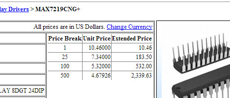
The easiest hint is the price. The non-originals are always cheaper. And if you wonder how much the real ones are in bulk, the quickest indicator is to check the Maxim website and that of a few larger distributors  For example the Maxim “sticker price” for 1000 units is US$4.18 each:

maxpricing

How much at Digikey? Lots of 500 for US$4.67 each:

digikey

And you wouldn’t buy just one from element14 at this price:

aue14pricing

However in fairness to element14 they will price match if you’re buying in volume. So if you can get a “MAX7219″ delivered for US$1.50 – there’s something wrong. Moving on, let’s examine some of those cheap ones in more detail.

Visual differences

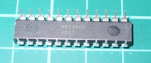
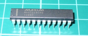
If you’ve never seen a real MAX7219 – here it is, top and bottom:

realtopss

realbottomss

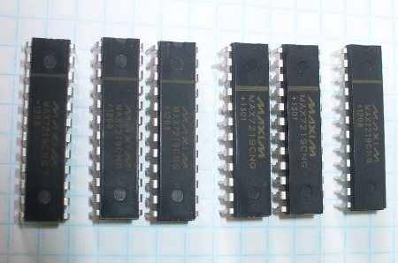
And here’s our rogue’s gallery of test subjects:

testsubjectsss

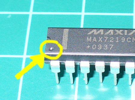
In a few seconds the differences should be blindingly obvious – look at the positioning of the printed bar across the part, the printing of the logo, and the general quality and positioning of the printing. Next, those circles embedded in the top of the body at both ends of the part, and the semi-circle at the top end. And if you turn them over, there’s nothing on the bottom. Furthermore, there isn’t a divot indicating pin 1 on the fakes, as shown on the real part:

divot

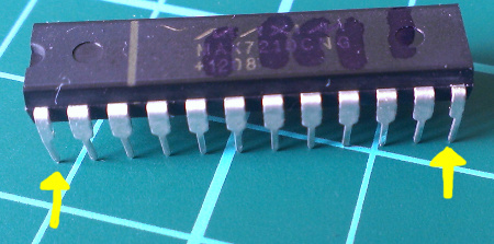
Oh – did you notice the legs on the real one? Look closely again at the image above, then consider the legs on the others below:

fakelegsss

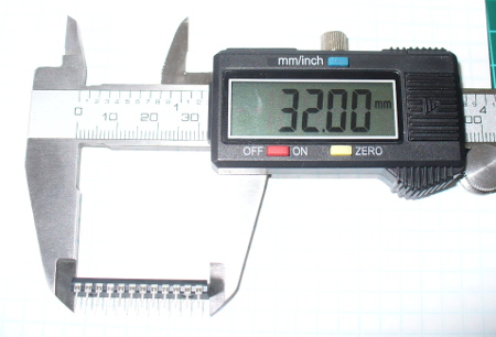
Finally, the non-originals are shorter. The Maxim width can fall between 28.96 and 32.13 mm – with our original test MAX7219 being 32 mm:

realwidthss

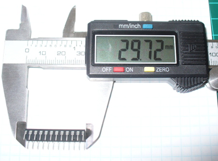
and all the test subjects are narrower, around 29.7 mm:

fakewidthss

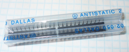
Fascinating. Finally, I found the quality of the metal used for the legs to be worse than the original, they were easier to bend and had trouble going into an IC socket. You can find all the physical dimensions and other notes in the data sheet available from the Maxim website. Finally, this packaging made me laugh – knock-offs in knock-off tubes? (Maxim purchased Dallas Semiconductor a while ago)

faketubingss

Weight difference

Considering that they’re shorter, they must weigh less. In the following video I put the original on the scales, tare it to zero then place each test subject – you can see the difference in weigh. The scales are out a bit however the differences are still obvious:

However over time the manufacturers may go to the effort of making copies that match the weight, size and printing – so future copies may be much better. However you can still fall back to the price to determine a copy.

Do they actually work? 

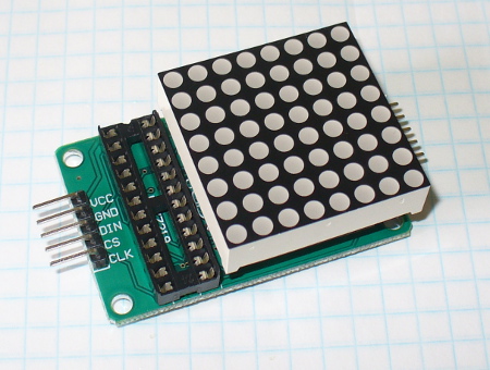
After all that researching and measuring – did they work? One of the subjects came with a small LED matrix breakout board kit:

matrixassembledss

… so I used that with a simple Arduino sketch that turned on each matrix LED one at a time, then went through the PWM levels – then left them all on at maximum brightness.

#include "LedControl.h"
LedControl lc=LedControl(12,11,10,1); // data, clock, load, 1 MAX7219
void setup() 
{
 lc.shutdown(0,false);
 lc.setIntensity(0,15);
 lc.clearDisplay(0);
}
void single() {
 for(int row=0;row<8;row++) {
 for(int col=0;col<8;col++) {
 delay(25);
 lc.setLed(0,row,col,true);
 delay(25);
 for(int i=0;i
void loop() 
{ 
 single();
 for (int n=0; n<5; n++)
 {
 for (int z=0; z<16; z++)
 {
 lc.setIntensity(0,z);
 delay(100);
 }
 for (int z=15; z>-1; --z)
 {
 lc.setIntensity(0,z);
 delay(100);
 }
 }
 lc.setIntensity(0,15);
 do { }  while(1);
}

Here’s the real MAX7219 running through the test:

And test subjects one through to six running it as well:

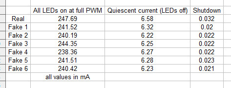
And from a reader request, some current measurements. First the current used by the entire matrix module at full PWM brightness, then with LEDs off, then the MAX7219 in shutdown mode:

current

Well that was disheartening. I was hoping and preparing for some blue smoke, dodgy displays or other faults. However the little buggers all worked, didn’t overheat or play up at all.

Conclusion

Six random samples from ebay – and they all worked. However your experience may vary wildly. Does this tell us that copies are OK to use? From my own personal opinion – you do what you have to do with respect to your own work and that for others. In other words – if you’re making something for someone, whether it be a gift or a commercial product, or something you will rely on – use the real thing. You can’t risk a fault in those situations.  If you’re just experimenting, not in a hurry, or just don’t have the money – try the cheap option. But be prepared for the worst – and know you’re supporting an industry that ethically shouldn’t exist. And at the end – to be sure you’re getting a real one – choose from a Maxim authorised source.

I’m sure everyone will have an opinion on this, so let us know about it in the moderated comments section below.  And if you made it this far – check out my new book “Arduino Workshop” from No Starch Press.

In the meanwhile have fun and keep checking into tronixstuff.com. Why not follow things on twitterGoogle+, subscribe  for email updates or RSS using the links on the right-hand column? And join our friendly Google Group – dedicated to the projects and related items on this website. Sign up – it’s free, helpful to each other –  and we can all learn something.


Introduction

[Here's the Arduino tutorial]

If you’re experimenting with various Arduino or other projects and working with LED matrices or lots of LEDs – you may have come across the Maxim MAX7219 “Serially Interfaced, 8-Digit, LED Display Driver” IC. It’s a great part that can drive an 8 x 8 LED matrix or eight digits of seven-segment LED displays very easily. However over the last few years the price has shot up considerably. Supply and demand doing their thing – and for a while there was also the Austria Microsystems AS1107 drop-in replacement, which could be had for a few dollars less. But no more.

So where does the budget-minded person go from here? Charlieplexing? Lots of shift registers? Or dig a little deeper to find some cheaper units. With a MAX7219 heading north of US$10 in single units, they may turn to ebay or other grey-market suppliers in the Far East. Everyone likes to save money – and who can blame them? However with the proliferation of counterfeiting, “third shift” operations and other shifty practices – is buying those cheaper examples worth it?

A few people have been asking me of late, and there’s only one way to find out … so over the last month I ordered eight random “MAX7219s” from different suppliers on ebay and will compare them to the real thing using somewhat unscientific methods, then see how they work. The funny thing was that after five weeks only six of the eight arrived – so there’s risk number one: if it doesn’t come from a reputable supplier, it might not come at all. Funny stuff. Anyhow, let’s get started by looking at the differences between the real MAX7219 and the others. (Or if you want to learn how to use the MAX7219 with Arduino – click here).

Pricing differences

The easiest hint is the price. The non-originals are always cheaper. And if you wonder how much the real ones are in bulk, the quickest indicator is to check the Maxim website and that of a few larger distributors  For example the Maxim “sticker price” for 1000 units is US$4.18 each:

maxpricing

How much at Digikey? Lots of 500 for US$4.67 each:

digikey

And you wouldn’t buy just one from element14 at this price:

aue14pricing

However in fairness to element14 they will price match if you’re buying in volume. So if you can get a “MAX7219″ delivered for US$1.50 – there’s something wrong. Moving on, let’s examine some of those cheap ones in more detail.

Visual differences

If you’ve never seen a real MAX7219 – here it is, top and bottom:

realtopss

realbottomss

And here’s our rogue’s gallery of test subjects:

testsubjectsss

In a few seconds the differences should be blindingly obvious – look at the positioning of the printed bar across the part, the printing of the logo, and the general quality and positioning of the printing. Next, those circles embedded in the top of the body at both ends of the part, and the semi-circle at the top end. And if you turn them over, there’s nothing on the bottom. Furthermore, there isn’t a divot indicating pin 1 on the fakes, as shown on the real part:

divot

Oh – did you notice the legs on the real one? Look closely again at the image above, then consider the legs on the others below:

fakelegsss

Finally, the non-originals are shorter. The Maxim width can fall between 28.96 and 32.13 mm – with our original test MAX7219 being 32 mm:

realwidthss

and all the test subjects are narrower, around 29.7 mm:

fakewidthss

Fascinating. Finally, I found the quality of the metal used for the legs to be worse than the original, they were easier to bend and had trouble going into an IC socket. You can find all the physical dimensions and other notes in the data sheet available from the Maxim website. Finally, this packaging made me laugh – knock-offs in knock-off tubes? (Maxim purchased Dallas Semiconductor a while ago)

faketubingss

Weight difference

Considering that they’re shorter, they must weigh less. In the following video I put the original on the scales, tare it to zero then place each test subject – you can see the difference in weigh. The scales are out a bit however the differences are still obvious:

However over time the manufacturers may go to the effort of making copies that match the weight, size and printing – so future copies may be much better. However you can still fall back to the price to determine a copy.

Do they actually work? 

After all that researching and measuring – did they work? One of the subjects came with a small LED matrix breakout board kit:

matrixassembledss

… so I used that with a simple Arduino sketch that turned on each matrix LED one at a time, then went through the PWM levels – then left them all on at maximum brightness.

#include "LedControl.h"
LedControl lc=LedControl(12,11,10,1); // data, clock, load, 1 MAX7219
void setup() 
{
 lc.shutdown(0,false);
 lc.setIntensity(0,15);
 lc.clearDisplay(0);
}
void single() {
 for(int row=0;row<8;row++) {
 for(int col=0;col<8;col++) {
 delay(25);
 lc.setLed(0,row,col,true);
 delay(25);
 for(int i=0;i
void loop() 
{ 
 single();
 for (int n=0; n<5; n++)
 {
 for (int z=0; z<16; z++)
 {
 lc.setIntensity(0,z);
 delay(100);
 }
 for (int z=15; z>-1; --z)
 {
 lc.setIntensity(0,z);
 delay(100);
 }
 }
 lc.setIntensity(0,15);
 do { }  while(1);
}

Here’s the real MAX7219 running through the test:

And test subjects one through to six running it as well:

And from a reader request, some current measurements. First the current used by the entire matrix module at full PWM brightness, then with LEDs off, then the MAX7219 in shutdown mode:

current

Well that was disheartening. I was hoping and preparing for some blue smoke, dodgy displays or other faults. However the little buggers all worked, didn’t overheat or play up at all.

Conclusion

Six random samples from ebay – and they all worked. However your experience may vary wildly. Does this tell us that copies are OK to use? From my own personal opinion – you do what you have to do with respect to your own work and that for others. In other words – if you’re making something for someone, whether it be a gift or a commercial product, or something you will rely on – use the real thing. You can’t risk a fault in those situations.  If you’re just experimenting, not in a hurry, or just don’t have the money – try the cheap option. But be prepared for the worst – and know you’re supporting an industry that ethically shouldn’t exist. And at the end – to be sure you’re getting a real one – choose from a Maxim authorised source.

I’m sure everyone will have an opinion on this, so let us know about it in the moderated comments section below.  And if you made it this far – check out my new book “Arduino Workshop” from No Starch Press.

LEDborder

In the meanwhile have fun and keep checking into tronixstuff.com. Why not follow things on twitterGoogle+, subscribe  for email updates or RSS using the links on the right-hand column? And join our friendly Google Group – dedicated to the projects and related items on this website. Sign up – it’s free, helpful to each other –  and we can all learn something.

The post The MAX7219 LED display controller – real or fake? appeared first on tronixstuff.

Over the last few years I’ve been writing a few Arduino tutorials, and during this time many people have mentioned that I should write a book. And now thanks to the team from No Starch Press this recommendation has morphed into my new book – “Arduino Workshop“:

shot11

Although there are seemingly endless Arduino tutorials and articles on the Internet, Arduino Workshop offers a nicely edited and curated path for the beginner to learn from and have fun. It’s a hands-on introduction to Arduino with 65 projects – from simple LED use right through to RFID, Internet connection, working with cellular communications, and much more.

Each project is explained in detail, explaining how the hardware an Arduino code works together. The reader doesn’t need any expensive tools or workspaces, and all the parts used are available from almost any electronics retailer. Furthermore all of the projects can be finished without soldering, so it’s safe for readers of all ages.

The editing team and myself have worked hard to make the book perfect for those without any electronics or Arduino experience at all, and it makes a great gift for someone to get them started. After working through the 65 projects the reader will have gained enough knowledge and confidence to create many things – and to continue researching on their own. Or if you’ve been enjoying the results of my thousands of hours of work here at tronixstuff, you can show your appreciation by ordering a copy for yourself or as a gift :)

You can review the table of contents, index and download a sample chapter from the Arduino Workshop website.

Arduino Workshop is available from No Starch Press in printed or ebook (PDF, Mobi, and ePub) formats. Ebooks are also included with the printed orders so you can get started immediately.

04/07/2013 – (my fellow) Australians – currently the easiest way of getting a print version is from Little Bird Electronics.

In the meanwhile have fun and keep checking into tronixstuff.com. Why not follow things on twitterGoogle+, subscribe  for email updates or RSS using the links on the right-hand column? And join our friendly Google Group – dedicated to the projects and related items on this website. Sign up – it’s free, helpful to each other –  and we can all learn something.


Over the last few years I’ve been writing a few Arduino tutorials, and during this time many people have mentioned that I should write a book. And now thanks to the team from No Starch Press this recommendation has morphed into my new book – “Arduino Workshop“:

shot11

Although there are seemingly endless Arduino tutorials and articles on the Internet, Arduino Workshop offers a nicely edited and curated path for the beginner to learn from and have fun. It’s a hands-on introduction to Arduino with 65 projects – from simple LED use right through to RFID, Internet connection, working with cellular communications, and much more.

Each project is explained in detail, explaining how the hardware an Arduino code works together. The reader doesn’t need any expensive tools or workspaces, and all the parts used are available from almost any electronics retailer. Furthermore all of the projects can be finished without soldering, so it’s safe for readers of all ages.

The editing team and myself have worked hard to make the book perfect for those without any electronics or Arduino experience at all, and it makes a great gift for someone to get them started. After working through the 65 projects the reader will have gained enough knowledge and confidence to create many things – and to continue researching on their own. Or if you’ve been enjoying the results of my thousands of hours of work here at tronixstuff, you can show your appreciation by ordering a copy for yourself or as a gift :)

You can review the table of contents, index and download a sample chapter from the Arduino Workshop website.

Arduino Workshop is available from No Starch Press in printed or ebook (PDF, Mobi, and ePub) formats. Ebooks are also included with the printed orders so you can get started immediately.

LEDborder

In the meanwhile have fun and keep checking into tronixstuff.com. Why not follow things on twitterGoogle+, subscribe  for email updates or RSS using the links on the right-hand column? And join our friendly Google Group – dedicated to the projects and related items on this website. Sign up – it’s free, helpful to each other –  and we can all learn something.

The post Book – “Arduino Workshop – A Hands-On Introduction with 65 Projects” appeared first on tronixstuff.
In this article we review a couple of SMT prototyping boards from Schmartboard.

Introduction

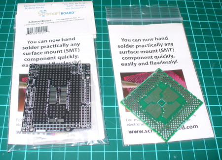
Sooner or later you’ll need to use a surface-mount technology component. Just like taxes and myki* not working, it’s inevitable. When the time comes you usually have a few options – make your own PCB, then bake it in an oven or skillet pan; get the part on a demo board from the manufacturer (expensive); try and hand-solder it yourself using dead-bug wiring or try to mash it into a piece of strip board; or find someone else to do it. Thanks to the people at Schmartboard you now have another option which might cost a few dollars more but guarantees a result. Although they have boards for almost everything imaginable, we’ll look at two of them – one for QFP packages and their Arduino shield that has SOIC and SOP23-6 areas.

boards

QFP 32-80 pin board

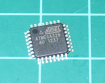
In our first example we’ll see how easy it is to prototype with QFP package ICs. An example of this is the Atmel ATmega328 microcontroller found on various Arduino-compatible products, for example:

atmega

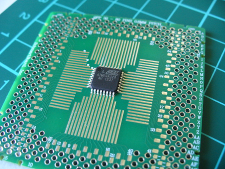
Although our example has 32 pins, the board can handle up to 80-pin devices. You simply place the IC on the Schmartboard, which holds the IC in nicely due to the grooved tracks for the pins:

atmegabefore

The tracks are what makes the Schmartboard EZ series so great – they help hold the part in, and contain the required amount of solder. I believe this design is unique to Schmartboard and when you look in their catalogue, select the “EZ” series for this technology. Moving forward, you just need some water-soluble flux:

fluxpen

then tack down the part, apply flux to the side you’re going to solder – then slowly push the tip of your soldering iron (set to around 750 degrees F) down the groove to the pin. For example:

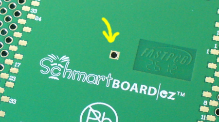
Then repeat for the three other sides. That’s it. If your part has an exposed pad on the bottom, there’s a hole in the centre of the Schmartboad that you can solder into as well:

qfpheat

After soldering I really couldn’t believe it worked, so probed out the pins to the breakout pads on the Schmartboard to test for shorts or breaks – however it tested perfectly. The only caveat is that your soldering iron tip needs to be the same or smaller pitch than the the part you’re using, otherwise you could cause a solder bridge. And use flux!  You need the flux. After soldering you can easily connect the board to the rest of your project or build around it.

Schmartboard Arduino shield

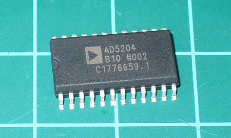
There’s also a range of Arduino shields with various SMT breakout areas, and we have the version with 1.27mm pitch SOIC and a SOT23-6 footprint. SOIC? For example:

soicic

This is the AD5204 four-channel digital potentiometer we used in the SPI tutorial. It sits nicely in the shield and can be easily soldered onto the board. Don’t forget the flux! Although the SMT areas have the EZ-technology, I still added a little solder of my own – with satisfactory results:

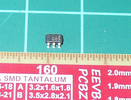
The SOT23-6 also fits well, with plenty of space for soldering it in. SOT23? Example – the ADS1110 16-bit ADC which will be the subject of a future tutorial:

ads1110

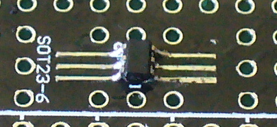
Working with these tiny components is also feasible but requires a finer iron tip and a steady hand.

sot236

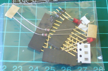
Once the SMT component(s) have been fitted, you can easily trace out the matching through-hole pads for further connections. The shield matches the Arduino R3 standards and includes stacking header sockets, two LEDs for general use, space and parts for an RC reset circuit, and pads to add pull-up resistors for the I2C bus:

otherparts

Finally there’s also three 0805-sized parts and footprints for some practice or use. It’s a very well though-out shield and should prove useful. You can also order a bare PCB if you already have stacking headers to save money.

Conclusion

If you’re in a hurry to prototype with SMT parts, instead of mucking about – get a Schmartboard. They’re easy to use and work well.  Full-sized images available on flickr.

In the meanwhile have fun and keep checking into tronixstuff.com. Why not follow things on twitterGoogle+, subscribe  for email updates or RSS using the links on the right-hand column? And join our friendly Google Group – dedicated to the projects and related items on this website. Sign up – it’s free, helpful to each other –  and we can all learn something.

The boards used in this article were a promotional consideration supplied by Schmartboard.

*myki

The post Review – Schmartboard SMT Boards appeared first on tronixstuff.

Introduction

In the same manner as their MSP430 development board, Texas Instruments also have another LaunchPad board with their powerful Stellaris LM4F120H5QR microcontroller. It’s an incredibly powerful and well-featured MCU – which offers an 80 MHz, 32-bit ARM Cortex-M4 CPU with floating point, 256 Kbytes of 100,000 write-erase cycle FLASH and many peripherals such as 1MSPS ADCs, eight UARTs, four SPIs, four I2Cs, USB & up to 27 timers, some configurable up to 64-bits.

That’s a bucket of power, memory and I/O for not much money – you can get the LaunchPad board for around $15. This LaunchPad has the in-circuit debugger, two user buttons, an RGB LED and connectors for I/O and shield-like booster packs:

and the other side:

However the good news as far as we’re concerned is that you can now use it with the Energia Arduino-compatible IDE that we examined previously. Before rushing out to order your own Stellaris board, install Energia and examine the available functions and libraries to make sure you can run what you need. And if so, you’re set for some cheap Arduino power.

Installation

Installation is simple, just get your download from here. If you’re running Windows 7 – get the USB drivers from here. When you plug your LaunchPad into the USB for the first time, wait until after Windows attempts to install the drivers, then install drivers manually after download via Device manager … three times (JTAG, virtual serial port and DFU device). Use the debug USB socket (and set the switch to debug) when installing and uploading code. If you get the following warning from Windows, just click “Install this driver software anyway”:

Once the drivers are installed, plug in your LaunchPad, wait a moment – then run Energia. You can then select your board type and serial port just like the Arduino IDE. Then go ahead and upload the “blink” example…

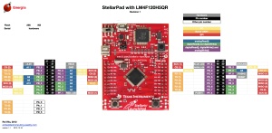
Awesome – check out all that free memory space. In the same manner as the MSP430, there are some hardware<>sketch differences you need to be aware of. For example, how to refer to the I/O pins in Energia? A map has been provided for front:

… and back:

As you can imagine, the Stellaris MCUs are different to an AVR, so a lot of hardware-specific code doesn’t port over from the world of Arduino. One of the first things to remember is that the Stellaris is a 3.3V device. Code may or may not be interchangeable, so a little research will be needed to match up the I/O pins and rewrite the sketch accordingly. For example, instead of digital pins numbers, you use PX_Y - see the map above. So let’s say you want to run through the RGB LED… consider the following sketch:

int wait = 500;
void setup() 
{ 
 // initialize the digital pin as an output.
 pinMode(PF_1, OUTPUT); // red 
 pinMode(PF_3, OUTPUT); // green
 pinMode(PF_2, OUTPUT); // blue
}
void loop() 
{
 digitalWrite(PF_1, HIGH); 
 delay(wait); 
 digitalWrite(PF_1, LOW); 
 digitalWrite(PF_3, HIGH); 
 delay(wait); 
 digitalWrite(PF_3, LOW); 
 digitalWrite(PF_2, HIGH); 
 delay(wait); 
 digitalWrite(PF_2, LOW); 
}

Which simply blinks the red, green and blue LED elements in series. Using digital inputs is in the same vein, and again the buttons are wired so when pressed they go LOW. An example of this in the following sketch:

void setup() 
{ 
 // initialize the digital pins
 pinMode(PF_1, OUTPUT); // red 
 pinMode(PF_3, OUTPUT); // green
 pinMode(PF_2, OUTPUT); // blue

 pinMode(PF_4, INPUT_PULLUP); // left - note _PULLUP
 pinMode(PF_0, INPUT_PULLUP); // right - note _PULLUP 
}
void blinkfast() 
{
 for (int i=0; i<10; i++)
 {
 digitalWrite(PF_1, HIGH); 
 delay(250); 
 digitalWrite(PF_1, LOW); 
 digitalWrite(PF_3, HIGH); 
 delay(250); 
 digitalWrite(PF_3, LOW); 
 digitalWrite(PF_2, HIGH); 
 delay(250); 
 digitalWrite(PF_2, LOW); 
 }
}
void blinkslow() 
{
 for (int i=0; i<5; i++)
 {
 digitalWrite(PF_1, HIGH); 
 delay(1000); 
 digitalWrite(PF_1, LOW); 
 digitalWrite(PF_3, HIGH); 
 delay(1000); 
 digitalWrite(PF_3, LOW); 
 digitalWrite(PF_2, HIGH); 
 delay(1000); 
 digitalWrite(PF_2, LOW); 
 }
}
void loop()
{
 if (digitalRead(PF_4)==LOW) { blinkslow(); }
 if (digitalRead(PF_0)==LOW) { blinkfast(); }
}

And for the non-believers:

Where to from here? 

Sometimes you can be platform agnostic, and just pick something that does what you want with the minimum of time and budget. Or to put it another way, if you need a fast CPU and plenty of space but couldn’t be bothered don’t have time to work with Keil, Code Composer Studio, IAR etc – the Energia/Stellaris combination could solve your problem. There’s a growing Energia/Stellaris forum, and libraries can be found here. At the time of writing we found an I2C library as well.

However to take full advantage of the board, consider going back to the TI tools and move forward with them. You can go further with the tutorials and CCS etc from Texas Instruments own pages.

In the meanwhile have fun and keep checking into tronixstuff.com. Why not follow things on twitterGoogle+, subscribe  for email updates or RSS using the links on the right-hand column? And join our friendly Google Group – dedicated to the projects and related items on this website. Sign up – it’s free, helpful to each other –  and we can all learn something.


Introduction

In the same manner as their MSP430 development board, Texas Instruments also have another LaunchPad board with their powerful Stellaris LM4F120H5QR microcontroller. It’s an incredibly powerful and well-featured MCU – which offers an 80 MHz, 32-bit ARM Cortex-M4 CPU with floating point, 256 Kbytes of 100,000 write-erase cycle FLASH and many peripherals such as 1MSPS ADCs, eight UARTs, four SPIs, four I2Cs, USB & up to 27 timers, some configurable up to 64-bits.

That’s a bucket of power, memory and I/O for not much money – you can get the LaunchPad board for around $15. This LaunchPad has the in-circuit debugger, two user buttons, an RGB LED and connectors for I/O and shield-like booster packs:

and the other side:

However the good news as far as we’re concerned is that you can now use it with the Energia Arduino-compatible IDE that we examined previously. Before rushing out to order your own Stellaris board, install Energia and examine the available functions and libraries to make sure you can run what you need. And if so, you’re set for some cheap Arduino power.

Installation

Installation is simple, just get your download from here. If you’re running Windows 7 – get the USB drivers from here. When you plug your LaunchPad into the USB for the first time, wait until after Windows attempts to install the drivers, then install drivers manually after download via Device manager … three times (JTAG, virtual serial port and DFU device). Use the debug USB socket (and set the switch to debug) when installing and uploading code. If you get the following warning from Windows, just click “Install this driver software anyway”:

Once the drivers are installed, plug in your LaunchPad, wait a moment – then run Energia. You can then select your board type and serial port just like the Arduino IDE. Then go ahead and upload the “blink” example…

stellarisblink

Awesome – check out all that free memory space. In the same manner as the MSP430, there are some hardware<>sketch differences you need to be aware of. For example, how to refer to the I/O pins in Energia? A map has been provided for front:

stellarpad-e28094-pins-maps1

… and back:

stellarpad-back-e28094-pins-maps1

As you can imagine, the Stellaris MCUs are different to an AVR, so a lot of hardware-specific code doesn’t port over from the world of Arduino. One of the first things to remember is that the Stellaris is a 3.3V device. Code may or may not be interchangeable, so a little research will be needed to match up the I/O pins and rewrite the sketch accordingly. For example, instead of digital pins numbers, you use PX_Y - see the map above. So let’s say you want to run through the RGB LED… consider the following sketch:

int wait = 500;
void setup() 
{ 
 // initialize the digital pin as an output.
 pinMode(PF_1, OUTPUT); // red 
 pinMode(PF_3, OUTPUT); // green
 pinMode(PF_2, OUTPUT); // blue
}
void loop() 
{
 digitalWrite(PF_1, HIGH); 
 delay(wait); 
 digitalWrite(PF_1, LOW); 
 digitalWrite(PF_3, HIGH); 
 delay(wait); 
 digitalWrite(PF_3, LOW); 
 digitalWrite(PF_2, HIGH); 
 delay(wait); 
 digitalWrite(PF_2, LOW); 
}

Which simply blinks the red, green and blue LED elements in series. Using digital inputs is in the same vein, and again the buttons are wired so when pressed they go LOW. An example of this in the following sketch:

void setup() 
{ 
 // initialize the digital pins
 pinMode(PF_1, OUTPUT); // red 
 pinMode(PF_3, OUTPUT); // green
 pinMode(PF_2, OUTPUT); // blue

 pinMode(PF_4, INPUT_PULLUP); // left - note _PULLUP
 pinMode(PF_0, INPUT_PULLUP); // right - note _PULLUP 
}
void blinkfast() 
{
 for (int i=0; i<10; i++)
 {
 digitalWrite(PF_1, HIGH); 
 delay(250); 
 digitalWrite(PF_1, LOW); 
 digitalWrite(PF_3, HIGH); 
 delay(250); 
 digitalWrite(PF_3, LOW); 
 digitalWrite(PF_2, HIGH); 
 delay(250); 
 digitalWrite(PF_2, LOW); 
 }
}
void blinkslow() 
{
 for (int i=0; i<5; i++)
 {
 digitalWrite(PF_1, HIGH); 
 delay(1000); 
 digitalWrite(PF_1, LOW); 
 digitalWrite(PF_3, HIGH); 
 delay(1000); 
 digitalWrite(PF_3, LOW); 
 digitalWrite(PF_2, HIGH); 
 delay(1000); 
 digitalWrite(PF_2, LOW); 
 }
}
void loop()
{
 if (digitalRead(PF_4)==LOW) { blinkslow(); }
 if (digitalRead(PF_0)==LOW) { blinkfast(); }
}

And for the non-believers:

Where to from here? 

Sometimes you can be platform agnostic, and just pick something that does what you want with the minimum of time and budget. Or to put it another way, if you need a fast CPU and plenty of space but couldn’t be bothered don’t have time to work with Keil, Code Composer Studio, IAR etc – the Energia/Stellaris combination could solve your problem. There’s a growing Energia/Stellaris forum, and libraries can be found here. At the time of writing we found an I2C library as well.

However to take full advantage of the board, consider going back to the TI tools and move forward with them. You can go further with the tutorials and CCS etc from Texas Instruments own pages.

In the meanwhile have fun and keep checking into tronixstuff.com. Why not follow things on twitterGoogle+, subscribe  for email updates or RSS using the links on the right-hand column? And join our friendly Google Group – dedicated to the projects and related items on this website. Sign up – it’s free, helpful to each other –  and we can all learn something.

The post Exploring the TI Stellaris platform with Energia Arduino-compatible IDE appeared first on tronixstuff.
Introduction

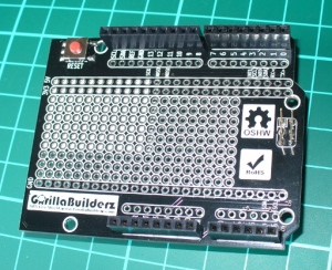
Some of you may be using an Arduino Leonardo board, taking advantage of the newer ATmega32U4 microcontroller for various reasons. And rightly so – there’s the extra analogue I/O, virtual USB and the microUSB socket so you can use your phone charger cable. However with the new microcontroller comes a few changes to the board pinouts – I2C and SPI have moved. So if you have a nice Ethernet shield or something using I2C – you’re basically out of luck… until now. The problem has been solved nicely by the team at GorillaBuilderz have created their LeoShield:
Use

You simply place it on the Leonardo, and then the older legacy shield on top. The LeoShield redirects the I2C pins back to A4 and A5, and also sends the SPI lines back to D11~D13. For example, our Ethernet shield:

The ICSP pins are also extended from the Leonardo to the LeoShield, for example:

however when inserting the LeoShield into your Leonardo, take care lining up all the pins before pushing the shield down. There is also the large prototyping area which has 5V , 3.3V and GND rails across the full width for convenience. The sticker on the rear of the shield is to insulate against any large items that may come in contact from the host board, however you can peel it off to realise the complete prototyping space.

Conclusion

It’s simple and it works – so if you need to use an older Arduino shield with a Leonardo the choice is simple – get yourself a Leoshield.

Disclaimer - The Leoshield was a review product received from GorillaBuilderz.

Thanks for reading tronixstuff.com. I’ve got some new tutorials coming up very soon, and a lot of existing posts are curently being updated – so follow things on twitterGoogle+, subscribe  for email updates or RSS using the links on the right-hand column. And join our friendly Google Group – dedicated to the projects and related items on this website. Sign up – it’s free, helpful to each other –  and we can all learn


  • Newsletter

    Sign up for the PlanetArduino Newsletter, which delivers the most popular articles via e-mail to your inbox every week. Just fill in the information below and submit.

  • Like Us on Facebook