Today we are going to make a real time clock Arduino shield. If you have been following my tutorials, in weeks 7, 8 and onwards we have been making use of the Maxim DS1307 real time clock chip. Although it is a very interesting part to use, implementing it has not been so easy, therefore the reason for this shield. So let’s go!
First of all, we need create our circuit diagram. Thankfully the Maxim DS1307 data sheet [pdf] has this basics laid out on page one. From examining a DS1307 board used in the past, the pull-up resistors used were 10k ohm metal films, so I’m sticking with that value. The crystal to use is 32.768 kHz, and thankfully Maxim have written about that as well in their application notes [pdf], even specifying which model to use. Phew!
So here is the circuit diagram we will follow (click on it to enlarge):
Which gives us the following shopping list:
One arduino protoshield pack. I like the yellow ones from Freetronics, however others may prefer this one
X1 – 32.768 kHz crystal – Citizen America part CFS206. You should probably order a few of these, I broke my first one very quickly…
The first thing to do is create the circuit on a solderless breadboard. It is much easier to troubleshoot possible issues before soldering the circuit together. Here is the messy test:
Messy or not, it worked. Instead of writing another sketch, the example 7.3 from arduino tutorial seven was used. Here is a copy: example 7.3.pdf.
The next step is to consider the component placement and wiring for the protoshield. Try not to rush this step, and triple-check your layout against the schematic. As my protoshield has a green and red LED as well, I have wired the square-wave output to the green LED. You can never have too many blinking lights…
At this point I celebrated the union of tea and a biscuit. After returning to the desk, I checked the layout once more, and planned the solder bridges. All set – it was time to solder up. If you have the battery in the holder for some reason, you should remove it now, as they do not like getting warm. Furthermore, that crystal is very fragile, so please solder it in quickly.
And here we are – all soldering done except for the header sockets. At this point I used the continuity function of the multimeter to check the solder joints and make sure nothing was wrong with the circuit.
Final checks passed, so on with the headers. To make this easier, I stick some header pins in the sockets, then place the whole lot in a solderless breadboard to keep it straight. Well, it works for me:
Just a side note – always make sure you have enough consumables, the right tools, etc., before you start a project. This is how much solder I had left afterwards…
Moving on … in with the battery and the DS1307 – we’re done!
It is now time for the moment of truth – to insert the USB cable and re-run the sketch… and it worked! The blinking LED was too bright for me, so I de-soldered the wire. If you are making a shield, congratulations to you if yours worked as well. If it did not, don’t be afraid to hit me up via email or our Google Group with your questions. Note that if you are using this shield, you cannot use analog pins 4 and 5 – they are being used as the I2C bus. Time to clear up the desk and wash my hands.
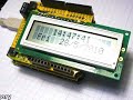
Now to put this shield to work. Last week we made an LCD module shield – so let’s pile up the shields and make a digital clock. We can re-use the sketch from arduino tutorial example 7.4, with the liquidcrystal() corrected to use the LCD shield pins. Here is the modified sketch: ds1307shielddemo.pdf.
And my post wouldn’t be complete without a video, so here are our new shields in action!
So there we have it. Another useful shield, and proof that the Arduino system makes learning easy and fun. High resolution photos are available on flickr. If you have any questions or comments, please leave them below, or consider joining our Google Group!
As always, thank you for reading and I look forward to your comments and so on. Please subscribe using one of the methods at the top-right of this web page to receive updates on new posts!
Hello once again to our regular Arduino tutorial instalment. This week are up to all sorts of things, including: distance sensing, using prototyping shields, even more shiftiness with shift registers and 4-digit 7-segment displays, and some exercises to refresh and expand your knowledge. Wow – let’s get cracking…
Do you know how to keep your distance? Some people do, some do not. The same goes for mechatronical things (i.e. robots, those little autonomous vacuum cleaners, etc). So to solve that problem you can integrate a distance sensor into your design. Hopefully by following this section you will gain an understanding of such sensors, and be able to make use of them later on in your own projects. Anyhow, today we are looking at the Sharp GP2Y0A21YK0F infra-red distance sensor. What a mouthful… The funny thing is that it looks like a robot head:
That white JST connector is for three leads, +5V, GND, and analogue out. When purchasing it you should also get a matching lead to save time and mucking about.
How it works is quite simple (I must stop writing that, some things are not as simple as they seem…) – the sensor contains an infra-red transmitter and a receiver. It returns a voltage that is relative to the distance between itself and the object in front of it. This output voltage is inversely proportional to the distance; which is explained better with this graph from the data sheet:
However it is always fun to test these things out yourself. So I placed a sensor up over my desk, measured out 80cm, and attached the multimeter to the analogue output of the sensor.
A crude setup but effective. I held a white piece of cardboard in front of the sensor, starting from more than one metre away, then moved closer to the minimum, then back out again. As shown in this video clip:
Although watching that multimeter may not have been too interesting, hopefully the next task will be!
Exercise 6.1
Using the values from the graph from the Sharp data sheet (above), make yourself a distance-measuring device. Use an LCD module to display the measurements. Metric and imperial! This shouldn’t be too hard at all, you’re just using one analogue input from the sensor, some basic maths, and displaying some data on an LCD. Furthermore, to make it truly portable, you could wire up a 9v PP3 battery to a DC plug and use it for power. A hint – before calculating distances, run a sketch to just return the analogRead() value from the sensor. Then you can make your own judgement on voltage-distance calculations. To save time I used the Electronic Bricks to rapidly construct this prototype.
You will need:
Your standard Arduino setup (computer, cable, Duemilanove)
Finally, my sketch for the solution: Exercise 6.1.pdf. You may have to adjust the values in the decision tree for more accuracy. After spending some time with this sensor, I wouldn’t rely on it for exact distance calculations, however it would be very useful for general item detection, air switches and so on. In the next week or two we will examine another type of distance sensor.
What else could this be used for? Robotics sensors, burglar alarms, switching things on and off. Hopefully you have gained some knowledge about this sensor and have some ideas for implementation.
Coffee time.
Now that we have spent a few weeks constructing our prototypes on breadboards and electronic bricks, it is now time to look at how we can do this in a more compact, and/or permanent method. As you already know, the Arduino system allows for “shields”, PCBs that plug on top of your Arduino board to add some sort of extra functionality. One of these was the Electronic Brick chassis, another popular shield is the ethernet shield.
Well that’s all very nice, but can we do this ourselves? Of course. You need a prototyping shield. There are two main types of protoshield, one that contains a small solderless breadboard that can be used on the shield:
or a shield that is plainly a PCB, ready to solder a circuit onto it. This one below is great, it includes two extra LEDs and a button. Furthermore, the yellow PCB makes things easier to see:
As you can imagine, one is more permanent than the other. In this chapter you can follow me create my own circuit on the plain PCB protoshield.
Recently I purchased a couple of blank protoshields (the yellow one above) in order to make a shield with two 7-segment LED displays and 74HC595 shift registers – as it takes a long time to wire these up on a breadboard. So after composing a diagram of which pins are connected to which pins, it was time to place the components and start soldering.
The board basically a matrix of through-plated holes, so you can solder into them from both sides. Which makes linking them together very simple:
However you really need to be careful planning your board, top and bottom, to avoid things getting messy:
Another trap to look out for is trying to squeeze too much in at once. This can cause you to do some very creative soldering:
The plan was to have two wires in the one hole, a lead and a resistor tail. Very difficult for me to do neatly. However at the end it all came together… somehow!
With this example, some wires have been soldered on the read. In fact, most of them were on the rear. Anyhow, the last thing to do is solder in the header pins in order for our new protoshield to stack on top of our Arduino. You can either solder on full header sockets, just like the Arduino, or pins if you don’t need to stack another shield on top of yours. In this case you would not cover up the displays, so only pins will be used. The best way to solder the pins is to place them into your Arduino, put your shield on top, then solder. Example:
And once it came time to set my shield down on the pins, a very amusing (to me) thing happened – it would not sit straight! All those wires underneath the PCB interfered with the microcontroller on the Arduino itself:
So there is a useful tip for you: always plan your protoshields in all three dimensions! Otherwise things may not go as planned, and you don’t want a leaning tower of shields. But finally, it did work with some careful wire repositioning:
So there you have it, a quick demonstration of what to do and not do when using a blank prototyping shield. In the near future we shall make more use of these.
Moving on…
In previous instalments we have worked with 7-segment LED displays, using up to three at once, being controlled by 74HC595 shift registers. As you may have realised by now that involved a lot of wiring, resistors, time and effort. But what if you need four or more digits? Use an LCD… Maybe. Sometimes you need to use LED displays for aesthetic reasons, price, clarity, or just because you love that LED look. Thankfully you can find four digit displays, instead of having to use 2 x 2 or 4 x 1 digit displays. Let’s have a look at one now:
For the newcomer there would be a surprising lack of pins on this display module. That is a good thing, and a slightly tricky thing – but we can overcome the obstacles and use it very easily. How? Again, with two 74HC595 shift registers and some brainpower. Firstly, let’s have a look at the pins – from left to right they are: E, D, C, G, F, B, A, C1, C2, C3, C4, decimal point, unused, unused. This display is common cathode, so to display (for example) the number 1 on digit 3, you would apply ~+2 volts to pins 6 and 7, and attach ground to pin 10. Very much the same as using a single-digit display, except you need to choose the cathode that corresponds with the digit you wish to use. In this tutorial we are using a Common Cathode unit. Out of curiosity’s sake, here is the data sheet for the module used in this chapter: data sheet.pdf.
Secondly, how are we going to control the cathodes with out Arduino? Current comes out of a cathode, so it would not accept a signal from our digital out pins. What we need to do is have a simple switch on each cathode between the display pin and ground, so we can control which digit we want to use. How can we do this with our Arduino? Easy… we can use a simple NPN transistor as a switch. Remember we did this with a relay in chapter three!
But using 4 digital out pins for cathode control is a waste of pins, we can use our trusty shift register again to control the cathodes. So that means we need two shift registers in total, the first to control the digit (0~9), and the second to switch on the cathode of the position we wish to display our digit in. Time to do it!
The first (left-hand) shift register from the Arduino controls the segments on the display, via 560 ohm resistors. Just like last time. The second (right-hand) shift register controls the cathodes. Pins Q0~Q3 connect to the base of a BC548 transistor via a 1k ohm resistor. The collector of the transistor is connected to the cathode on the display, and the emitter to ground. For example:
Note that the schematic above is a guide only. But here it is in real life, below:
After a few projects, wiring up displays and shift registers should be a lot quicker for you now. Here is the matching sketch I came up with for the demonstration video below: Example 6.1.pdf
You’d have to admit, even in the year 2010, LED displays still look mesmerising. Or maybe that’s just me! Here is the data sheet display.pdf for the LED display I used. You can use other ones,as long as they are common cathode; just match the LED element pins with your first shift register, and the cathode pins with the second shift register.
But on to making something useful…
Exercise 6.2
Using the hardware from example 6.1 above, create a device that displays the value of an analogue sensor. For example, if we connect a 10k variable resistor to an analogue input, the Arduino will return a reading of between 0 and 1023. From a hardware perspective, all you need to do is add an analogue sensor (e.g. LDR, 10k variable resistor, the infra-red sensor from earlier on, etc.). The software will be a little tricky, but if you completed exercise 5.1, or 5.2 you shouldn’t have a problem at all. As you will be displaying one digit at a time, but very quickly, try to minimise the number of times you clear the display – in doing so you will keep the brightness at a maximum.
You will need:
Your standard Arduino setup (computer, cable, Duemilanove)
One 4-digit, 7-segment LED display, common cathode
That wasn’t too hard was it? Now that you can use such a display, it will become easier to display output from your various projects.
Another week over! And again, I’m already excited about writing the next instalment… Congratulations to all those who took part and built something useful! Please subscribe (see the top right of this page) to receive notifications of new articles. High resolution photos are available from flickr.
If you have any questions at all please leave a comment (below). If you would like to showcase your work from this article, email a picture or a link to john at tronixstuff dot com.
You might even win a prize. Don’t forget to check out the range of gear at Little Bird Electronics!
Planet Arduino is, or at the moment is wishing to become, an aggregation of public weblogs from around the world written by people who develop, play, think on Arduino platform and his son. The opinions expressed in those weblogs and hence this aggregation are those of the original authors. Entries on this page are owned by their authors. We do not edit, endorse or vouch for the contents of individual posts. For more information about Arduino please visit www.arduino.cc
You are currently browsing the archives for the protoshields category.