Posts | Comments

Planet Arduino

Archive for the ‘nRF24L01+’ Category

Hey geeks welcome back to the techatronic. This time we have made this great project which is NRF Remote control for Rc car. This remote control can control any of the cars. there is one more device which need to be install in the car or the other device which will control by the remote. the remote control have one transceiver and one controller which manage the remote.

NRF Remote Control for RC Car

Introduction

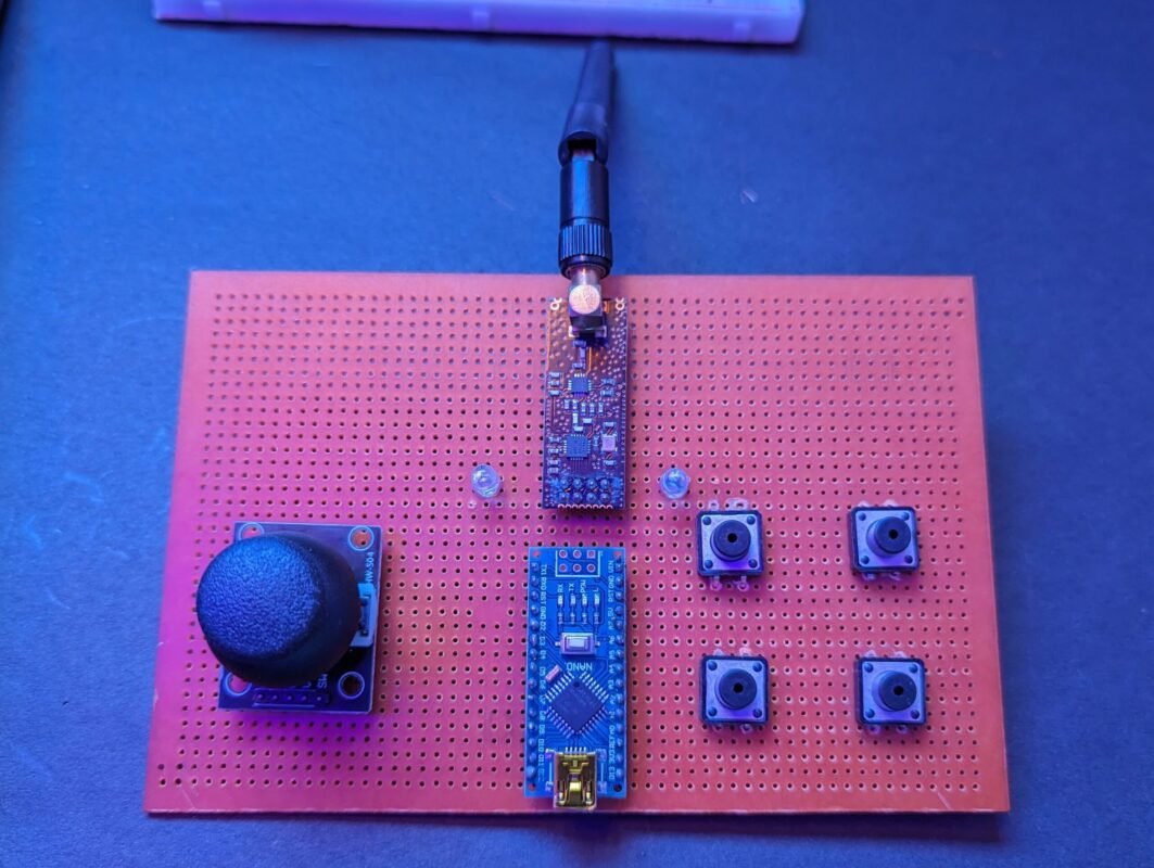
This RC remote control is made by the NRF24L01 module which is responsible for wireless communication which you can see in the images. This remote will be paired with the receiver device automatically. and when you press any key or joystick module it will send the information. Previously we made a gesture control robot where we have use the Bluetooth hc-05 master slave communication system. thee master module send the information through the Bluetooth module. the same process uses in this project. but using the NRF module.

The range of the communication of the module is great nearly 100 meters. that is the only reason to use this nrf module in this NRF 24L01 Remote Control for RC Car. All the information will bee provided here how to interface nrf with Arduino, coding and circuit. to make this great project by yourself you need to follow the given instructions.

Here is the list of part’s we are using.

Components Required:-

  • NRF24L01 with antenna
  • Arduino nano
  • Joystick module
  • Zero PCB
  • push button
  • wires
nrf module for rc car

NRF24L01 module is a long-range wireless communication module.This nrf module can use 125 different channels which can help to connect the 125 module connect to each other. and from this 125 channels the each channel can have their own 6 unit to communicate.

Also, the power consubtiom of this module is very low. the nrf24l01 module work only on the 10 mA during the transmission. which is very less even power consumption of led is higher than that.

This module sometimes burn when people make the connection due to the required low voltage. it need maximum 3.3v to operate. if you give extra then it will burn. and the main things is there is no indicator led or nothing to see is it working or not. We are using this module in our NRF remote control system for better communication and low power consumption.

The module have spi pins to communicate with the controllers. MOSI, MISO, SCK , CE, CSN. connect this spi pins to the same spi pins of the arduino or the controller which you are using.

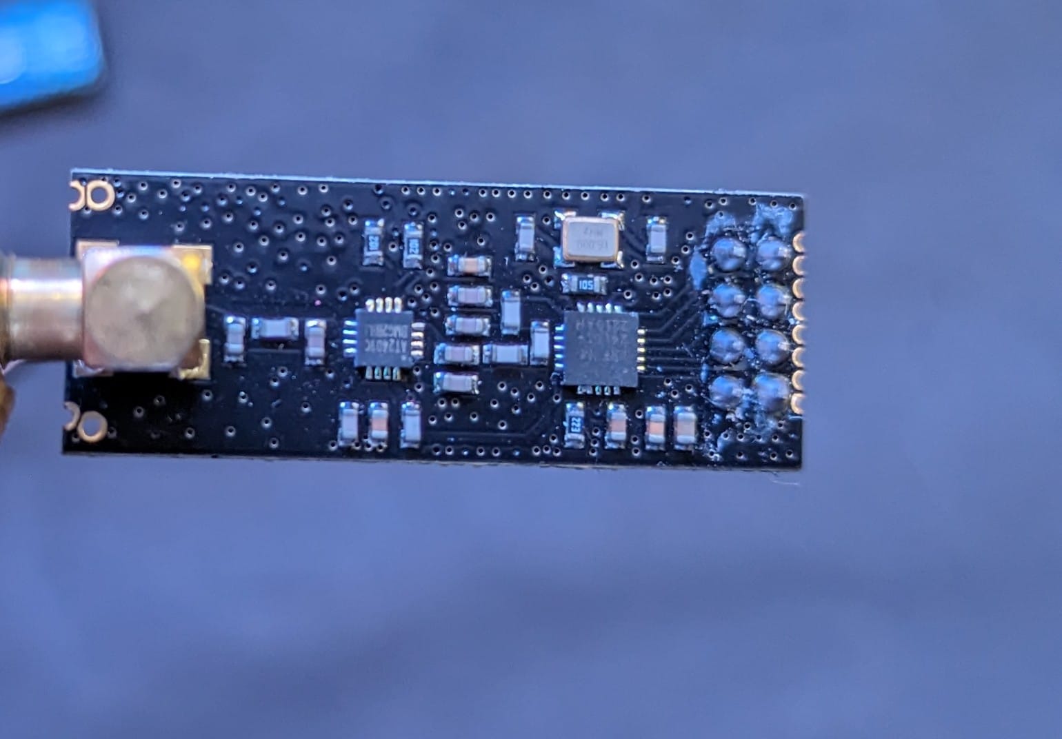
The nrf module available in two different types one is normal NRF24LO1 module and other one with the Long range antenna which enable the communication through the 500 meter. this variation shown here, in addition to the duck antenna, it has a RFX2401C chip which includes PA (Power Amplifier) and LNA (Low-Noise Amplifier). 

We need to connect this module to. the arduino nano which transmit the data to the transmitter to receiver.

Joystick module we have interfaced before with the arduino and here is the link you can get all thee information on it here.

Now we need the Circuit diagram. to complete our project.

NRF Remote Circuit Diagram Transmitter

NRF Remote Control transmitter

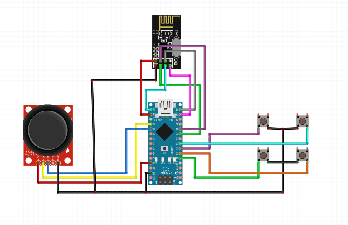
Here you can see the connection clearly in this circuit diagram. joystick verticle and horizontal pin should be connect to the A0 and A1 pins and puch button should connect to the digital input pins. NRF24L01 module connect as required SPI communication.

Connection Table

Arduino nano Joystick moduleNRF 24L01Push Button
pin 2PUSH BUTTON1 T1
pin3 PUSH BUTTON2 T1
pin4PUSH BUTTON3 T1
pin5PUSH BUTTON4 T1
pin7 CE
pin8CSE
pin11MOSI
pin12MISO
pin13SCK
A0V1
A1H1
VCCVCC
GNDGNDGNDPB1 T2, PB2 T2, PB3 T3, PB4 T4
3V3VCC

NRF Remote control Circuit Diagram Receeiver

circuit diagram receiver nrf

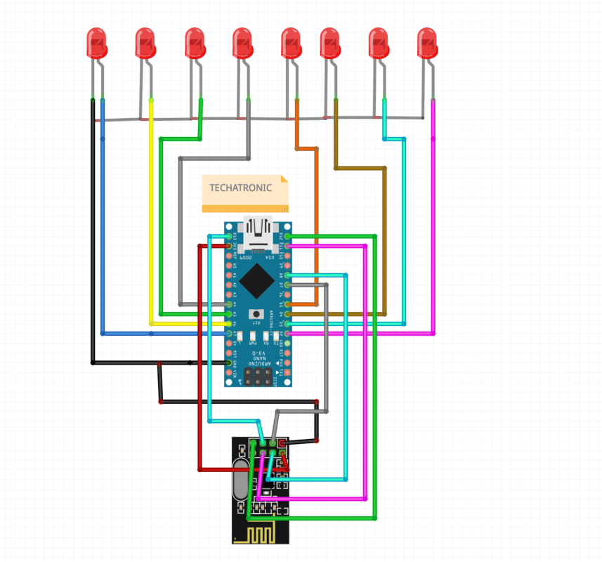
Here the same connection for nrf and arduino and LEDs connect directly to the Arduino nano.

Connection Table

Arduino nano LEDsNRF24L01
A7L1 ANODE
A6L2 ANODE
A5L3 ANODE
A4L4 ANODE
13SCK
12MISO
11MOSI
8CSE
7CE
5L5 ANODE
4L6 ANODE
3L7 ANODE
2L8 ANODE
VCC
GNDALL CATHODEGND
3V3VCC
Now, we need the code.

NRF Remote Control for RC Car code for transmitter

//Library: TMRh20/RF24, https://github.com/tmrh20/RF24/


#include <SPI.h>
#include <nRF24L01.h>
#include <RF24.h>

RF24 radio(7, 8); // CE, CSN

const byte address[6] = "00001";

void setup() {
  Serial.begin(9600);
  radio.begin();
  radio.openWritingPipe(address);
  radio.setPALevel(RF24_PA_MIN);
  radio.stopListening();
  pinMode(2, INPUT_PULLUP);
   pinMode(3, INPUT_PULLUP);
    pinMode(4, INPUT_PULLUP);
     pinMode(5, INPUT_PULLUP);
     pinMode(A0, INPUT_PULLUP);
     pinMode(A1, INPUT_PULLUP);
}

void loop() {

  int m = digitalRead(2);
  int n = digitalRead(3);
  int  o= digitalRead(4);
  int p = digitalRead(5);
  int q = analogRead(A0);
  int r = analogRead(A1);
  Serial.print(m);
  Serial.print("    ");
  Serial.print(n);
  Serial.print("    ");
  Serial.print(o);
  Serial.print("    ");
  Serial.print(p);
  Serial.print("    ");
  Serial.print(q);
  Serial.print("    ");
  Serial.println(r);
 
  
  if(m==0)

  {
    
    const char text[] = "A";
  radio.write(&text, sizeof(text));
  delay(100);
    
    }

   else if(n==0)

  {
    
    const char text[] = "B";
  radio.write(&text, sizeof(text));
  delay(100);
    
    }

    else if(o==0)

  {
    
    const char text[] = "C";
  radio.write(&text, sizeof(text));
  delay(100);
    
    }

    else if(p==0)

  {
    
    const char text[] = "D";
  radio.write(&text, sizeof(text));
  delay(100);
    
    }


    else if(q>=1000)

  {
    
    const char text[] = "E";
  radio.write(&text, sizeof(text));
  delay(100);
    
    }

    else if(q<20)

  {
    
    const char text[] = "F";
  radio.write(&text, sizeof(text));
  delay(100);
    
    }

    else if(r<20)

  {
    
    const char text[] = "G";
  radio.write(&text, sizeof(text));
  delay(100);
    
    }

else if(r>1000)

  {
    
    const char text[] = "H";
  radio.write(&text, sizeof(text));
  delay(100);
    
    }


    else
    {
  const char text[] = "nothing";
  radio.write(&text, sizeof(text));
  delay(100);
}
}

here we using the terms in code which define the following like

#include <SPI.h>
#include <nRF24L01.h>
#include <RF24.h>

Here we are including the nrf libraries into the front end code from backend.

RF24 radio(7, 8); // CE, CSN

const byte address[6] = "00001";

First line define the pins we are using for ce and ece pin of NRF module.

and the second line define the address of the nrf to communicate with the other nrf module

Serial.begin(9600);
  radio.begin();
  radio.openWritingPipe(address);
  radio.setPALevel(RF24_PA_MIN);
  radio.stopListening();

First line start the serial communications between the arduino and the computer which usually uses for seeing the data in serial monitor.

the second line starting the radio communication between the two nrf module.

third line after getting started the the data will be write in thee same frequency so the receiver can receive the same.

pinMode(2, INPUT_PULLUP);
   pinMode(3, INPUT_PULLUP);
    pinMode(4, INPUT_PULLUP);
     pinMode(5, INPUT_PULLUP);
     pinMode(A0, INPUT_PULLUP);
     pinMode(A1, INPUT_PULLUP);

These all lines of codes configuring the input pins which will be used by joystick and push buttons.

 if(m==0)

  {
    
    const char text[] = "A";
  radio.write(&text, sizeof(text));
  delay(100);
    
    }

there we are using some conditions like if any button press then what will bee send from transmitter to receiver.

NRF Remote Control for RC Car code for Receiver

#include <SPI.h>
#include <nRF24L01.h>
#include <RF24.h>

RF24 radio(7, 8); // CE, CSN

const byte address[6] = "00001";

void setup() {
  Serial.begin(9600);
  radio.begin();
  radio.openReadingPipe(0, address);
  radio.setPALevel(RF24_PA_MIN);
  radio.startListening();
  pinMode(2, OUTPUT);
   pinMode(3, OUTPUT);
    pinMode(4, OUTPUT);
     pinMode(5, OUTPUT);
     pinMode(A3, OUTPUT);
     pinMode(A2, OUTPUT);
     pinMode(A5, OUTPUT);
     pinMode(A4, OUTPUT);
}

void loop() {

  if (radio.available()) {
    char text[32] = "";
    radio.read(&text, sizeof(text));
    Serial.println(text);


if(strcmp(text,"E")==0)


{
  
  digitalWrite(2, HIGH);
  digitalWrite(3, LOW);
  digitalWrite(4, HIGH);
  digitalWrite(5, LOW);
 
}


else if(strcmp(text,"F")==0)

{
  digitalWrite(2, LOW);
  digitalWrite(3, HIGH);
  digitalWrite(4, LOW);
  digitalWrite(5, HIGH);
}


else if(strcmp(text,"H")==0)

{
  digitalWrite(2, LOW);
  digitalWrite(3, HIGH);
  digitalWrite(4, HIGH);
  digitalWrite(5, LOW);
 
}


else if(strcmp(text,"G")==0)

{
  digitalWrite(2, HIGH);
  digitalWrite(3, LOW);
  digitalWrite(4, LOW);
  digitalWrite(5, HIGH);
 
}


else
{
  digitalWrite(2, LOW);
  digitalWrite(3, LOW);
  digitalWrite(4, LOW);
  digitalWrite(5, LOW);
}


  }    
  
} 

After uploading the both code try to plug the power and observe on thee serial monitor.

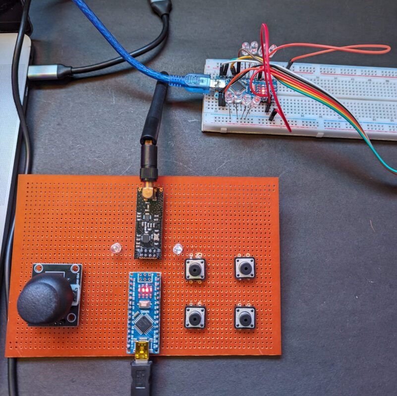
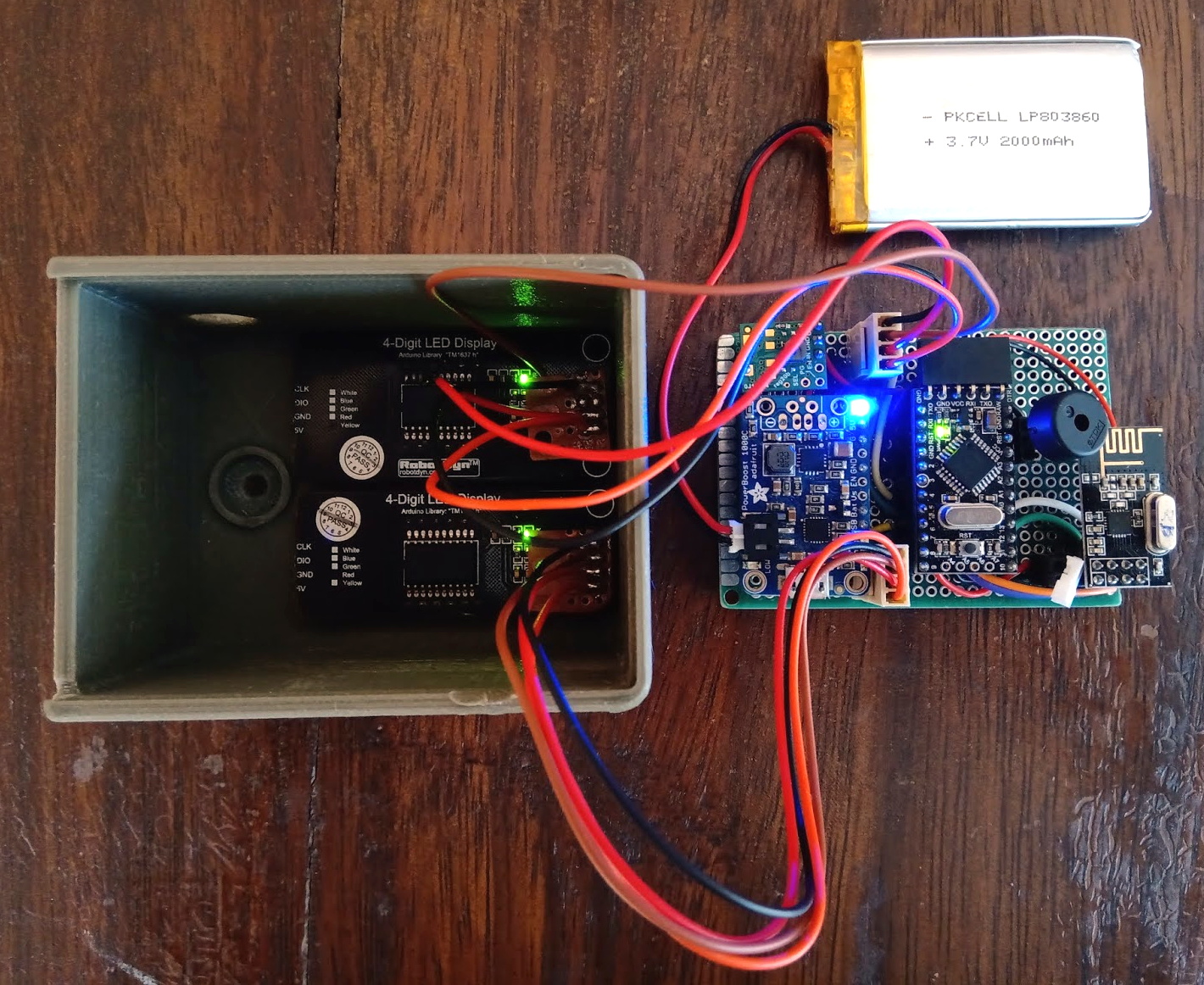
Here you can see both the circuit.

PCBWay PCB Prototyping Services

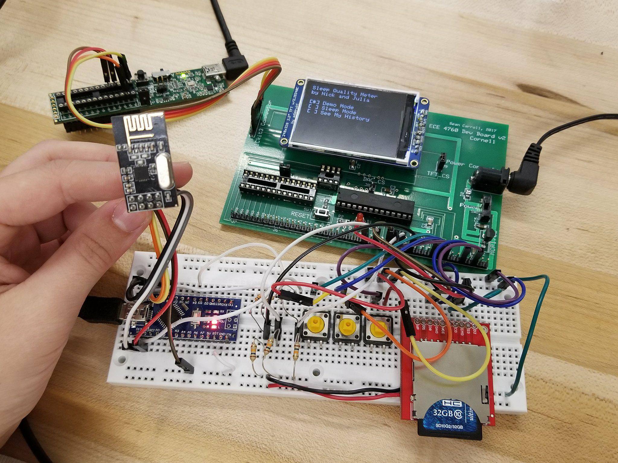
I have assembled the whole circuit on a breadboard. As you know breadboard assembly is not effective for this type of project. So, PCBWay offers Rapid PCB Prototyping for Your Research Work. I personally, recommend PCBWay because you can get your first-try boards right in 24 hours!

PCBWay website

The prototyping stage is the most critical period of time for engineers, students, and hobbyists. PCBWay not only makes your boards quick but also makes your job right as well as cost-effective. This greatly reduces your cost and shortens the time for developing your electronic

PCBWay can provide 2 Layer PCBs to highly advanced HDI and flex boards. Even though the PCBs they produce differ a lot regarding functionality and areas of use. I am impressed with the quality of the boards, the delivery time, and the cost-effectiveness

NRF 24L01 Remote Control working

When we plug both the circuit the transmitter and the receiver connect automatically to each other and start communicating transmitter continuously sends the data to the receiver. and the receiver compares that data with the condition if the condition true or not. in this NRF 24L01 Remote Control for RC Car only we need some basic components.

The post NRF Remote Control | NRF 24L01 Remote for Rc Car Plane appeared first on Techatronic.

It’s great to see people are out there trying to find fun ways to exercise amid the current crisis. Although jumping up and down isn’t great for the knees, it does give decent cardio. But if you don’t have a rope or a puddle, we admit that jumping can lose its bounce pretty fast.

Quarantine has been a game-filled time for [fridaay]. Somewhere between a handful of FPS games, he decided to try to play Google’s offline dinosaur-based side scroller game by making the dinosaur spring over the saguaros whenever he physically jumps in the air. (Video, embedded below.)

Here’s how it works: [fridaay] holds a transmit circuit that consists of an Arduino UNO, an accelerometer module, and an nRF24L01 transceiver, all running on a 9 V battery. Whenever [fridaay] jumps, the accelerometer reads the change in Z and sends it to the receiving circuit, which is just another UNO and nRF. The receiving UNO is connected to a laptop and configured to press the space bar so the dinosaur canters over the cacti.

We’ve never been able to stay alive long enough in the game to see this happen, but apparently you need to crouch at some point in the game. [fridaay] has yet to implement a control for that, but we’re sure he’ll think of something. Jump past the break to see the video, and hit him up if you need the code.

If you have a lot of parts at your disposal, why not make a physical version?

Via r/duino

[Miller] wanted to practice a bit with some wireless modules and wound up creating a robotic hand he could teleoperate with the help of a haptic glove. It lookes highly reproducible, as you can see the video, below the break.

The glove uses an Arduino’s analog to digital converter to read some flex sensors. Commercial flex sensors are pretty expensive, so he experimented with some homemade sensors. The ones with tin foil and graphite didn’t work well, but using some bent can metal worked better despite not having good resolution.

The wireless communications set up was pretty easy thanks to the NRF24L01 modules. The hard part was sewing the flex sensors into the glove. We thought some of the circuitry looked precarious on the glove, too.

For the robot hand, he used balsa wood and hinges for each joint. Flexible thread provided the return power like a spring. The hand was surprisingly artistic in a primitive sort of way.

While this is a cool demo, the hand isn’t likely to be practical for much as it is. Nerve impulses are better but harder. The glove reminded us a little of one we’d seen before.

Planning a game of Hacker Jeopardy at your next meetup? You’re going to want some proper buzzers to complete the experience, but why buy when you can build? [Flute Systems] has released an open source DIY game buzzer system based on the Arduino that will help instantly elevate your game. Certainly beats just yelling across the room.

The design has been made to be as easily replicable as possible: as long as you’ve got access to a 3D printer to run off the enclosures for the buzzers and base station, you’ll be able to follow along no problem. The rest of the project consists of modular components put together with jumper wires and scraps of perfboard. Granted it might not be the most elegant solution, but there’s something to be said for projects that beginners and old salts alike can complete.

Each buzzer consists of an Arduino Pro Mini 3.3 V, a nRF24L01, and of course a big pushbutton on the top. Each one is powered by a 110 mAh 3.7 V LiPo battery, though [Flute Systems] notes that the current version of the buzzer can’t actually recharge it. You’ll need to pull the pack out and charge it manually once and awhile. Thankfully, the printed enclosure features a very clever twist-lock mechanism which makes it easy to open anytime you need to poke at the internals.

The base station uses the 5 V version of the Pro Mini, with a Adafruit PowerBoost 1000C to step up the voltage from its 2,000 mAh battery. Of course it also has a nRF24L01, and also adds a buzzer and twin four digit seven-segment LED displays. [Flute Systems] says you can expect about five hours of runtime for the base station.

An especially nice feature of this setup is that the eight digit display allows the base station to show the number of each button in the order it was received. So rather than just getting a display of who buzzed in first, you can see the chronological order in which all eight buttons were pressed. Coming up with clever applications for this capability is left as an exercise for the reader.

Of course, there’s more than one way to build a buzzer. If you don’t like the way [Flute Systems] did it, then check out this version that uses 900 MHz radios and an OLED to show the results.

The field of radio control has benefited much from the onward march of technology. Where a basic 2-channel setup would once have cost hundreds of dollars, it’s now possible to get a high-end 2.4GHz 9-channel rig for well under $100, shipped to your door. However, the vast majority of these systems are closed-source and built for purpose. Sometimes, there are benefits to doing things your own way, and that’s precisely what this project does.

At its heart, it’s a simple combination. An Arduino Pro Mini talks to a NRF24L01 which handles the wireless communication. At that point, it’s up to you – throw in as few or as many controls as you like. For this build, [HowToMechatronics] has gone with a twin-stick setup, with a pair of potentiometers and twin toggle switches to round out the options.

The build comes in handy, as it’s possible to program in whatever features you may need for a given project. [HowToMechatronics] has used it to control a hexapod robot, among other projects. It’s a build that shows that with cheap and readily available parts, it’s possible to whip up a custom solution to suit your needs.

If this topic interests you.it’s worth saying that even those closed source radio control products can sometimes be hacked.

[Thanks to Baldpower for the tip!]

[Dickel] always liked tracked vehicles. Taking inspiration from the ‘Peacemaker’ tracked vehicle in Mad Max: Fury Road, he replicated it as the Mad Mech. The vehicle is remote-controlled and the tank treads are partly from a VEX robotics tank tread kit. Control is via a DIY wireless controller using an Arduino and NRF24L01 modules. The vehicle itself uses an Arduino UNO with an L298N motor driver. Power is from three Li-Po cells.

The real artistic work is in the body. [Dickel] used a papercraft tool called Pepakura (non-free software, but this Blender plugin is an alternative free approach) for the design to make the body out of thin cardboard. The cardboard design was then modified to make it match the body of the Peacemaker as much as possible. It was coated in fiberglass for strength, then the rest of the work was done with body filler and sanding for a smooth finish. After a few more details and a good paint job, it was ready to roll.

There’s a lot of great effort that went into this build, and [Dickel] shows his work and process on his project page and in the videos embedded below. The first video shows the finished Mad Mech being taken for some test drives. The second is a montage showing key parts of the build process.

Paper and cardboard are very versatile and accessible materials for making things. It’s what was used to do some target practice with this working paper and cardboard gun. With the right techniques foam core can be worked into an astonishing variety of shapes, and we also made a case for the value of a desktop vinyl cutter on any well-equipped hacker’s workbench.

An Arduino and a data radio can make a great remote sensor node. Often in such situations, the hardware ends up installed somewhere hard to get to – be it in a light fitting, behind a wall, or secreted somewhere outdoors. Not places that you’d want to squeeze a cable repeatedly into while debugging.

[2BitOrNot2Bit] decided this simply wouldn’t do, and decided to program the Arduinos over the air instead.

Using the NRF24L01 chip with the Arduino is a popular choice to add wireless communications to a small project. By installing one of these radios on both the remote hardware and a local Arduino connected to the programming computer, it’s possible to remotely flash the Arduino without any physical contact whatsoever using Optiboot.

The writeup is comprehensive and covers both the required hardware setup for both ends of the operation as well as how to install the relevant bootloaders. If you’re already using the NRF24L01 in your projects, this could be the ideal solution to your programming woes. Perhaps you’re using a different platform though – like an Arduino on WiFi? Don’t worry – you can do OTA updates that way, too.

While it can be difficult to get enough sleep, at least you can try to make it as restful as possible when you are in bed. That’s the idea behind this project by Julia Currie and Nicholas Sarkis, who developed an Arduino Nano-based sleep monitor for their final ECE 4760 project at Cornell.

The bulk of the monitoring device takes the form of a glove which measures heart rate using an IR sensor, along with movement via an accelerometer. Breathing is recorded using a conductive band wrapped around the user’s chest, which changes resistance depending on how it is stretched.

The Nano mounted to the glove collects this information, and transmits it wirelessly using an nRF24L01 chip to a PIC32 microprocessor on a base station. Data is then graphed nicely on a TFT display for further analysis.

You can read more about the project here and see the video below!

[William Osman] set out to prove that unlike expensive commercial data logging rigs, he could get the same results for under twenty bucks. He wanted to build a wireless three-axis accelerometer for a race car project, allowing engineers to make modifications to the suspension based on the data collected.

The hardware consists of an Arduino Pro Mini connected to a three-axis accelerometer, and an nRF24L01 wireless module. Power is supplied by the race car’s 12 V, changed to 5 V by a linear regulator with the Pro Mini in turn supplying 3.3 V. The base station consists of an Arduino and another nRF24L01 module plugged into a laptop.

The telemetry system is based on COSMOS, an open-source, realtime datalogging platform put out by Bell Aerospace. COSMOS consists of fifteen separate applications depending on how you want to view and manage your telemetry. You can download [William]’s COSMOS config files and Arduino sketch on Google Docs.

We’ve published a bunch of pieces on telemetry, like this ESP8266 telemetry project, a rocket telemetry rig, and open sourcing satellite telemetry.

[Thanks, Dennis Nestor!]


Filed under: Arduino Hacks


  • Newsletter

    Sign up for the PlanetArduino Newsletter, which delivers the most popular articles via e-mail to your inbox every week. Just fill in the information below and submit.

  • Like Us on Facebook