Posts | Comments

Planet Arduino

Archive for the ‘Nano’ Category

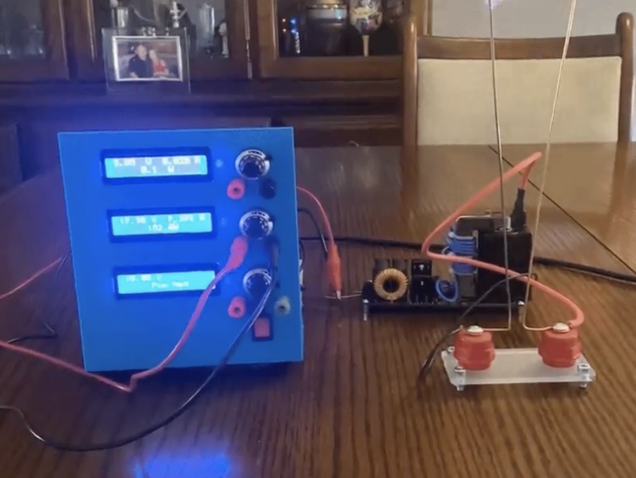
Every maker should have a bench power supply in their possession, ready to provide whatever voltage a project or particular component requires. But not all bench power supplies are created equal. Some only have a single output, some have a limited voltage range, and some can’t handle much current. In an attempt to eliminate such concerns forever, Doug Domke built “the Beast.”

This is a beefy bench power supply that can easily handle any project an electronics tinkerer is likely to tackle. It has three outputs that can all operate at the same time. Two of them can be set anywhere from 2V to 30V and can supply up to 10A each, at 30V. However, the supply transformer is only rated for 240 watts. If both are pulling the full current, then setting them above 24V would exceed the rating. But that isn’t a situation many people will find themselves in. The third output comes from a 20W supply that can provide 3V to 30V (positive or negative).

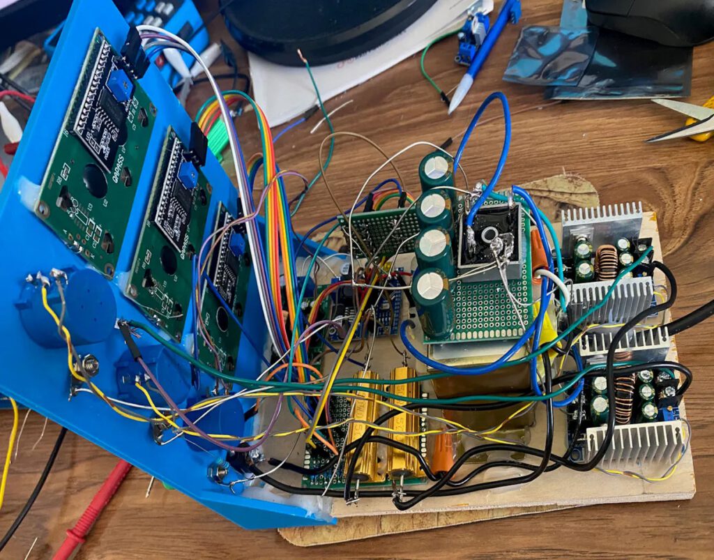
The user sets each output’s voltage with a simple potentiometer, but an Arduino Nano monitors the voltage and current of each using the analog input pins. The maximum 30V is far too high for the Arduino to work with directly, so it takes measurements through voltage dividers. With voltage and current readings, the Arduino can then calculate wattage. It displays the information for each output on a dedicated 16×2 character LCD screen, connected via I2C. 

If you’re in need of a robust bench power supply, the Beast may just fit the bill.

The post This beastly DIY bench power supply will satisfy any requirement appeared first on Arduino Blog.

If you’ve ever tried to produce an analog video signal with an Arduino, then you know that it isn’t easy. That’s a bit counterintuitive if you think of analog video as “old” and assume that generating an analog video signal would be trivial with our powerful modern hardware. But there are many ways in which analog signals are tricky and that’s especially true if you want something like VGA output, which requires very precise timing. That’s why it is so impressive that Slu4 was able to build this retro computer with just an Arduino Nano and a shift register.

This was no simple feat and it really showcases Slu4’s programming prowess. His creation can output 320×200 resolution VGA video while reading PS/2 keyboard inputs, with enough processing power leftover to handle basic video game logic and graphics. He demonstrates that with a Tetris­-like games that runs very smoothly. And Slu4 says that it is even possible to add 16 colors per row, though he doesn’t show that in action.

Slu4 first achieved a similar result a few years ago, but that required several IC (Integrated Circuit) chips. This version only needs one: a standard 74HC166 shift register. That helped him overcome some of the challenges related to VGA timing, which the Nano’s ATmega328 microcontroller can just barely keep up with. This did necessitate some low-level programming to maximize efficiency, but Slu4 was able to pull it off. Even more impressive, he was able to read PS/2 keyboard input at the same time so the player can control the game. 

The post A shift register is all you need to build an Arduino Nano-based retro computer appeared first on Arduino Blog.

How do unstable things stay upright? True passive balancing is very difficult and isn’t dynamic, so it doesn’t help when there is movement. Active balancing is all about inertia and this is how a tightrope walker can traverse a chasm by making small adjustments with a long pole. This is the same principle behind “self-balancing robots” that utilize reaction wheels. But the control scheme necessary to get that right is very difficult to perfect, as demonstrated by Nikodem Bartnik’s project that was three years in the making.

Physically, this is about as simple as a self-balancing robot can be. It stands on a single foot designed to be unstable in one horizontal axis, but stable in the other. It is long, front-to-back, so the robot can’t tip forward or backward. But the bottom of the foot has a curve to it, so it can’t stand upright without tipping to one side or the other. A reaction wheel with bolts for weights is responsible for preventing that tipping.

This is supposed to work by spinning in order to “push” against nothing (thanks to inertia), which generates torque to stop the tip. But Bartnik’ discovered that it was a massive challenge to tune that spin.

An Arduino Nano board controls a small brushless DC motor that spins the reaction wheel. A gyroscope sensor lets the Arduino monitor tilt and power comes from a hobby LiPo battery. The Arduino utilizes PID (proportional-integral-derivative) algorithms to try an apply just enough spin to counteract tipping, but not so much that it overcorrects.

That’s where Bartnik ran into trouble, because PID tuning is hard. Each variable has to be at the exact value—relative to the others — for PID to work as intended. After countless hours of struggling, Bartnik added a Bluetooth module to the Arduino to change those values wirelessly without flashing new code every time. That sped up the process dramatically, allowing Bartnik to find a set of values that works pretty well to keep the robot upright.

The post A three-year journey to build a reaction wheel appeared first on Arduino Blog.

When you hear the word “joystick,” you probably think of the standard dual-axis joysticks that we see on video game controllers. As the name implies, those move and provide signals for two axes (X and Y). But there is no reason that a joystick needs two axes and, in fact, that may not be desirable. To demonstrate the practicality of single-axis joysticks, Austin Allen built this simple controller suitable for several different applications.

Allen’s device controls three different things with its three single-axis joysticks: an RGB LED, a servo motor, and a stepper motor. Each of those is an example of a single-axis at work. That axis maps to color (red and green) and brightness for the LED, horn position for the servo, and rotation direction/speed for the stepper motor. There are, of course, several other viable use cases for single-axis joysticks.

To showcase this, Allen’s unit provides signals to an Arduino Nano board, which then controls the LED and motors. It controls the LED and servo motor directly, but goes through a TMC2208 driver to handle the stepper motor. The signals from the joysticks are easy to read, because they’re just potentiometers. Each joystick accepts positive and negative power, then outputs a voltage between those two based on its position. With a standard analogRead() function, the Arduino can check the voltage and determine the joystick position.

You may not have any use for this specific controller, but it does do a good job of illustrating potential applications for single-axis joysticks and you should consider them for future projects.

The post Don’t ignore single-axis joysticks appeared first on Arduino Blog.

The Tesla coil, patented by legendary inventor Nikola Tesla in 1891, is a kind of resonant transformer circuit capable of producing sparks of high-voltage alternating-current electricity. They don’t have many practical uses today beyond novelty, but they were commonly used in spark-gap radio transmitters in the early 20th century. The sparks generated by a Tesla coil would emit strong bursts of radio waves and operators could encode information through patterns of pulses, similar to a wired telegraph. But those sparks are difficult to control, which is why Mirko Pavleski designed this Arduino-based “staccato” controller for Tesla coils.

The purpose of Pavleski’s device is to gain better control over a Tesla coil, with the goal of generating longer sparks with less power. It does so by providing very granular control over the length of each pulse, its intensity, and the interval between pulses. A Tesla coil requires a lot of voltage to create a spark, but very little current. That means that the total power needed to produce a spark is minimal and relatively safe to oversee with a microcontroller.

In this case, Pavleski used an Arduino Nano to manage the circuit. A control panel lets the user adjust the parameters, then the Arduino does the rest. Power comes in from mains via a 12V transformer and the Arduino controls the current going from that to the Tesla coil with a standard triac, with a large capacitor providing some filtering. Almost everything else comes down to the Arduino’s programming, which ultimately determines the characteristics of the electricity supplied to the Tesla coil. Because that’s going through a triac, the Arduino can “dim” the voltage, as opposed to simply toggling it like a relay would.

This will let Pavleski perform more in-depth experiments with Tesla coils.

The post DIY “Staccato” controller drives Tesla coils appeared first on Arduino Blog.

If you have an interest in robotics, it can be really difficult to know where to start. There are so many designs and kits out there that it becomes overwhelming. But it is best to start with the basics and then expand from there after you learn the ropes. One way to do that is by building MertArduino’s adorable app-controlled robot dog.

This is a little more complex than a typical line-following rover kit, but it is still approachable for beginners. It uses eight inexpensive MG90S hobby servo motors to walk on four legs, plus one more servo to rotate the head. The tutorial explains how to create a smartphone app for controlling the robot and there is an ultrasonic sensor hidden in the dog’s eyes to help it detect obstacles. 

To construct this robot, you will first need to 3D print the body, legs, and head. Those parts are small enough to print on almost any model of 3D printer. You’ll then need the custom PCB, onto which all of the electronic components attach. You can order that from any PCB fabrication service. Using basic through-hole soldering techniques, you can populate that PCB with an Arduino Nano board, an HC-05 Bluetooth module (for communication with a smartphone), and various miscellaneous components like resistors and a voltage regulator. Power comes from a pair of 18650 lithium battery cells.

After assembly, you can begin controlling the robot using the provided app. Or you can follow the instructions to make your own app with the help of MIT’s handy block-based Scratch programming tool.

If you want to dip your toes into the world of robotics, this seems to be a fun way to do it.

The post Build yourself this simple app-controlled robot dog appeared first on Arduino Blog.

It is amazing how much technological progress humanity has achieved over the past few centuries. But while our capability with electronics has shot ahead, it seems that we’ve almost regressed when it comes to mechanical and electromechanical design. Watches and clocks are great examples of this, as pre-digital craftsmen were capable of astonishing feats that are still impressive today. But some people are keeping those traditions alive, as evidenced by this mechanical seven-segment display clock driven by a single stepper motor.

This clock is truly a work of art. It shows the time across six digits, each of which is a seven-segment display. But those aren’t segments lit by LEDs, they’re physical pieces of plastic. A complex series of gears flips them in and out in the appropriate sequence to display the numeric characters. That is very impressive when you consider that the segments don’t actuate in an order that correlates with the numerical value — the number 4 isn’t simply turning “on” one more segment than the number 3. But even so, the clock progresses through the numbers in order.

That’s only possible because of the genius mechanical design of the clock. Further increasing the wonder is the fact that the clock and all of its parts were 3D-printed — no precision machining necessary. An Arduino Nano board controls the stepper motor that drives the whole series of gears. That ensures that the motor turns at a constant rate, which is required to keep accurate time.

The post A single stepper motor drives this mechanical seven-segment display clock appeared first on Arduino Blog.

If you’re ever driving through rural Finland about an hour south of Jyväskylä, you might come across the Haihatus art center. That includes KITA, “the house of kinetic arts.” You’ll recognize it right away by its bold swaths of vibrant paint. And if you come by at night, you’ll see the snow illuminated in dancing colors by a kinetic art installation built by Niklas Roy and Kati Hyyppä.

Because the building is unheated and can reach temperatures as low as -30°C (-22°F), KITA remains closed through the winter. Roy and Hyyppä approached this project with the goal of turning the building itself into a kinetic art piece for people to enjoy through the cold months. To achieve that, they lit the windows and added movement. Lights inside the building move along tracks and motors pull them with spools of twine. An Arduino Nano development board controls the motors through H-bridge drivers. Various reflectors and filters alter the lights as they move.

To make that even more dynamic, they animated the illumination and introduced sound. A control box built into an old tool case contains another Arduino Nano that can switch the lights through relays. That Arduino also generates sounds and melodies from algorithms based on random inputs, but synced to the lights. 

This project came with unique challenges related to the weather, as many electronic components act unpredictably at these extreme temperatures. But the installation worked well enough to unveil on New Year’s Eve 2023, when the people living in the town of Joutsa got to enjoy the dazzling inauguration.

The post This kinetic light installation illuminates the Finnish snow appeared first on Arduino Blog.

Henry Evans suffered a brain-stem stroke 20 years ago that left him paralyzed with quadriplegia. He can move his head, but other than a small amount of movement in his left thumb, he can’t control the rest of his body. To help Evans live a more independent life, researchers from Carnegie Mellon University’s School of Computer Science developed a motion control interface that lets him operate a mobile robot.

The robot is a Stretch model from Hello Robot, which can navigate a home on its mobile base, interact with objects using its arm and gripper, and provide a live view through a pair of cameras (one on its head and one on its gripper). But this telepresence robot doesn’t have any provisions for operation by a person with quadriplegia like Evans. That’s where the SCS team came in.

They created a head-worn motion control interface consisting of an Arduino Nano board, a Bosch BNO055 IMU and an HC-05 Bluetooth module. The Arduino monitors Evans’s head movement with the IMU, then sends cursor movement commands over Bluetooth to the computer running the software that controls the Stretch robot. That lets Evans move the cursor on the screen, and then he can click a mouse button thanks to the limited movement of his left thumb.

During a week-long testing session, Evans successfully used this system to perform many tasks around his home. He was able to use the robot to pick up tissues and bring them to his face, and even to adjust the blinds on his bedroom window. Clever “Drivers Assistance” software lets the robot operate semi-autonomously in order to complete tasks that would have been difficult for Evans to accomplish through manual control.

While the Stretch robot is expensive at about $25,000 dollars, the HAT (Head-worn Assistive Teleoperation) control interface is affordable. This is just a prototype, but a device like this could help many people around the world living with quadriplegia and other conditions that affect motor control.  

The post Motion control interface facilitates robot operation for those with paralysis appeared first on Arduino Blog.


  • Newsletter

    Sign up for the PlanetArduino Newsletter, which delivers the most popular articles via e-mail to your inbox every week. Just fill in the information below and submit.

  • Like Us on Facebook