Posts | Comments

Planet Arduino

Archive for the ‘Nano’ Category

As a society, we have decided to enact some measures to make our world more accessible to those with disabilities. Wheelchair ramps, for example, are often legal requirements for businesses in many countries. But we tend to drop the ball when it comes to things aren’t necessities. For instance, entertainment options are an afterthought much of the time. That’s why Alain Mauer developed this LED gaming platform for people with special needs.

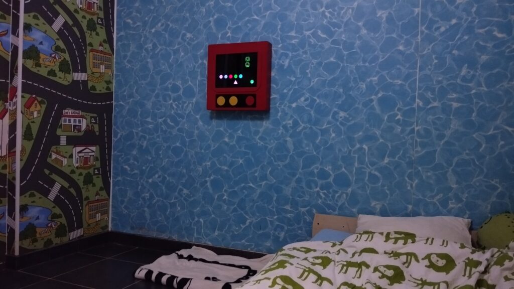
This device offers a lot of flexibility so that builders can tailor it to a specific individual’s own needs and tastes. Mauer designed it for his son, who is 17 years old and lives with non-verbal autism. Entertainment options intended for neurotypical people don’t engage the teen, but toys designed for children fail to hold his interest for long. This game, dubbed “Scott’s Arcade,” is simple to understand and interact with, while still offering a lot of replayability. It is also durable and able to withstand rough handling.

Scott’s Arcade consists of a “screen” made up of individually addressable RGB LEDs and a faceplate with shape cutouts that act as masks for the LEDs. An Arduino Nano controls the lights and responds to presses of the large buttons beneath the screen. It can trigger sound effects through a DFRobot DFPlayer Mini MP3 player as well.

Mauer programmed a few simple games for the device, such as a matching game that challenges the player to find the circle of the same color as the triangle. When they succeed, they’re rewarded with fanfare sound effects and flashing lights. Makers can also program their own games to suit the players’ abilities and interests. 

The post A gaming platform tailored to those with special needs appeared first on Arduino Blog.

Pinball machines are prime examples of the dizzying heights achieved by engineers in the electromechanical era before digital electronics came along. But while those classic pinball machines are extremely impressive from an engineering standpoint, they required an immense amount of expertise and were therefore unapproachable to most. By utilizing modern digital components like Arduino development boards, Barjo was able to construct this amazing Jurassic Park-themed pinball machine.

From a user perspective, this looks and operates a lot like a classic pinball machine. But instead of relying on complex mechanical linkages and vast arrays of electric switches, it takes advantage of today’s microcontrollers and sensors. The table is mostly wood and Barjo 3D-printed a bunch of custom parts, such as the paddles, pathways for the ball, and enclosures for the electronic components. 

Some of the parts, like the spring-loaded ball launcher, are standard off-the-shelf pinball components that are available through retailers that sell refurbishment parts. But most are custom and work using electronic circuitry. The electronic components operate under the control of an Arduino Nano and an Arduino Mega 2560. The Nano is tasked with the flippers, while the Mega handles the displays, sensors, and solenoids.

There are a variety of sensors on the table, such as infrared break beam sensors to detect the passing ball. Those can trigger solenoids to open up gates to specific pathways, like the T-Rex paddock that lets the player rack up additional points. Those points, and some status information, show up on an eight-digit seven-segment display. And, of course, there are plenty of flashing lights to create the ideal pinball experience.

The post This DIY Jurassic Park pinball machine is a T-Rexcellent use of Arduino appeared first on Arduino Blog.

Weather stations are very popular projects for people new to Arduino. They’re complex eno­­­ugh to help a person learn new skills, but they’re simple enough to be approachable. However, that popularity has led to something of an arms race, with many makers attempting to design the most impressive weather stations on the internet. If you want to go back to the basics to dip your toes into the water, Mirko Pavleski explains how to build a classic weather station that prioritizes the essentials.

Inspired by older devices that displayed information like temperature, barometric pressure, and humidity on analog gauges, Pavleski chose a design with three screens in a vertical stack. Each screen can display whatever data the user can access through a sensor. In this case, his station utilizes the popular BME280 module that monitors the same three parameters as the vintage inspiration: temperature, pressure, and humidity. 

This weather station shows each reading on a small two-tone OLED screen. Those screens have yellow pixels on the top and blue pixels on the bottom, which is handy for distinguishing the title from the data without the expense or complexity of a full-color screen.

An Arduino Nano board reads the data from the BME280 sensor and writes to the displays. But those displays and the BME280 all connect through I2C. To interface with all of them through the single pair of SCL/SDA pins, Pavleski included a TCA9548a multiplexer module. 

Those components all mount in a minimalist enclosure made from foam board. And while we certainly enjoy complex weather stations, we appreciate the simplicity and approachability of this design.

The post This classic weather station prioritizes the essentials appeared first on Arduino Blog.

If you only care about showing content as clearly as possible at the lowest cost, then you’ll want to turn to LCD or OLED technology. But a project’s display gives you an opportunity to get creative with the aesthetic, which opens up a whole world of different display types. If you want a retro feel, then you can inspiration in DIY GUY Chris’s gorgeous LED matrix.

This is a dot-matrix LED display with an overall resolution of 32×8. But that description alone doesn’t do the project justice. Chris used tiny 0603 SMD LEDs, which allowed for very high “pixel” density and that results in better clarity than a typical LED matrix display. To enable future expansion, Chris set this up as a host board that accepts four LED boards — each of which contains an 8×8 matrix. A MAX7219 IC drives the LEDs on each of those boards.

The LED boards connect to the host board through nifty mezzanine connectors. The host board contains an Arduino Nano that sends control signals to the MAX7219 chips. The Arduino can supply USB power to the LEDs, but there is also a DC jack for power when USB isn’t connected. Chris’s Arduino sketch lets the user “print” alphanumeric characters to scroll across the four LED matrices.

The best part about this design (other than the great style) is that Chris can scale it up in the future with larger host boards that accept more than four LED boards.

The post This gorgeous LED matrix display will wow you appeared first on Arduino Blog.

Design paradigms are the norm in every industry and automated machine tools aren’t any different. Most 3D printers, for example, function in a similar way: each axis rides on rails, with belts pulled by fixed motors. Pen plotters tend to utilize similar kinematics. But sometimes we see builds that ignore established paradigms, like this DIY fixed-belt CNC pen plotter.

Unlike most pen plotters, this machine moves along fixed belts. This layout treats the belts almost like rigid bodies, similar to a rack-and-pinion gear set. Because the belts remain fixed in place, the motors must move. The result is a unique form factor. In this case, creator tuenhidiy made heavy use of PVC pipe for the machine’s structure and enclosures. The materials are very inexpensive, but this machine’s axes ride on hardened steel rods and so it is still capable of drawing very well.

To keep costs down without sacrificing capability, tuenhidiy chose to use an Arduino UNO Rev3 board for control. That reads GRBL G-code files through a microSD card module and controls the stepper motors through a CNC shield with A4988 stepper drivers. There is also a simple Arduino Nano-based controller interface made with a 16×2 character LCD, button, and rotary encoder.

This will work with a variety of different open-source software tools, including popular plugins for Inkscape. 

The post Affordable fixed-belt CNC plotter runs on Arduino appeared first on Arduino Blog.

20 years ago, you could walk into any pharmacy or big box store with your rolls of film, then get developed photos back within 24 hours at a reasonable price. But that industry is dead and life is much more difficult for film photographers today. While big chain pharmacies still have developing services, they have to send the film out to a lab and it is quite an expensive. One alternative is to build the OpenAutoLab, which can automatically develop black-and-white and color film photos without user interruption.

The OpenAutoLab machine only develops film and so you’ll still need to turn elsewhere to get your prints, but it makes the process much easier to perform at home. It handles most of the steps you would need to do in a dark room, so you aren’t fumbling around with baths and washes. It pumps the chemicals back and forth as needed and, most importantly, maintains the ideal temperature and performs periodic agitation.

An Arduino Nano board is responsible for most of the process control. It opens and closes the valves and operates the pump. It monitors each reservoir with a load cell and HX711 amplifier or float switch, moving the liquids back and forth at specific times according to the user-set parameters. Interestingly, the designers chose to use a sous vide stick to maintain temperature and circulate the bath. That’s a clever idea, because those sous vide sticks are very affordable and quite precise. 

OpenAutoLab is intended to be a more affordable alternative to the Jobo Autolab and it appears to have promise. Documentation is sparse at the moment and we aren’t sure how well it works, but brave photographers can use the build instructions to try out OpenAutoLab right now.

The post OpenAutoLab lets you automatically develop photos at home appeared first on Arduino Blog.

With Christmas just around the corner, you may start reminiscing about childhood races down the stairs to rip open presents under the tree. You’ll likely never do be any faster than you were when you were 12, but why not turn stair racing into an event anyway? Jared Dilley made that possible with his stairway stopwatch device.

It seems prudent to give you a disclaimer here: running up and down stairs is dangerous. We promise that your bones aren’t nearly as resilient as they were when you were a kid.

Dilley’s device is a timer system meant to measure the time it takes to ascend or descend a flight of stairs. It could also be used for races across flat ground or any other kind of terrain. That’s because it consists of two separate units that act as race gates. Each has an ultrasonic sensor to detect a passing person. Together, they measure the time it takes to pass the second gate after triggering the first.

Each unit contains an Arduino Nano board and the two boards communicate via HC-12 433MHz radio transceiver modules. Those have enough range to allow for positioning anywhere within a house, assuming you don’t live in a mansion with multiple wings. The primary unit displays the current record on a small LCD screen, as well as the most recent time on a large LED matrix panel. Both the primary and secondary units have nifty 3D-printed enclosures that Dilley designed to mount onto walls.

If you want to start your own racing career, all of the design files are available on GitHub.

The post Stairway stopwatch tracks climb time appeared first on Arduino Blog.

A drill press is a very useful tool that lets you slowly drill holes that are perfectly perpendicular to the work piece. And good drill presses give you a readout that lets you drill to a precise depth. But the cheap drill press stands for hand drills make that difficult. To solve this problem on a budget, Minikk designed an affordable digital readout add-on.

This digital readout is very useful. It shows exactly how far you move the drill, with a precision of 0.01 millimeters. And it lets you set the zero point (typically the top surface of the material) so you don’t have to do any math in your head.

Minikk achieved this with an inexpensive digital caliper. That has an LCD screen without a backlight and it is hard to read, so Minikk hacked it with an Arduino Nano board to add a much more readable OLED screen. That was possible because this digital caliper, like most of the budget models on the market, has a control board that is accessible via I2C. That lets the Arduino pull the measurements to display on the OLED.

With a 3D-printed mount and enclosure to hold everything in place, Minikk now has a reasonably accurate and precise digital readout that didn’t break the back. This lets them drill holes to exactly the required depth without any hassle. Best of all, Minikk uploaded the sketch and 3D files so you can add a digital readout to your drill press.

The post Add an inexpensive digital readout to your drill press appeared first on Arduino Blog.

GPIO pins on most microcontrollers operate at low voltages, typically between 3.3V and 5V, and are unable to deliver much current — oftentimes stopping at 20-40mA. This is why, when setting up an LED, series resistors are used to limit the amount of current draw and prevent damage to the pin. Mirko Pavleski created a workbench device that helps figure out the size of this resistor and allows for an LED to be connected for live testing.

Built around an Arduino Nano, the system presents the user with a display for selecting the desired maximum current draw and LED voltage input. The panel of buttons on the left can increment or decrement the ideal voltage/current levels that, in turn, are then used to calculate the value of the series resistor. This value appears on the bottom alongside the part number for ordering the resistor from a distributor.

The values at the top of the LCD indicate how the connected LED currently behaves given a known voltage. By wiring the LED to a couple of sense resistors and an analog input pin, its forward voltage along with its current draw can be determined.

More details about this project can be found in Pavleski’s Hackaday.io write-up here.

The post This DIY tool automates LED testing and current limit calculations appeared first on Arduino Blog.

Most of us don’t use label stickers very often, so we can afford to spend several minutes fumbling around with corners to try and peel the labels from their backing paper. But if you’re handling many of them a day, like putting “fragile” stickers on shipping boxes, then that inefficient fumbling will be an issue. To make life easier for you, Mr Innovative built this simple machine that quickly dispenses labels.

Mr Innovative designed this machine for the kinds of label stickers that come on rolls of backing paper. It should work with a wide range of roll sizes and the dimensions are easy to modify if you need to accommodate even larger rolls. The best part is that it doesn’t require any configuration. The machine will pull the paper backing around a roller, releasing the sticker. That causes the sticker to cover an infrared sensor and the machine stops. After the user removes that sticker, the machine pulls the paper backing again until the next sticker is ready.

As with most of Mr Innovative’s projects, this utilizes a custom multipurpose control board that hosts an Arduino Nano board. That drives a single stepper motor, which rotates a spool to pull the backing paper from the roll of labels. The machine’s mechanical parts are all either 3D-printable, off-the-shelf hardware and fasteners, or standard 2020 T-slot aluminum extrusion.

The post This simple machine quickly dispenses labels appeared first on Arduino Blog.


  • Newsletter

    Sign up for the PlanetArduino Newsletter, which delivers the most popular articles via e-mail to your inbox every week. Just fill in the information below and submit.

  • Like Us on Facebook