Posts | Comments

Planet Arduino

Archive for the ‘ATtiny Hacks’ Category

Over the years we’ve seen plenty of homebrew handheld game systems that combine an AVR microcontroller, a few buttons, and an small OLED display. We’ve even seen some of them turned into commercial products, such as the Arduboy. They’re simple, cheap, and with the right software, a lot of fun. But being based on an MCU, most of them share the same limitation of only being able to hold a single game at any one time.

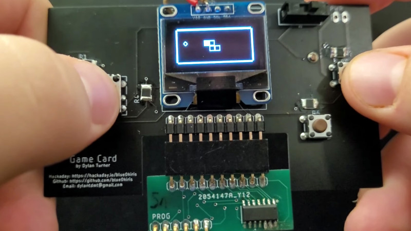
But not the Game Card, by [Dylan Turner]. This handheld was specifically designed so that games could be easily swapped out using physical cartridges. But rather than trying to get the system’s microcontroller to boot code from an external flash chip, the system relocates the MCU to the removable cartridge. That might seem a bit overkill, but given how cheap the ATTINY84A on each cartridge is, it’s not exactly going to break the bank.

With the microcontroller on the cartridge, the only hardware that stays behind on the Game Card is the SSD1306 128×64 OLED display, buttons, and the battery. That means the handheld is effectively non-functional unless a game is slotted in, but that could be said of most early cartridge-based game systems as well. On the other hand, it also opens up the possibility of producing cartridges with more powerful microcontrollers down the line.

Using a different microcontroller for each game is a neat hack, but it’s not the only solution to the problem. We previously saw a community effort to add expandable storage to the Arduboy in the form of a DIY cartridge, which ultimately led to the development of an official flash chip upgrade for the handheld.

You would think the hard part about creating a spectrum analyzer using a pint-sized ATTiny85 would be the software. But for [tuenhidiy], we suspect the hard part was fabricating an array of 320 LEDs that the little processor can drive. The design does work though, as you can see in the video below.

The key is to use a TPIC6B595N which is an 8-bit shift register made to drive non-logic outputs. With all outputs on, the driving FETs can supply 150 mA per channel and the device can handle 500 mA per channel peak. At room temperature, the part can go over 1W of total power dissipation, although that goes down with temperature, of course. If you need higher power, there’s a DW-variant of the part that can handle a few hundred milliwatts more.

A fixed-point FFT library does the actual work. The program simply reads samples, processes the FFT, and drives the LEDs through the shift registers.

The construction technique is also a bit interesting as much of the wiring is left over LED leads. We admire the neat work, but we think we’d have had better luck with PCB traces.

Although billed as a spectrum analyzer, a device like this is really more of a music visualizer. If you want a real spectrum analyzer, they have become reasonably cheap. As impractical as the LED grid is for practical output, it beats ping pong balls.

400

As every Hackaday reader knows, and tells us at every opportunity in the comments, adding an Arduino to your project instantly makes it twice as cool. But what if, in the course of adding an Arduino to your project, you run into a problem and need to debug the code? What if you could use a second Arduino to debug the first? That would bring your project up to two Arduinos, instantly making it four times as awesome as before you started! Who could say no to such exponential gains?

Debugging an ATTiny85

Not [Wayne Holder], that’s for sure. He writes in to let us know about a project he’s been working on for a while that allows you to debug the execution of code on an Arduino with a second Arduino. In fact, the target chip could even be another AVR series microcontroller such as a the ATTiny85. With his software you can single-step through the code, view and modify values in memory, set breakpoints, and even disassemble the code. Not everything is working fully yet, but what he has so far is very impressive.

The trick is exploiting a feature known as “debugWIRE” that’s included in many AVR microcontrollers. Unfortunately documentation on this feature is hard to come by, but with some work [Wayne] has managed to figure out how most of it works and create an Arduino Sketch that lets the user interact with the target chip using a simple menu system over the serial monitor, similar to the Bus Pirate.

[Wayne] goes into plenty of detail on his site and in the video included after the break, showing many of the functions he’s got working so far in his software against an ATTiny85. If you spend a lot of time working on AVR projects, this looks like something you might want to keep installed on an Arduino in your tool bag for the future.

Debugging microcontroller projects can be a huge time saver when your code starts running on real hardware, but often takes some hacking to get working.

We didn’t include a “Most Ornate” category in this year’s Coin Cell Challenge, but if we had, the environmentally reactive jewelry created by [Maxim Krentovskiy] would certainly be the one to beat. Combining traditional jewelry materials with an Arduino-compatible microcontroller, RGB LEDs, and environmental sensors; the pieces are able to glow and change color based on environmental factors. Sort of like a “mood ring” for the microcontroller generation.

[Maxim] originally looked for a turn-key solution for his reactive jewelry project, but found that everything out there wasn’t quite what he was looking for. It was all either too big or too complicated. His list of requirements was relatively short and existing MCU boards were simply designed for more than what he needed.

On his 30 x 30 mm PCB [Maxim] has included the bare essentials to get an environmentally aware wearable up and running. Alongside the ATtiny85 MCU is a handful of RGB LEDs (with expansion capability to add more), as well as analog light and temperature sensors. With data from the sensors, the ATtiny85 can come up with different colors and blink frequencies for the LEDs, ranging from a randomized light show to a useful interpretation of the local environment.

It’s not much of a stretch to imagine practical applications for this technology. Consider a bracelet that starts flashing red when the wearer’s body temperature gets too high. Making assistive technology visually appealing is always a challenge, and there’s undoubtedly a market for pieces of jewelry that can communicate a person’s physical condition even when they themselves may be unable to.

Form or function, life saving or complete novelty, there’s still time to enter your own project in the 2017 Coin Cell Challenge.


Filed under: Arduino Hacks, ATtiny Hacks, contests, Wearable Hacks

The Raspberry Pi was made to be inexpensive with an eye toward putting them into schools. But what about programs targeted at teaching embedded programming? There are plenty of fiscally-starved schools all over the world, and it isn’t uncommon for teachers to buy supplies out of their own pockets. What could you do with a board that cost just one dollar?

That’s the idea behind the team promoting the “One Dollar Board” (we don’t know why they didn’t call it a buck board). The idea is to produce a Creative Commons design for a simple microcontroller board that only costs a dollar. You can see a video about the project, below.

Despite being licensed under Creative Commons, there isn’t much detail available that we could find. It appears the board uses an 8 pin Atmel CPU (and the FAQ indicates that the board will use the Arduino IDE). We’re guessing that it’s essentially a Digispark / Adafruit Trinket / ATtiny85 with V-USB installed.

The crowdfunding campaign page lists the following details:

  • CPU: 8-bit
  • GPIO (input and output ports): 6
  • USB Interface: Yes
  • Memory: Flash 8 kBytes (expandable to 256 kBytes)
  • Spaces for expansions: WiFi ESP8266, Memory 24C256, H bridge L293
  • Voltage: 5V
  • Indicator LEDs: 2
  • Reset Button: Yes
  • Fitting Spaces: 4 (compatible with Arduíno UNO or similar)
  • Quick Guide: The English board comes with a printed guide in other languages.

If it is an ATTtiny85-based design, two of those “GPIO” pins will be eaten up by the USB programmer, and maybe two more by the indicator LEDs. And some of that 8 kB of flash is consumed by the bootloader. In short, it’s not going to be able to do everything all at once. Still, it could be just the thing for getting your feet wet.

But the real story is the price. The dollar price tag doesn’t include shipping or taxes, of course, but even getting the price down that low is impressive. Time will tell if the market has an appetite for a dollar board. If we had to guess, the real value will be in ready-made course material.

There are plenty of educational boards out there, but few (if any) cost a buck.


Filed under: Arduino Hacks, ATtiny Hacks, Crowd Funding

[Joedefa] had a Griffin Beacon Universal Remote that was collecting dust, and decided that it needed to stop collecting dust. He had a growing number of wireless devices in his house and found himself in need of a remote to control them all. The Griffin Beacon fit the bill, but most of his lights and outlets were RF controlled. So he did what hackers do best… broke out the screw driver and soldering iron and rewired it!

[Joedefa] is using an Attiny85 as the brains between an infrared LED and a RF transmit module (if anyone can identify the source of this module, please let everyone know in the comments).  A pair of red and green LEDs lets him know if the remote has received commands successfully.

It’s always nice to see a discontinued product made useful once more with a little ingenuity and an Arduino some hacking skill. Hat’s off to [Joedefa] for a righteous hack!


Filed under: Arduino Hacks, ATtiny Hacks
Oct
23

Now Let’s See The World’s Largest Arduino

arduino, arduino hacks, attiny, ATtiny Hacks, ATTINY85, smallest arduino Comments Off on Now Let’s See The World’s Largest Arduino 

atomsoft

A few days ago we saw what would have been a killer Kickstarter a few years ago. It was the smallest conceivable ATtiny85 microcontroller board, with resistors, diodes, a USB connector, and eight pins for plugging into a breadboard. It’s a shame this design wasn’t around for the great Arduino Minification of Kickstarter in late 2011; it would have easily netted a few hundred thousand dollars, a TED talk, and a TechCrunch biopic.

[AtomSoftTech] has thrown his gauntlet down and created an even smaller ‘tiny85 board. it measures 0.4in by 0.3in, including the passives, reset switch, and USB connector. To put that in perspective, the PDIP package of the ‘tiny85 measures 0.4 x 0.4. How is [Atom] getting away with this? Cheating, splitting the circuit onto two stacked boards, or knowing the right components, depending on how you look at it.

USB 
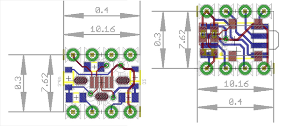
[Atom] is using a few interesting components in this build. The USB connector is a surface mount vertical part, making the USB cord stick out the top of this uC board. The reset button is extremely small as well, sticking out of the interior layer of the PCB sandwich.

[AtomSoft] has the project up on OSH Park ($1.55 for three. How cool is that?), and we assume he’ll be selling the official World’s Smallest Arduino-compatible board at Tindie in time.


Filed under: Arduino Hacks, ATtiny Hacks
Jan
13

Software Half Duplex UART for AVRs

arduino hacks, attiny, ATtiny Hacks, half duplex, software uart, uart Comments Off on Software Half Duplex UART for AVRs 

One Wire Serial

If you have worked with very low cost microcontroller in the past, such as the ATtiny series from AVR, you’ve probably been stuck without a UART peripheral. The usual answer to this problem is to implement the UART in software. It’s not fast, but it works.

Lets say you’re even more limited on resources, and only have a single pin for UART. [Ralph] created a software library and a small circuit that enables half duplex UART using only one pin. With the above circuit, and a 62 byte Arduino compatible library, you can add UART to the tiniest of ATtinys.

In this circuit, the Tx/Rx pin is on the AVR, and the Tx and Rx pins are another device. The circuit relies on the idle state of UART being a logic high signal. When the Tx pin is idle, the transistor stays on. This allows the Tx/Rx pin to pull Rx low when the AVR sends a 0. When the Tx pin sends a 0, the Tx/Rx pin gets pulled low through the diode.

It’s a clever hack, and could definitely help add communication to your next tiny project.


Filed under: Arduino Hacks, ATtiny Hacks


  • Newsletter

    Sign up for the PlanetArduino Newsletter, which delivers the most popular articles via e-mail to your inbox every week. Just fill in the information below and submit.

  • Like Us on Facebook