The Adafruit LTC4316 I2C Address Translator does on the fly I2C address translation. There’s an ‘input I2C’ half, and an ‘output I2C’ half. And any devices on the ‘output’ half will automatically have their addresses translated from the input half. Specifically, each device will have bit A6 flipped (most-significant-bit of the address) and then bits A4 and A5 can also be flipped or kept the same, with the two DIP switches on board. To determine the translated address, we use XOR bitwise math.
The Adafruit LTC4316 I2C Address Translator guide has everything you need to get started with using this breakout. There’s pages for overview, pinouts, CircuitPython, Arduino and resources for download.
Waveshare RP2040-GEEK is a development board that looks like a USB flash drive but is based on a Raspberry Pi RP2040 microcontroller with a 1.14-inch 65K color LCD and some expansion ports all housed in a white plastic case. The device comes with a 4MB flash to store the firmware, a microSD card slot for data storage, a BOOT button to enter bootloader mode, two 3-pin connectors for UART and SWD debug, and a 4-pin I2C port. Waveshare RP2040-GEEK specifications: MCU – Raspberry Pi RP2040 dual-core Arm Cortex-M0+ microcontroller clocked up to 133 MHz with 264 kB SRAM Storage – 4MB flash (W25Q32JVSSIQ) and microSD card slot Display – 1.14-inch 240×135 pixel 65K color IPS LCD display USB – 1x USB Type-A female port for power and programming Debugging – 3-pin SWD port for connecting a target board; the standard CMSIS-DAP interface can be used to debug most Arm-based microcontrollers; [...]
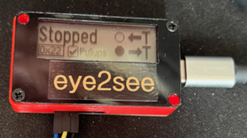
For as popular as the Arduino platform is, it’s not without its problems. Among those is the fact that most practical debugging is often done by placing various print statements throughout the code and watching for them in the serial monitor. There’s not really a great way of placing breakpoints or stepping through code, either. But this project, known as eye2see, hopes to change that by using the i2c bus found in most Arduinos to provide a more robust set of debugging tools.
The eye2see software is set up to run on an Arduino or other compatible microcontroller, called the “probe”, which is connected to the i2c bus on another Arduino whose code needs to be debugged. Code running on this Arduino, which is part of the eye2see library, allows it to send debugging information to the eye2see probe. With a screen, the probe can act as a much more powerful debugger than would otherwise typically be available, being able to keep track of variables in the main program, setting up breakpoints, and outputting various messages on its screen.
The tool is not without its downsides, though. The library that needs to run on the host Arduino slows down the original program significantly. But for more complex programs, the tradeoff with powerful debugging tools may be worth it until these pieces of code can be removed and the program allowed to run unencumbered. If you’d like to skip needing to use a second Arduino, we’ve seen some other tools available for debugging Arduino code that can run straight from a connected PC instead.
Controlling your computer with a wave of the hand seems like something from science fiction, and for good reason. From Minority Report to Iron Man, we’ve seen plenty of famous actors controlling their high-tech computer systems by wildly gesticulating in the air. Meanwhile, we’re all stuck using keyboards and mice like a bunch of chumps.
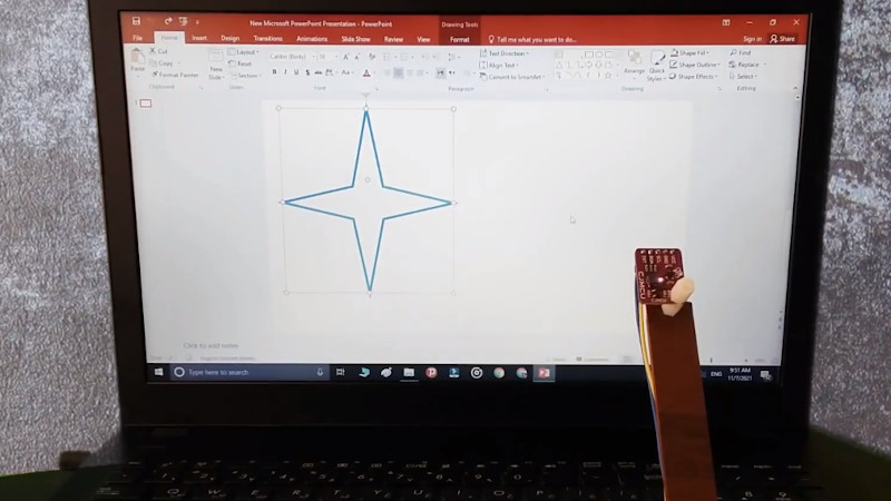
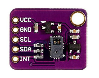
But it doesn’t have to be that way. As [Norbert Zare] demonstrates in his latest project, you can actually achieve some fairly impressive gesture control on your computer using a $10 USD PAJ7620U2 sensor. Well not just the sensor, of course. You need some way to convert the output from the I2C-enabled sensor into something your computer will understand, which is where the microcontroller comes in.
Looking through the provided source code, you can see just how easy it is to talk to the PAJ7620U2. With nothing more exotic than a switch case statement, [Norbert] is able to pick up on the gesture flags coming from the sensor. From there, it’s just a matter of using the Arduino Keyboard library to fire off the appropriate keycodes. If you’re looking to recreate this we’d go with a microcontroller that supports native USB, but technically this could be done on pretty much any Arduino. In fact, in this case he’s actually using the ATtiny85-based Digispark.
This actually isn’t the first time we’ve seen somebody use a similar sensor to pull off low-cost gesture control, but so far, none of these projects have really taken off. It seems like it works well enough in the video after the break, but looks can be deceiving. Have any Hackaday readers actually tried to use one of these modules for their day-to-day futuristic computing?
In an age of streaming media it’s easy to forget the audio CD, but they still remain as a physical format from the days when the “Play” button was not yet the “Pay” button. A CD player may no longer be the prized possession it once was, but it’s still possible to dabble in the world of 120 mm polycarbonate discs if you have a fancy for it. It’s something [Daniel1111] has done with his Arduino CD player, which uses the little microcontroller board to control a CD-ROM drive via its IDE bus.
The project draws heavily from the work of previous experimenters, notably ATAPIDUINO, but it extends them by taking its audio from the drive’s S/PDIF output. A port expander drives the IDE interface, while a Cirrus Logic WM8805 S/PDIF transceiver handles the digital audio and converts it to an I2S stream. That in turn is fed to a Texas Instruments PCM5102 DAC, which provides a line-level audio output. All the code and schematic can be found in a GitHub repository.
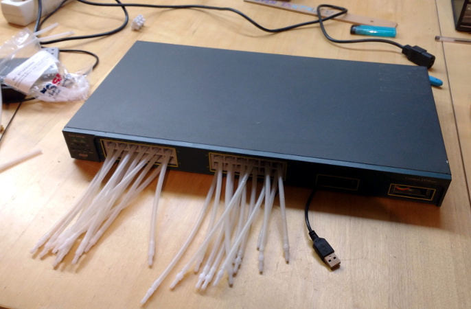
You’d be hard pressed to find an IT back office that doesn’t have a few Cisco routers or switches laying around and collecting dust. We’d even bet there are a decent number of people reading this post right now that have a stack of them within arm’s reach. They’re the kind of thing most of us have no practical application for, but we still can’t bear to throw away. But it looks like [Sven Tantau] has found an ideal middle ground: rather than junk his Cisco Catalyst switches, he turned them into automatic bartenders.
Inspired by all those perfect little square openings on the front, [Sven] loaded each switch with a whopping 24 peristaltic pumps, one for each Ethernet port. To fit all his plumbing inside, the switches were naturally gutted to the point of being hollow shells of their former selves, although he does mention that their original power supplies proved useful for keeping two dozen power-hungry motors well fed.
The motors are connected to banks of relays, which in turn are thrown by an ESP32 and an Arduino Nano. [Sven] explains that he wasn’t sure if the ESP32 could fire off the relays with its 3 V output, so he decided to just use an Arduino which he already knew could handle the task. The two microcontrollers work in conjunction, with a web interface on the ESP32 ultimately sending I2C commands to the Arduino when it’s time to get the pumps spinning.
A Raspberry Pi Zero (W) and Arduino are very different animals, the prior has processing power and connectivity while the latter has some analog to digital converters (ADCs) and nearly real-time reactions. You can connect them to one another with a USB cable and for many projects that will happily wed the two. Beyond that, we can interface this odd couple entirely through serial, SPI, I2C, and logic-level signaling. How? Through a device by [cburgess] that is being called an Arduino shield that supports a Pi0 (W). Maybe it is a cape which interfaces with Arduino. The distinction may be moot since each board has a familiar footprint and both of them are found here.
Depending on how they are set up and programmed, one can take control over the other, or they could happily do their own thing and just exchange a little information. This board is like a marriage counselor between a Raspberry Pi and an Arduino. It provides the level-shifting so they don’t blow each other up and libraries so they can speak nicely to one another. If you want to dig a bit deeper into this one, design files and code examples are on available.
In the era of touch screens and capacitive buttons, we’d be lying if we said we didn’t have the occasional pang of nostalgia for the good old days when interfacing with devices had a bit more heft to it. The physical clunk and snap of switches never seems to get old, and while you can always pick up a mechanical keyboard for your computer if you want to hear that beautiful staccato sound while firing off your angry Tweets, there’s a definite dearth of mechanical interface devices otherwise.
[Jeremy Cook] decided to take matters into his own hands (literally and figuratively) by designing his own multipurpose USB rotary input device. It’s not a replacement for the mouse or keyboard, but a third pillar of the desktop which offers a unique way of controlling software. It’s naturally suited to controlling things like volume or any other variable which would benefit from some fine tuning, but as demonstrated in the video after the break even has some gaming applications. No doubt the good readers of Hackaday could think of even more potential applications for a gadget like this.
The device is built around the diminutive Arduino-compatible PICO board by MellBell, which features a ATmega32u4 and native USB. This allowed him to very rapidly spin up a USB Human Interface Device (HID) with minimal headaches, all he had to do was hang his buttons and rotary encoder on the PICO’s digital pins. To that end, he [Jeremy] used the fantastic I2C rotary encoder designed by [fattore.saimon], which readers may remember as a finalist in the Open Hardware Design Challenge phase of the 2018 Hackaday Prize. He also added a NeoPixel ring around the encoder to use for some visual feedback and because, well, it just looks cool.
Since all of the core components are digital, there’s not a whole lot required in the way of wiring or passive components. This let [Jeremy] put the whole thing together on a piece of perfboard, freeing him up to spend time designing the 3D printed enclosure complete with translucent lid so he can see the NeoPixel blinkenlights. He got the tolerances tight enough that the whole device can be neatly press-fit together, and even thought to add holes in the bottom of the case so he could push the perfboard back out if he needed to down the line.
[Jeremy] spends a good chunk of the video going over the software setup and development of the firmware, and details some of the nuances he had to wrap his head around when working with the I2C encoder. He also explains the math involved in getting his encoder to emulate a mouse cursor moving in a circle, which he thinks could be useful when emulating games that originally used an encoder such as Tempest or Pong.
Amazon might not be happy about it, but at least part of the success of their Fire TV Stick was due to the large hacking and modification scene that cropped up around the Android-powered device. A quick search on YouTube for “Fire Stick Hack” will bring up a seemingly endless array of videos, some with millions of views, which will show viewers how to install unofficial software on the little media dongle. Now it looks like their latest media device, the Fire TV Cube, is starting to attract the same kind of attention.
The team at [Exploitee.rs] has recently taken the wraps off their research which shows the new Fire TV Cube can be rooted with nothing more than an Arduino and an HDMI cable you’re willing to cut apart. Of course, it’s a bit more complicated than just that, but between the video they’ve provided and their WiKi, it looks like all the information is out there for anyone who wants to crack open their own Cube. Just don’t be surprised if it puts you on the Amazon Naughty List.
The process starts by putting the device’s Amlogic S905Z into Device Firmware Upgrade (DFU) mode, which is done by sending the string “boot@USB” to the board over the HDMI port’s I2C interface. That’s where the HDMI cable comes in: you can cut into one and wire it right up to your Arduino and run the sketch [Exploitee.rs] has provided to send the appropriate command. Of course, if you want to get fancy, you could use an HDMI breakout board instead.
With the board in DFU mode in you gain read and write access to the device’s eMMC flash, but that doesn’t exactly get you in because there’s still secure boot to contend with. But as these things tend to go, the team was able to identify a second exploit which could be used in conjunction with DFU mode to trick the device into disabling signature verification. Now with the ability to run unsigned code on the Fire TV Cube, [Exploitee.rs] implemented fastboot to make it easier to flash their custom rooted firmware images to the hardware.
As with the Fire TV Stick before it, make sure you understand the risks involved when you switch off a device’s security features. They’re often there to protect the end user as much as the manufacturer.
Planet Arduino is, or at the moment is wishing to become, an aggregation of public weblogs from around the world written by people who develop, play, think on Arduino platform and his son. The opinions expressed in those weblogs and hence this aggregation are those of the original authors. Entries on this page are owned by their authors. We do not edit, endorse or vouch for the contents of individual posts. For more information about Arduino please visit www.arduino.cc
You are currently browsing the archives for the i2c category.