Posts | Comments

Planet Arduino

Archive for the ‘iic’ Category

Introduction

Some of you may be using an Arduino Leonardo board, taking advantage of the newer ATmega32U4 microcontroller for various reasons. And rightly so – there’s the extra analogue I/O, virtual USB and the microUSB socket so you can use your phone charger cable. However with the new microcontroller comes a few changes to the board pinouts – I2C and SPI have moved. So if you have a nice Ethernet shield or something using I2C – you’re basically out of luck… until now. The problem has been solved nicely by the team at GorillaBuilderz have created their LeoShield:

Use

You simply place it on the Leonardo, and then the older legacy shield on top. The LeoShield redirects the I2C pins back to A4 and A5, and also sends the SPI lines back to D11~D13. For example, our Ethernet shield:

The ICSP pins are also extended from the Leonardo to the LeoShield, for example:

however when inserting the LeoShield into your Leonardo, take care lining up all the pins before pushing the shield down. There is also the large prototyping area which has 5V , 3.3V and GND rails across the full width for convenience. The sticker on the rear of the shield is to insulate against any large items that may come in contact from the host board, however you can peel it off to realise the complete prototyping space.

Conclusion

It’s simple and it works – so if you need to use an older Arduino shield with a Leonardo the choice is simple – get yourself a Leoshield.

Disclaimer - The Leoshield was a review product received from GorillaBuilderz.

Thanks for reading tronixstuff.com. I’ve got some new tutorials coming up very soon, and a lot of existing posts are curently being updated – so follow things on twitterGoogle+, subscribe  for email updates or RSS using the links on the right-hand column. And join our friendly Google Group – dedicated to the projects and related items on this website. Sign up – it’s free, helpful to each other –  and we can all learn


Introduction

Some of you may be using an Arduino Leonardo board, taking advantage of the newer ATmega32U4 microcontroller for various reasons. And rightly so – there’s the extra analogue I/O, virtual USB and the microUSB socket so you can use your phone charger cable. However with the new microcontroller comes a few changes to the board pinouts – I2C and SPI have moved. So if you have a nice Ethernet shield or something using I2C – you’re basically out of luck… until now. The problem has been solved nicely by the team at GorillaBuilderz have created their LeoShield:

Use

You simply place it on the Leonardo, and then the older legacy shield on top. The LeoShield redirects the I2C pins back to A4 and A5, and also sends the SPI lines back to D11~D13. For example, our Ethernet shield:

The ICSP pins are also extended from the Leonardo to the LeoShield, for example:

however when inserting the LeoShield into your Leonardo, take care lining up all the pins before pushing the shield down. There is also the large prototyping area which has 5V , 3.3V and GND rails across the full width for convenience. The sticker on the rear of the shield is to insulate against any large items that may come in contact from the host board, however you can peel it off to realise the complete prototyping space.

Conclusion

It’s simple and it works – so if you need to use an older Arduino shield with a Leonardo the choice is simple – get yourself a Leoshield.

leoleoshieldsmall

Disclaimer - The Leoshield was a review product received from GorillaBuilderz.

Thanks for reading tronixstuff.com. I’ve got some new tutorials coming up very soon, and a lot of existing posts are curently being updated – so follow things on twitterGoogle+, subscribe  for email updates or RSS using the links on the right-hand column. And join our friendly Google Group – dedicated to the projects and related items on this website. Sign up – it’s free, helpful to each other –  and we can all learn

The post Review: GorillaBuilderz LeoShield appeared first on tronixstuff.

This is part of a series titled “Getting Started with Arduino!” by John Boxall – A tutorial on the Arduino microcontrollers, to be read with the book “Getting Started with Arduino” (Massimo Banzi).

The first chapter is here.

Welcome back fellow arduidans!

This week we will continue to examine the features of the DS1307 real time clock, receive user input in a new way, use that input to control some physical movement, then build a strange analogue clock. So let’s go!

Recall from chapter seven, that the DS1307 is also has an inbuilt square wave generator, which can operate at a frequency of 1Hz. This is an ideal driver for a “seconds” indicator LED. To activate this you only need to send the hexidecimal value 0×10 after setting the date and time parameters when setting the time. Note this in line 70 of the solution for exercise 7.1. This also means you can create 1Hz pulses for timing purposes, an over-engineered blinking LED, or even an old-school countdown timer in conjunction with some CMOS 4017 ICs.

For now, let’s add a “seconds” LED to our clock from exercise 7.1. The hardware is very simple, just connect a 560 ohm resistor to pin 7 of our DS1307, thence to a normal LED of your choice, thence to ground. Here is the result:

Not that exciting, but it is nice to have a bit more “blinkiness”.

Finally, there is also a need to work with 12-hour time. From the DS1307 data sheet we can see that it can be programmed to operate in this way, however it is easier to just work in 24-hour time, then use mathematics to convert the display to 12-hour time if necessary. The only hardware modification required is the addition of an LED (for example) to indicate whether it is AM or PM. In my example the LED indicates that it is AM.

Exercise 8.1

So now that is your task, convert the results of exercise 7.1 to display 12-hour time, using an LED to indicate AM or PM (or two LEDs, etc…)

Here is my result in video form:

and the sketch: exercise8.1.pdf.

OK then, that’s enough about time for a while. Let’s learn about another way of accepting user input…

Your computer!

Previously we have used functions like Serial.write() and Serial.print() to display data on the serial monitor box in the Arduino IDE. However, we can also use the serial monitor box to give our sketch data. At first this may seem rather pointless, as you would not use an Arduino just to do some maths for you, etc. However – if you are controlling some physical hardware, you now have a very simple way to feed it values, control movements, and so on. So let’s see how this works.

The first thing to know is that the serial input has one of two sources, either the USB port (so we can use the serial monitor in the Arduino IDE) or the serial in/out pins on our Arduino board. These are digital pins 0 and 1. You cannot use these pins for non-serial I/O functions in the same sketch. If you are using an Arduino Mega or compatible board (lucky you) the pins are different, please see here.  For this chapter, we will use the USB port for our demonstrations.

Next, data is accepted in bytes (remember – 8 bits make a byte!). This is good, as a character (e.g. the letter A) is one byte. Our serial  input has a receiving buffer of 128 bytes. This means a project can receive up to 128 bytes whilst executing a portion of a sketch that does not wait for input. Then when the sketch is ready, it can allow the data to serially flow in from the buffer. You can also flush out the buffer, ready for more input. Just like a … well let’s keep it clean.

Ok, let’s have a look. Here is a sketch that accepts user input from your computer keyboard via the serial monitor box. So once you upload the sketch, open the serial monitor box and type something, then press return or enter. Load this sketch, example 8.1.pdf. Here is a quick video clip of it in operation:

Notice in the line Serial.print(character, BYTE); that we force the display to byte, this is to show the value as the matching ASCII character; otherwise it would return the ASCII value of the character instead. For the young ones out there, please read this for an explanation of the ASCII table.

So now we can have something we already know displayed in front of us. Not so useful. However, what would be useful is converting the keyboard input into values that our Arduino can work with.

Consider this example – example 8.2.pdf. It accepts an integer from the input of serial monitor box, converts it to a number you can use mathematically, and performs an operation on that number. Here is a shot of it in action:

If you are unsure about how it works, follow the sketch using a pen and paper, that is write down a sample number for input, then run through the sketch manually, doing the computations yourself. I often find doing so is a good way of deciphering a complex sketch. Once you have completed that, it is time for…

Exercise 8.2

Create a sketch that accept an angle between 0 and 180, and a time in seconds between 0 and (say) 60. Then it will rotate a servo to that angle and hold it there for the duration, then return it to 0 degrees. For a refresher on servo operation, visit chapter three before you start.

Here is a video clip of my interpretation at work:

and the example solution sketch: exercise 8.2.pdf

So now you have the ability to generate user input with a normal keyboard and a PC. In the future we will examine doing so without the need for a personal computer…

Finally, let’s have some fun by combining two projects from the past into one new exercise.

Exercise 8.3

Create an analogue clock using two servos, in a similar method to our analogue thermometer from chapter three. The user will set the time (hours and minutes) using the serial monitor box.

Here is a photo of my example. I spared no expense on this one…

And of course a video demonstration. First we see the clock being set to 12:59, then the hands moving into position, finally the transition from 12:59 to 1:00.

If you had more servos and some earplugs, a giant day/date/clock display could be made… If you like different clocks, have a look at these kits.

Nevertheless, we have had another hopefully interesting and educational lecture. Or at least had a laugh

Another week over. I apologise for this chapter being a little shorter than usual, unfortunately we have some sickness in the family. However, as usual I’m already excited about writing the next instalment… Congratulations to all those who took part and built something useful! Please subscribe (see the top right of this page) to receive notifications of new articles. High resolution photos are available from flickr.

If you have any questions at all please leave a comment (below). We also have a Google Group dedicated to the projects and related items on the website – please sign up, it’s free and we can all learn something -

If you would like to showcase your work from this article, email a picture or a link to john at tronixstuff dot com.

You might even win a prize. Don’t forget to check out the range of gear at Little Bird Electronics!

So have fun, stay safe and see you soon for our next instalment!


This is part of a series titled “Getting Started with Arduino!” – A tutorial on the Arduino microcontrollers, to be read with the book “Getting Started with Arduino” (Massimo Banzi).

The first chapter is here.

Welcome back fellow arduidans!

This week is going to focus around the concept of real time, and how we can work with time to our advantage. (Perhaps working with time to our disadvantage is an oxymoron…) Once we have the ability to use time in our sketches, a whole new world of ideas and projects become possible. From a simple alarm clock, to complex timing automation systems, it can all be done with our Arduino and some brainpower. There is no time to waste, so let’s go!

First of all, there are a few mathematical and variable-type concepts to grasp in order to be able to understand the sketch requirements. It is a bit dry, but I will try and minimise it.

The first of these is binary-coded decimal.

Can you recall from chapter four how binary numbers worked? If not, have a look then come back. Binary coded decimal (or BCD) numbers are similar, but different… each digit is stored in a nibble of data. Remember when working with the 74HC595 shift registers, we sent bytes of data – a nibble is half of a byte. For example:

Below is a short clip of BCD in action – counting from 0 to 9 using LEDs:

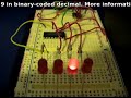
However, remember each digit is one nibble, so to express larger numbers, you need more bits. For example, 12 would be 0001 0010; 256 is 0010 0101 0110, etc. Note that two BCD digits make up a byte. For example, the number 56 in BCD is 0101 0110,  which is 2 x 4 bits = 1 byte.

Next, we will need to work with variables that are bytes. Like any other variable, they can be declared easily, for example:

byte seconds = B11111;

B11111 is 31 in base 10, (that is, 2^4+2^3+2^2+2^1+2^0     or    16+8+4+2+1)

However, you can equate an integer into a byte variable. Here is a small sketch demonstrating this: example7.1.pdf

And the result:

If you printed off the results of the sketch in example 7.1, it would make a good cheat sheet for the Binary Quiz program in Chapter Five.

Anyhow, moving forward we now take a look at hexadecimal numbers. ‘Hex’ numbers are base-16, in that 16 digits/characters are used to represent numbers. Can you detect a pattern with the base-x numbers? Binary numbers are base-2, as they use 0 and 1; decimal numbers are base-10, as they use 0 to 9 – and hexadecimal numbers use 0 to 9 then A to F. Run the following sketch to see how they compare with binary and decimal: Example 7.2.pdf

Below is a screenshot of the result: the left column is hexadecimal, the centre binary, and the right decimal.

Unfortunately the IC we use for timing uses BCD, so we need to be able to convert to and from BCD to make sense of the timing data.

So now we have an understanding of BCD, binary, base-10 decimal, bytes, hexadecimal and nibbles. What a mouthful that was!

Coffee break.

Before we head back to timing, let’s look at a new function: switch… case. Say you needed to examine a variable, and make a decision based on the value of that variable, but there were more than two possible options. You could always use multiple if…then…else if functions, but that can be hard on the eyes. That is where switch… case comes in. It is quite self-explanatory, look at this example:

switch (zz) {
case 10:
//do something when variable zz equals 10
break;
case 20:
//do something when variable zz equals 20
break;
case 30:
// do something when variable equals 30
break;
default:
// if nothing else matches, do the default
// default is optional
}

OK, we’re back. It would seem that this chapter is all numbers and what not, but we are scaffolding our learning to be able to work with an integrated circuit that deals with the time for us. There is one last thing to look at then we can get on with timing things. And that thing is…

The I2C bus.

(There are two ways one could explain this, the simple way, and the detailed way. As this is “Getting Started with Arduino”, I will use the simple method. If you would like more detailed technical information, please read this document: NXP I2C Bus.pdf, or read the detailed website by NXP here)

The I2C bus (also known as “two wire interface”) is the name of a type of interface between devices (integrated circuits) that allows them to communicate, control and share data with each other. (It was invented by Philips in the late 1970s. [Philips spun off their semiconductor division into NXP]).  This interchange of data occurs serially, using only  two wires (ergo two wire interface), one called SDA (serial data) and the other SCL (serial clock).

I2C bus – image from NXP documentation

A device can be a master, or a slave. In our situation, the Arduino is the master, and our time chip is the slave. Each chip on the bus has their own unique “address”, just like your home address, but in binary or in hexadecimal. You use the address in your sketch before communicating with the desired device on the I2C bus. There are many different types of devices that work with the I2C bus, from lighting controllers, analogue<> digital converters, LED drivers, the list is quite large. But the chip of interest to us, is the:

Maxim DS1307 Serial I2C real-time clock. Let’s have a look:

This amazing little chip, with only a few external components, can keep track of the time in 12-and 24-hour formats, day of week, calendar day, month and year, leap years, and the number of days in a month. Interestingly, it can also generate a square wave at 1Hz, 4kHz, 8kHz, or 32 kHz. For further technical information, here is the DS1307 data sheet.pdf. Note – the DS1307 does not work below 0 degrees Celsius/32 degrees Fahrenheit, if you need to go below freezing, use a DS1307N.

Using the DS1307 with our Arduino board is quite simple, either you can purchase a board with the chip and external circuitry ready to use, or make the circuit yourself. If you are going to do it yourself, here is the circuit diagram for you to follow: (click on image to enlarge)


The 3V battery is for backup purposes, a good example to use would be a CR2032 coin cell – however any 3V, long-life source should be fine. If you purchase a DS1307 board, check the battery voltage before using it…. my board kept forgetting the time, until I realised it shipped with a flat battery. The backup battery will not allow the chip to communicate when Vcc has dropped, it only allows the chip to keep time so it is accurate when the supply voltage is restored. Fair enough. The crystal is 32.768 kHz, and easily available. The capacitor is just a standard 0.1uF ceramic.

Now to the software, or working with the DS1307 in our sketches. To enable the I2C bus on Arduino there is the wire library which contains the functions required to communicate with devices connected to our I2C bus. The Arduino (Duemilanove) pins to use are analogue 4 (data) and analogue 5 (clock). If you are using a mega, they are 20 (data) and 21 (clock). There are only three things that we need to accomplish: initially setting the time data to the chip; reading the time data back from the chip; and enabling that 1Hz square-wave function (very useful – if you were making an LED clock, you could have a nice blinking LED).

First of all, we need to know the I2C address for our DS1307. It is 0×68 in hexadecimal. Addresses are unique to the device type, not each individual device of the same type.

Next, the DS1307 accepts or returns the timing data in a specific order…

  • seconds (always set seconds to zero, otherwise the oscillator in the DS1307 will stay off)
  • minutes
  • hours
  • day of week (You can set this number to any value between 1 and 7, e.g. 1 is Sunday, then 2 is Monday…)
  • day of month
  • month
  • year
  • control register (optional – used to control the square-wave function frequency and logic level)

… but it only accepts and returns this data in BCD. So – we’re going to need some functions to convert decimal numbers to BCD and vice-versa (unless you want to make a BCD clock …)

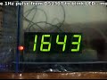
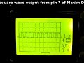
However, once again in the interests of trying to keep this simple, I will present you with a boilerplate sketch, with which you can copy and paste the code into your own creations. Please examine this file: example 7.3.pdf. Note that this sketch also activates the 1Hz square wave, available on pin 7. Below is a quick video of this square wave on my little oscilloscope:

This week we will look at only using 24-hour time; in the near future we will examine how to use 12-hour (AM/PM) time with the DS1307.

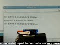
Here is a screen capture of the serial output box:

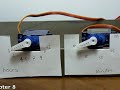
Now that you have the ability to send this time data to the serial output box, you can send it to other devices. For example, let’s make a simple LCD clock. It is very easy to modify our example 7.3 sketch, the only thing to take into account is the available space on the LCD module. To save time I am using the Electronic Brick kit to assemble this example. Below is a short clip of our LCD clock operating:

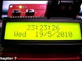
and here is the sketch: example 7.4.pdf. After seeing that clock fire up and work correctly, I felt really great – I hope you did too. Now let’s head back in time, to when digital clocks were all the rage…
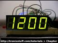
Exercise 7.1

Using our Arduino, DS1307 clock chip, and the exact hardware from exercise 6.2 (except for the variable resistor, no need for that) – make a nice simple digital clock. It will only need to show the hours and minutes, unless you wish to add more display hardware. Have fun!

Here is my result, in video form:

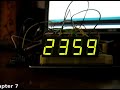
and the sketch: exercise 7.1.pdf. Just an interesting note – after you upload your sketch to set the time; comment out the line to set the time, then upload the sketch a second time. Otherwise every time your clock loses power and reboots, it will start from the time defined in the sketch!

Another week over! And once again, I’m already excited about writing the next instalment… Congratulations to all those who took part and built something useful! Please subscribe (see the top right of this page) to receive notifications of new articles. High resolution photos are available from flickr.

If you have any questions at all please leave a comment (below). We also have a Google Group dedicated to the projects and related items on the website – please sign up, it’s free and we can all learn something -

If you would like to showcase your work from this article, email a picture or a link to john at tronixstuff dot com.

You might even win a prize. Don’t forget to check out the range of gear at Little Bird Electronics!

So have fun, stay safe and see you soon for our next instalment!


  • Newsletter

    Sign up for the PlanetArduino Newsletter, which delivers the most popular articles via e-mail to your inbox every week. Just fill in the information below and submit.

  • Like Us on Facebook