Kevin from the Simple DIY Electronic Music Projects blog describes a PCB version of the Arduino EEPROM Reader/Writer as described here but with slight adjustments to support reading of 27Cxxx style ROMs often found in vintage equipment.
This is essentially the circuit from Ben Eater’s github repository, but there are a couple of configuration options for some of the connections to the (E)EPROM to support 27Cxxx, 28Cxxx (and probably 29Cxxx, which have the same pin-out as the 28Cxxx) style ROMs for reading.
Microcontrollers tend to consume other kinds of electronics. A project you might once have done with a 555 now probably has a cheap microcontroller in it. Music synthesizers? RC controllers? Most likely, all microcontroller-based now. We always thought RF electronics would be immune to that, but the last decade or two has proven us wrong. Software-defined radio or SDR means you get the RF signal to digital as soon as possible and do everything else in software. If you want an introduction to SDR, Elektor now has an inexpensive RF shield for the Arduino. The Si5351-based board uses that oscillator IC to shift RF signals down to audio frequencies and then makes it available to the PC to do more processing.
The board is available alone or as part of a kit that includes a book. There’s also a series of Elektor articles about it. There’s also a review video from Elektor about the board in the video, below.
We peeked at the schematic and the shield is more for letting the Arduino control the radio by changing the oscillator frequency rather than performing the SDR functions. The IQ signals appear on the PC’s soundcard via a microphone or line-in jack, and don’t really route to the Arduino.
That’s a shame because some of the 32-bit Arduinos might be able to do some interesting things with the right hardware. Plus there are many capable CPU and FPGA boards that have Arduino shield-compatible layouts. That could have led to some interesting possibilities.
Then again, having a programmable signal source on the Arduino isn’t a bad thing and compared to the older version of the board, the new board offers easier breakout for the oscillator signals.
If you want to learn more about how SDR works, try starting with spreadsheets. However, if you want to graduate to something more practical, try our series on GNU Radio.
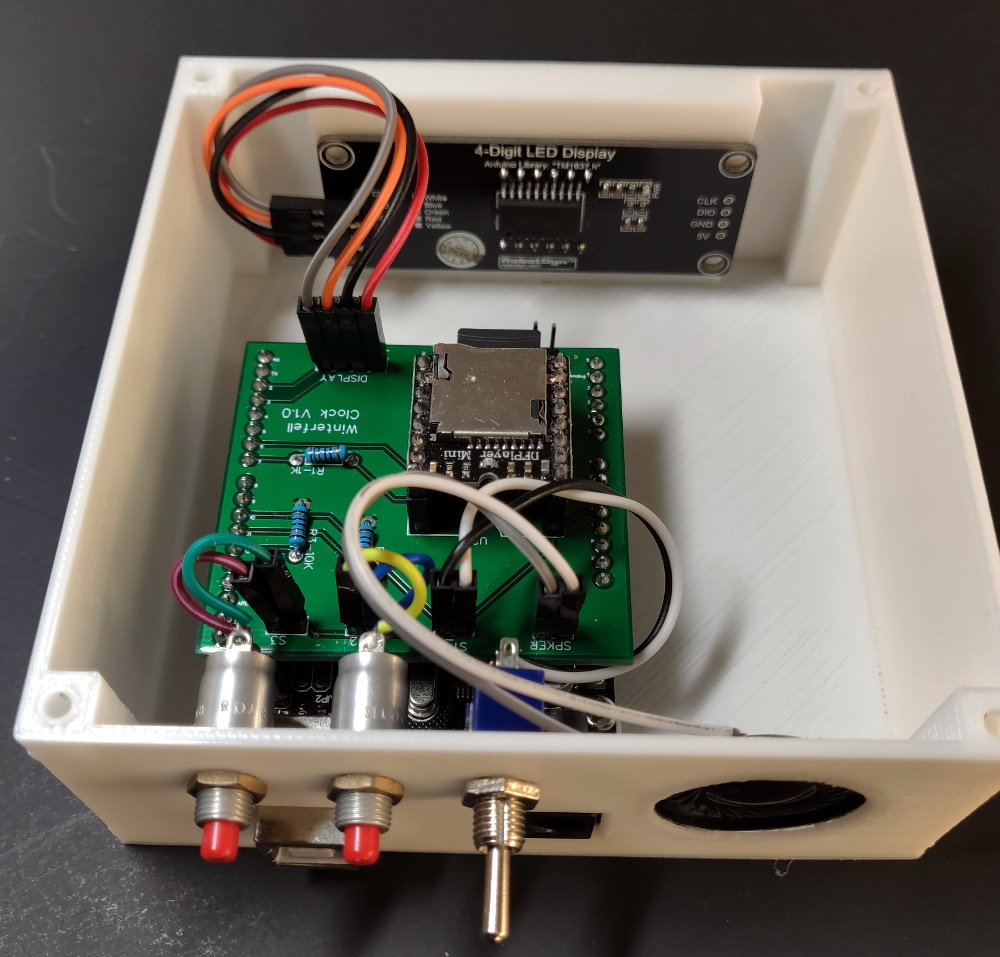
For Game of Thrones fans, it’s an awkward time. The show has ended its run on HBO (not without a certain level of controversy), the planned prequel is still years away, and who knows when George R. R. Martin will actually get around to writing the final books in the series. Fans have no choice but to entertain themselves while waiting for further tales of adventure from Westeros, which is how we get things like this motorized clock from [Techarge].
Inspired by the now iconic opening sequence from the HBO series, elements of the 3D printed model spin around while the theme song is played courtesy of a DFPlayer Mini MP3 player module and small 2 watt speaker. The audio hardware, motor, and four digit LED display module in the front are all connected to an Arduino with a custom PCB shield, giving the inside of the clock a very clean and professional appearance.
Around the back side [Techarge] has two small push buttons to set the hour and minutes, and a large toggle to control the music and movement. As of right now it needs to be switched on and off manually, but a future enhancement could see it kick on hourly. We’d also like to see an RTC module added to the PCB, or better yet, switch over to the ESP8266 and just pull the time down from NTP.
Who knows? By the time you’ve built one of these clocks for yourself, and the hand-made Iron Throne phone charger stand to go with it, maybe ol’ George will have slipped out a new book. But don’t count on it.
In this tutorial we look at how to use the neat LED Real Time Clock Temperature Sensor Shield for Arduino from PMD Way. That’s a bit of a mouthful, however the shield does offer the following:
four digit, seven-segment LED display
DS1307 real-time clock IC
three buttons
four LEDs
a active buzzer
a light-dependent resistor (LDR)
and a thermistor for measuring ambient temperature
The shield also arrives fully-assembled , so you can just plug it into your Arduino Uno or compatible board. Neat, beginners will love that. So let’s get started, by showing how each function can be used – then some example projects. In no particular order…
The buzzer
A high-pitched active buzzer is connected to digital pin D6 – which can be turned on and off with a simple digitalWrite() function. So let’s do that now, for example:
voidsetup(){// buzzer on digital pin 6pinMode(6,OUTPUT);}// the loop function runs over and over again forevervoidloop(){digitalWrite(6,HIGH);// turn the buzzer on (HIGH is the voltage level)delay(1000);// wait for a seconddigitalWrite(6,LOW);// turn the buzzer off by making the voltage LOWdelay(1000);// wait for a second}
If there is a white sticker over your buzzer, remove it before uploading the sketch. Now for a quick video demonstration. Turn down your volume before playback.
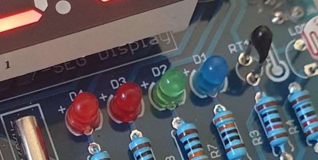
The LEDs
Our shield has four LEDs, as shown below:
They’re labelled D1 through to D4, with D1 on the right-hand side. They are wired to digital outputs D2, D3, D4 and D5 respectively. Again, they can be used with digitalWrite() – so let’s do that now with a quick demonstration of some blinky goodness. Our sketch turns the LEDs on and off in sequential order. You can change the delay by altering the variable x:
voidsetup(){// initialize digital pin LED_BUILTIN as an output.pinMode(2,OUTPUT);// LED 1pinMode(3,OUTPUT);// LED 2pinMode(4,OUTPUT);// LED 3pinMode(5,OUTPUT);// LED 4}intx=200;voidloop(){digitalWrite(2,HIGH);// turn on LED1delay(x);digitalWrite(2,LOW);// turn off LED1. Process repeats for the other three LEDsdigitalWrite(3,HIGH);delay(x);digitalWrite(3,LOW);digitalWrite(4,HIGH);delay(x);digitalWrite(4,LOW);digitalWrite(5,HIGH);delay(x);digitalWrite(5,LOW);}
And in action:
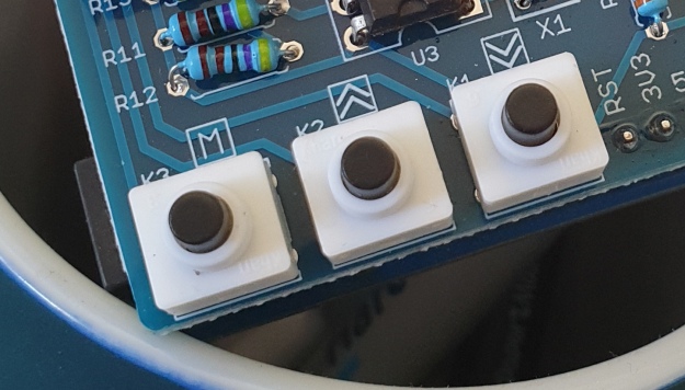
The Buttons
It is now time to pay attention to the three large buttons on the bottom-left of the shield. They look imposing however are just normal buttons, and from right-to-left are connected to digital pins D9, D10 and D11:
They are, however, wired without external pull-up or pull-down resistors so when initialising them in your Arduino sketch you need to activate the digital input’s internal pull-up resistor inside the microcontroller using:
pinMode(pin, INPUT_PULLUP);
Due to this, buttons are by default HIGH when not pressed. So when you press a button, they return LOW. The following sketch demonstrates the use of the buttons by lighting LEDs when pressed:
voidsetup(){// initalise digital pins for LEDs as outputspinMode(2,OUTPUT);// LED 1pinMode(3,OUTPUT);// LED 2pinMode(4,OUTPUT);// LED 3// initalise digital pins for buttons as inputs// and initialise internal pullupspinMode(9,INPUT_PULLUP);// button K1pinMode(10,INPUT_PULLUP);// button K2pinMode(11,INPUT_PULLUP);// button K3}voidloop(){if(digitalRead(9)==LOW){digitalWrite(2,HIGH);delay(10);digitalWrite(2,LOW);}if(digitalRead(10)==LOW){digitalWrite(3,HIGH);delay(10);digitalWrite(3,LOW);}if(digitalRead(11)==LOW){digitalWrite(4,HIGH);delay(10);digitalWrite(4,LOW);}}
You can see these in action via the following video:
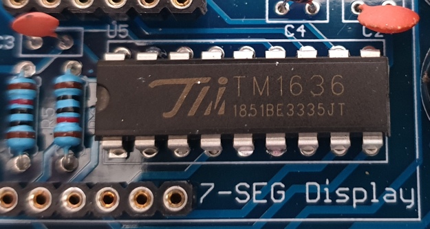
The Numerical LED Display
Our shield has a nice red four-digit, seven-segment LED clock display. We call it a clock display as there are colon LEDs between the second and third digit, just as a digital clock would usually have:
The TM1636 itself is an interesting part, so we’ll explain that in a separate tutorial in the near future. For now, back to the shield.
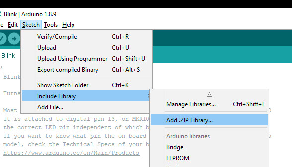
To control the LED display we need to install an Arduino library. In fact the shield needs four, so you can install them all at once now. Download the .zip file from here. Then expand that into your local download directory – it contains four library folders. You can then install them one at a time using the Arduino IDE’s Sketch > Include library > Add .zip library… command:
The supplied library offers five functions used to control the display.
.num(x);
…this displays a positive integer (whole number) between 0 and 9999.
.display(p,d);
… this shows a digit d in location p (locations from left to right are 3, 2, 1, 0)
.time(h,m)
… this is used to display time data (hours, minutes) easily. h is hours, m is minutes
.pointOn();
.pointOff();
… these turn the colon on … and off. And finally:
.clear();
… which clears the display to all off. At the start of the sketch, we need to use the library and initiate the instance of the display by inserting the following lines:
#include <TTSDisplay.h>
TTSDisplay rtcshield;
Don’t panic – the following sketch demonstrates the five functions described above:
#include<TTSDisplay.h>TTSDisplayrtcshield;inta=0;intb=0;voidsetup(){}voidloop(){// display some numbersfor(a=4921;a<5101;a++){rtcshield.num(a);delay(10);}// clear displayrtcshield.clear();// display individual digitsfor(a=3;a>=0;--a){rtcshield.display(a,a);delay(1000);rtcshield.clear();}for(a=3;a>=0;--a){rtcshield.display(a,a);delay(1000);rtcshield.clear();}// turn the colon and offfor(a=0;a<5;a++){rtcshield.pointOn();delay(500);rtcshield.pointOff();delay(500);}// demo the time display functionrtcshield.pointOn();rtcshield.time(11,57);delay(1000);rtcshield.time(11,58);delay(1000);rtcshield.time(11,59);delay(1000);rtcshield.time(12,00);delay(1000);}
And you can see it in action through the video below:
The LDR (Light Dependent Resistor)
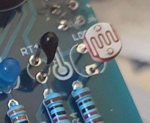
LDRs are useful for giving basic light level measurements, and our shield has one connected to analog input pin A1. It’s the two-legged item with the squiggle on top as shown below:
The resistance of LDRs change with light levels – the greater the light, the less the resistance. Thus by measuring the voltage of a current through the LDR with an analog input pin – you can get a numerical value proportional to the ambient light level. And that’s just what the following sketch does:
#include<TTSDisplay.h>TTSDisplayrtcshield;inta=0;voidsetup(){}voidloop(){// read value of analog inputa=analogRead(A1);// show value on displayrtcshield.num(a);delay(100);}
The Thermistor
A thermistor is a resistor whose resistance is relative to the ambient temperature. As the temperature increases, their resistance decreases. It’s the black part to the left of the LDR in the image below:
We can use this relationship between temperature and resistance to determine the ambient temperature. To keep things simple we won’t go into the theory – instead, just show you how to get a reading.
The thermistor circuit on our shield has the output connected to analog input zero, and we can use the library installed earlier to take care of the mathematics. Which just leaves us with the functions.
At the start of the sketch, we need to use the library and initiate the instance of the thermistor by inserting the following lines:
#include <TTSTemp.h>
TTSTemp temp;
… then use the following which returns a positive integer containing the temperature (so no freezing cold environments):
.get();
For our example, we’ll get the temperature and show it on the numerical display:
And our thermometer in action. No video this time… a nice 24 degrees C in the office:
The Real-Time Clock
Our shield is fitted with a DS1307 real-time clock IC circuit and backup battery holder. If you insert a CR1220 battery, the RTC will remember the settings even if you remove the shield from the Arduino or if there’s a power blackout, board reset etc:
The DS1307 is incredibly popular and used in many projects and found on many inexpensive breakout boards. We have a separate tutorial on how to use the DS1307, so instead of repeating ourselves – please visit our specific DS1307 Arduino tutorial, then return when finished.
Where to from here?
We can image there are many practical uses for this shield, which will not only improve your Arduino coding skills but also have some useful applications. An example is given below, that you can use for learning or fun.
Temperature Alarm
This projects turns the shield into a temperature monitor – you can select a lower and upper temperature, and if the temperature goes outside that range the buzzer can sound until you press it.
Here’s the sketch:
#include<TTSDisplay.h>#include<TTSTemp.h>TTSTemptemp;TTSDisplayrtcshield;booleanalarmOnOff=false;inthighTemp=40;intlowTemp=10;intcurrentTemp;voidLEDsoff(){// function to turn all alarm high/low LEDs offdigitalWrite(2,LOW);digitalWrite(4,LOW);}voidsetup(){// initalise digital pins for LEDs and buzzer as outputspinMode(2,OUTPUT);// LED 1pinMode(3,OUTPUT);// LED 2pinMode(4,OUTPUT);// LED 3pinMode(5,OUTPUT);// LED 4pinMode(6,OUTPUT);// buzzer// initalise digital pins for buttons as inputs// and initialise internal pullupspinMode(9,INPUT_PULLUP);// button K1pinMode(10,INPUT_PULLUP);// button K2pinMode(11,INPUT_PULLUP);// button K3}voidloop(){// get current temperaturecurrentTemp=temp.get();// if current temperature is within set limts// show temperature on displayif(currentTemp>=lowTemp||currentTemp<=highTemp)// if ambient temperature is less than high boundary// OR if ambient temperature is grater than low boundary// all is well{LEDsoff();// turn off LEDsrtcshield.num(currentTemp);}// if current temperature is above set high bounday, show red LED and// show temperature on display// turn on buzzer if alarm is set to on (button K3)if(currentTemp>highTemp){LEDsoff();// turn off LEDsdigitalWrite(4,HIGH);// turn on red LEDrtcshield.num(currentTemp);if(alarmOnOff==true){digitalWrite(6,HIGH);// buzzer on }}}// if current temperature is below set lower boundary, show blue LED and// show temperature on display// turn on buzzer if alarm is set to on (button K3)if(currentTemp<lowTemp){LEDsoff();// turn off LEDsdigitalWrite(2,HIGH);// turn on blue LEDrtcshield.num(currentTemp);if(alarmOnOff==true){digitalWrite(6,HIGH);// buzzer on }}}// --------turn alarm on or off-----------------------------------------------------if(digitalRead(11)==LOW)// turn alarm on or off{alarmOnOff=!alarmOnOff;if(alarmOnOff==0){digitalWrite(6,LOW);// turn off buzzerdigitalWrite(5,LOW);// turn off alarm on LED}// if alarm is set to on, turn LED on to indicate thisif(alarmOnOff==1){digitalWrite(5,HIGH);}delay(300);// software debounce}// --------set low temperature------------------------------------------------------if(digitalRead(10)==LOW)// set low temperature. If temp falls below this value, activate alarm{// clear display and turn on blue LED to indicate user is setting lower boundaryrtcshield.clear();digitalWrite(2,HIGH);// turn on blue LEDrtcshield.num(lowTemp);// user can press buttons K2 and K1 to decrease/increase lower boundary.// once user presses button K3, lower boundary is locked in and unit goes// back to normal statewhile(digitalRead(11)!=LOW)// repeat the following code until the user presses button K3{if(digitalRead(10)==LOW)// if button K2 pressed{--lowTemp;// subtract one from lower boundary// display new value. If this falls below zero, won't display. You can add checks for this yourself :)rtcshield.num(lowTemp);}if(digitalRead(9)==LOW)// if button K3 pressed{lowTemp++;// add one to lower boundary// display new value. If this exceeds 9999, won't display. You can add checks for this yourself :)rtcshield.num(lowTemp);}delay(300);// for switch debounce}digitalWrite(2,LOW);// turn off blue LED}// --------set high temperature-----------------------------------------------------if(digitalRead(9)==LOW)// set high temperature. If temp exceeds this value, activate alarm{// clear display and turn on red LED to indicate user is setting lower boundaryrtcshield.clear();digitalWrite(4,HIGH);// turn on red LEDrtcshield.num(highTemp);// user can press buttons K2 and K1 to decrease/increase upper boundary.// once user presses button K3, upper boundary is locked in and unit goes// back to normal statewhile(digitalRead(11)!=LOW)// repeat the following code until the user presses button K3{if(digitalRead(10)==LOW)// if button K2 pressed{--highTemp;// subtract one from upper boundary// display new value. If this falls below zero, won't display. You can add checks for this yourself :)rtcshield.num(highTemp);}if(digitalRead(9)==LOW)// if button K3 pressed{highTemp++;// add one to upper boundary// display new value. If this exceeds 9999, won't display. You can add checks for this yourself :)rtcshield.num(highTemp);}delay(300);// for switch debounce}digitalWrite(4,LOW);// turn off red LED}}
Operating instructions:
To set lower temperature, – press button K2. Blue LED turns on. Use buttons K2 and K1 to select temperature, then press K3 to lock it in. Blue LED turns off.
To set upper temperature – press button K1. Red LED turns on. Use buttons K2 and K1 to select temperature, then press K3 to lock it in. Red LED turns off.
If temperature drops below lower or exceeds upper temperature, the blue or red LED will come on.
You can have the buzzer sound when the alarm activates – to do this, press K3. When the buzzer mode is on, LED D4 will be on. You can turn buzzer off after it activates by pressing K3.
Display will show ambient temperature during normal operation.
You can see this in action via the video below:
Conclusion
This is a fun and useful shield – especially for beginners. It offers a lot of fun and options without any difficult coding or soldering – it’s easy to find success with the shield and increase your motivation to learn more and make more.
You can be serious with a clock, or annoy people with the buzzer. And at the time of writing you can have one for US$14.95, delivered. So go forth and create something.
A little research has shown that this shield was based from a product by Seeed, who discontinued it from sale. I’d like to thank them for the library.
This post brought to you by pmdway.com – everything for makers and electronics enthusiasts, with free delivery worldwide.
To keep up to date with new posts at tronixstuff.com, please subscribe to the mailing list in the box on the right, or follow us on twitter @tronixstuff.
Effects pedals: for some an object of overwhelming addiction, but for many, an opportunity to hack. Anyone who plays guitar (or buys presents for someone who does) knows of the infinite choice of pedals available. There are so many pedals because nailing the tone you hear in your head is an addictive quest, an itch that must be scratched. Rising to meet this challenge are a generation of programmable pedals that can tweak effects in clever ways.
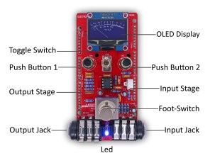
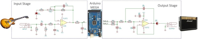
With this in mind, [ElectroSmash] are back at it with another open source offering: the pedalSHIELD MEGA. Aimed at musicians and hackers who want to learn more about audio, DSP and programming, this is an open-hardware/open-software shield for the Arduino MEGA which transforms it into an effects pedal.
The hardware consists of an analog input stage which amplifies and filters the incoming signal before passing it to the Arduino, as well as an output stage which does the DAC-ing from the Arduino’s PWM outputs, and some more filtering/amplifying. Two 8-bit PWM outputs are used simultaneously to make pseudo 16-bit resolution — a technique you can read more about in their handy forum guide.
The list of effects currently implemented covers all the basics you’d expect, and provides a good starting point for writing custom effects. Perhaps a library for some of the commonly used config/operations would be useful? Naturally, there are some computational constraints when using an Arduino for DSP, though it’s up to you whether this is a frustrating fact, or an opportunity to write some nicely optimised code.
There are two kinds of people in the world (and, no, this isn’t a binary joke). People who love the Arduino, and people who hate it. If you’ve ever tried to use a standard prototype board to mount on an Arduino, you’ll know what kind of person you are. When you notice the pins aren’t on 0.1 inch centers, you might think, “What the heck were those idiots thinking!” Or, you might say, “How clever! This way the connectors are keyed to prevent mistakes.” From your choice of statement, we can deduce your feelings on the subject.
[Rssalnero] clearly said something different. We weren’t there, but we suspect it was: “Gee. I should 3D print a jig to bend headers to fit.” Actually, he apparently tried to do it by hand (we’ve tried it, too). The results are not usually very good.
He created two simple 3D printed jigs that let you bend an 8-pin header. The first jig bends the correct offset and the second helps you straighten out the ends again. You can see the result in the picture above.
[Rssalnero] notes that the second jig needed reinforcement, so it is made to take 8 pins to use as fulcrums. Probably doesn’t hurt to print the jigs fairly solid and using harder plastic like ABS or PETG, too. Even if you don’t have a 3D printer, this is about a 15 or 30 minute print on any sort of reasonable printer, so make a friend. Worst case, you could have one of the 3D printing vendors make it for you, or buy local.
We love little tool hacks like this. If you are too lazy to snap 8 pins off a 40 pin strip, maybe you’d like some help. If you’d rather go with a custom PC board, you might start here.
Blood glucose monitors are pretty ubiquitous today. For most people with diabetes, these cheap and reliable sensors are their primary means of managing their blood sugar. But what is the enterprising diabetic hacker to do if he wakes up and realizes, with horror, that a primary aspect of his daily routine doesn’t involve an Arduino?
Rather than succumb to an Arduino-less reality, he can hopefully use the shield [M. Bindhammer] is working on to take his glucose measurement into his own hands.
[Bindhammer]’s initial work is based around the popular one-touch brand of strips. These are the cheapest, use very little blood, and the included needle is not as bad as it could be. His first challenge was just getting the connector for the strips. Naturally he could cannibalize a monitor from the pharmacy, but for someone making a shield that needs a supply line, this isn’t the best option. Surprisingly, the connectors used aren’t patented, so the companies are instead just more rigorous about who they sell them to. After a bit of work, he managed to find a source.
The next challenge is reverse engineering the actual algorithm used by the commercial sensor. It’s challenging. A simple mixture of water and glucose, for example, made the sensor throw an error. He’ll get it eventually, though, making this a great entry for the Hackaday Prize.
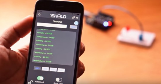
Have you ever thought of turning your iPhone and iPad into a platform of more than 40 Arduino shields? Now it’s possible!
The team of 1Sheeld have officially released the new 1Sheeld for iOS and it’s available for pre-orders for $39 instead of it’s original price $55 (shipping on May 2016).
You can control robots, actuators, display sensors’ data and much more. Take a look at the demo video:
So what’s the Arduino in there for? This is a digital Theremin, but check out the video below and you’ll agree that it sounds amazing and has excellent response. The aluminum antennas used for volume and pitch are attached to the top portion of the shield but it sounds like they’re not included in the kit. Don’t fret, you can use a variety of materials for this purpose. On the bottom you need to connect a speaker cable, and also a ground wire if that cable’s not grounded.
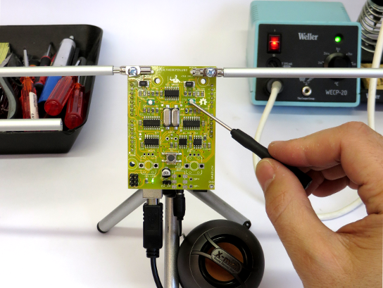
As the name implies, this is Open Hardware and we’re quite happy with the documentation on their site and the BOM (found on the GitHub repo). This design was shown off back in 2013 hiding in a pack of cigarettes. If you don’t want to build your own they’re selling kits on their site for 48 Euro delivered, or on Tindie for $55.
Okay, we’ve screwed this up so many times that we’re going to try to get it right here: the Theremin was not heard in the opening of Star Trek the original series, or in the opening of Doctor Who. It wasn’t featured in “Good Vibrations” either. As far as we can tell, it’s not used for anything in pop culture at all… but recognizing the sound and knowing what one is remains core geek knowledge.
Open.Theremin is an open source hardware and software project by Urs Gaudenz of Gaudi Lab with the aim of building the next digital generation of the legendary music instrument developed in the ’20s by the Russian inventor professor Leon Theremin. The project is documented under a open license and uses Open.Theremin.UNO, an Arduino or Genuino Uno shield featuring a digital mixer, combined 12 bit audio and CV out, audio jack on the bottom for more compact design, two completely separate antenna circuits:
The theremin is played with two antennas, one to control the pitch and one for volume. The electronic shield with two ports to connect those antennas comprises two heterodyne oscillators to measure the distance of the hand to the antenna when playing the instrument. The resulting signal is fed into the arduino. After linearization and filtering the arduino generates the instruments sound that is then played through a high quality digital analog audio converter on the board. The characteristics of the sound can be determined by a wave table on the arduino.
Most theremins on the market are either expensive or then not really playable. That’s how I decided to design a playable, open and affordable theremin. The first version was modular and difficult to program. Then I decided to redesign it as a shield to fit on the Arduino.UNO. This was a big success and many people could start using it, change the sounds and adapt it to their own application. The whole design is open source and documented on the website. I produced a small batch of the shield that can be bought through the small batch store on the website.
Watch the video below with Coralie Ehinger, a Swiss theremin player and organizer of the first Swiss theremin festival N / O / D / E, playing the instrument:
Planet Arduino is, or at the moment is wishing to become, an aggregation of public weblogs from around the world written by people who develop, play, think on Arduino platform and his son. The opinions expressed in those weblogs and hence this aggregation are those of the original authors. Entries on this page are owned by their authors. We do not edit, endorse or vouch for the contents of individual posts. For more information about Arduino please visit www.arduino.cc
You are currently browsing the archives for the shield category.