Posts | Comments

Planet Arduino

Archive for the ‘tronixstuff’ Category

The purpose of this guide is to get your 0.96″ color LCD display successfully operating with your Arduino, so you can move forward and experiment and explore further types of operation with the display. This includes installing the Arduino library, making a succesful board connection and running a demonstration sketch.

Although you can use the display with an Arduino Uno or other boad with an ATmega328-series microcontroller – this isn’t recommended for especially large projects. The library eats up a fair amount of flash memory – around 60% in most cases.

So if you’re running larger projects we recommend using an Arduino Mega or Due-compatible board due to the increased amount of flash memory in their host microcontrollers.

Installing the Arduino library

So let’s get started. We’ll first install the Arduino library then move on to hardware connection and then operating the display.

(As the display uses the ST7735S controller IC, you may be tempted to use the default TFT library included with the Arduino IDE – however it isn’t that reliable. Instead, please follow the instructions below). 

First – download the special Arduino library for your display and save it into your Downloads or a temp folder.

Next – open the Arduino IDE and select the Sketch > Include Library > Add .ZIP library option as shown below:
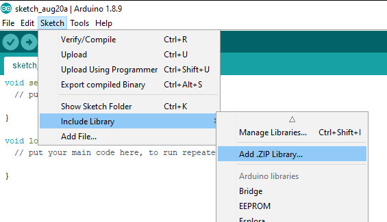
libraryinstall

A dialog box will open – navigate to and select the zip file you downloaded earlier. After a moment or two the IDE will then install the library.

Please check that the library has been installed – to do this, select the Sketch > Include Library option in the IDE and scroll down the long menu until you see “ER-TFTM0.96-1” as shown below:

libraryinstalled

Once that has been successful, you can wire up your display.

Connecting the display to your Arduino

The display uses the SPI data bus for communication, and is a 3.3V board. You can use it with an Arduino or other 5V board as the logic is tolerant of higher voltages.

Arduino to Display

GND ----- GND (GND)
3.3V ---- Vcc (3.3V power supply)
D13 ----- SCL (SPI bus clock)
D11 ----- SDA (SPI bus data out from Arduino)
D10 ----- CS (SPI bus "Chip Select")
D9 ------ DC (Data instruction select pin)
D8 ------ RES (reset input)

If your Arduino has different pinouts than the Uno, locate the SPI pins for your board and modify as appropriate.

Demonstration sketch

Open a new sketch in the IDE, then copy and paste the following sketch into the IDE:

// https://pmdway.com/products/0-96-80-x-160-full-color-lcd-module
#include <UTFT.h>

// Declare which fonts we will be using
extern uint8_t SmallFont[];

// Initialize display
// Library only supports software SPI at this time
//NOTE: support  DUE , MEGA , UNO 
//SDI=11  SCL=13  /CS =10  /RST=8  D/C=9
UTFT myGLCD(ST7735S_4L_80160,11,13,10,8,9);    //LCD:  4Line  serial interface      SDI  SCL  /CS  /RST  D/C    NOTE:Only support  DUE   MEGA  UNO

// Declare which fonts we will be using
extern uint8_t BigFont[];

int color = 0;
word colorlist[] = {VGA_WHITE, VGA_BLACK, VGA_RED, VGA_BLUE, VGA_GREEN, VGA_FUCHSIA, VGA_YELLOW, VGA_AQUA};
int  bsize = 4;

void drawColorMarkerAndBrushSize(int col)
{
  myGLCD.setColor(VGA_BLACK);
  myGLCD.fillRect(25, 0, 31, 239);
  myGLCD.fillRect(myGLCD.getDisplayXSize()-31, 161, myGLCD.getDisplayXSize()-1, 191);
  myGLCD.setColor(VGA_WHITE);
  myGLCD.drawPixel(25, (col*30)+15);
  for (int i=1; i<7; i++)
    myGLCD.drawLine(25+i, ((col*30)+15)-i, 25+i, ((col*30)+15)+i);
  
  if (color==1)
    myGLCD.setColor(VGA_WHITE);
  else
    myGLCD.setColor(colorlist[col]);
  if (bsize==1)
    myGLCD.drawPixel(myGLCD.getDisplayXSize()-15, 177);
  else
    myGLCD.fillCircle(myGLCD.getDisplayXSize()-15, 177, bsize);
    
  myGLCD.setColor(colorlist[col]);
}
void setup()
{
  randomSeed(analogRead(0));
  
// Setup the LCD
  myGLCD.InitLCD();
  myGLCD.setFont(SmallFont);
}

void loop()
{
  int buf[158];
  int x, x2;
  int y, y2;
  int r;

// Clear the screen and draw the frame
  myGLCD.clrScr();

  myGLCD.setColor(255, 0, 0);
  myGLCD.fillRect(0, 0, 159, 13);
  myGLCD.setColor(64, 64, 64);
  myGLCD.fillRect(0, 114, 159, 127);
  myGLCD.setColor(255, 255, 255);
  myGLCD.setBackColor(255, 0, 0);
  myGLCD.print("pmdway.com.", CENTER, 1);
  myGLCD.setBackColor(64, 64, 64);
  myGLCD.setColor(255,255,0);
  myGLCD.print("pmdway.com", LEFT, 114);


  myGLCD.setColor(0, 0, 255);
  myGLCD.drawRect(0, 13, 159, 113);

// Draw crosshairs
  myGLCD.setColor(0, 0, 255);
  myGLCD.setBackColor(0, 0, 0);
  myGLCD.drawLine(79, 14, 79, 113);
  myGLCD.drawLine(1, 63, 158, 63);
  
 myGLCD.setColor(0, 0, 255);
 myGLCD.drawLine(0, 79, 159, 79);
 
  for (int i=9; i<150; i+=10)
    myGLCD.drawLine(i, 61, i, 65);
  for (int i=19; i<110; i+=10)
    myGLCD.drawLine(77, i, 81, i);
    

// Draw sin-, cos- and tan-lines  
  myGLCD.setColor(0,255,255);
  myGLCD.print("Sin", 5, 15);
  for (int i=1; i<158; i++)
  {
    myGLCD.drawPixel(i,63+(sin(((i*2.27)*3.14)/180)*40));
  }
  
  myGLCD.setColor(255,0,0);
  myGLCD.print("Cos", 5, 27);
  for (int i=1; i<158; i++)
  {
    myGLCD.drawPixel(i,63+(cos(((i*2.27)*3.14)/180)*40));
  }

  myGLCD.setColor(255,255,0);
  myGLCD.print("Tan", 5, 39);
  for (int i=1; i<158; i++)
  {
    myGLCD.drawPixel(i,63+(tan(((i*2.27)*3.14)/180)));
  }

  delay(2000);

  myGLCD.setColor(0,0,0);
  myGLCD.fillRect(1,14,158,113);
  myGLCD.setColor(0, 0, 255);
  myGLCD.setBackColor(0, 0, 0);
  myGLCD.drawLine(79, 14, 79, 113);
  myGLCD.drawLine(1, 63, 158, 63);

 myGLCD.setColor(0, 0, 255);
 myGLCD.drawLine(0, 79, 159, 79);  

// Draw a moving sinewave
  x=1;
  for (int i=1; i<(158*20); i++) 
  {
    x++;
    if (x==159)
      x=1;
    if (i>159)
    {
      if ((x==79)||(buf[x-1]==63))
        myGLCD.setColor(0,0,255);
      else
        myGLCD.setColor(0,0,0);
      myGLCD.drawPixel(x,buf[x-1]);
    }
    myGLCD.setColor(0,255,255);
    y=63+(sin(((i*2.5)*3.14)/180)*(40-(i / 100)));
    myGLCD.drawPixel(x,y);
    buf[x-1]=y;
  }

  delay(2000);
 
  myGLCD.setColor(0,0,0);
  myGLCD.fillRect(1,14,158,113);
  
 myGLCD.setColor(0, 0, 255);
 myGLCD.drawLine(0, 79, 159, 79);  

// Draw some filled rectangles
  for (int i=1; i<6; i++)
  {
    switch (i)
    {
      case 1:
        myGLCD.setColor(255,0,255);
        break;
      case 2:
        myGLCD.setColor(255,0,0);
        break;
      case 3:
        myGLCD.setColor(0,255,0);
        break;
      case 4:
        myGLCD.setColor(0,0,255);
        break;
      case 5:
        myGLCD.setColor(255,255,0);
        break;
    }
    myGLCD.fillRect(39+(i*10), 23+(i*10), 59+(i*10), 43+(i*10));
  }

  delay(2000);
  
  myGLCD.setColor(0,0,0);
  myGLCD.fillRect(1,14,158,113);
  myGLCD.setColor(0, 0, 255);
 myGLCD.drawLine(0, 79, 159, 79);   

// Draw some filled, rounded rectangles
  for (int i=1; i<6; i++)
  {
    switch (i)
    {
      case 1:
        myGLCD.setColor(255,0,255);
        break;
      case 2:
        myGLCD.setColor(255,0,0);
        break;
      case 3:
        myGLCD.setColor(0,255,0);
        break;
      case 4:
        myGLCD.setColor(0,0,255);
        break;
      case 5:
        myGLCD.setColor(255,255,0);
        break;
    }
    myGLCD.fillRoundRect(99-(i*10), 23+(i*10), 119-(i*10), 43+(i*10));
  }

  delay(2000);
  
  myGLCD.setColor(0,0,0);
  myGLCD.fillRect(1,14,158,113);

 myGLCD.setColor(0, 0, 255);
 myGLCD.drawLine(0, 79, 159, 79);  
// Draw some filled circles
  for (int i=1; i<6; i++)
  {
    switch (i)
    {
      case 1:
        myGLCD.setColor(255,0,255);
        break;
      case 2:
        myGLCD.setColor(255,0,0);
        break;
      case 3:
        myGLCD.setColor(0,255,0);
        break;
      case 4:
        myGLCD.setColor(0,0,255);
        break;
      case 5:
        myGLCD.setColor(255,255,0);
        break;
    }
    myGLCD.fillCircle(49+(i*10),33+(i*10), 15);
  }

  delay(2000);
    
  myGLCD.setColor(0,0,0);
  myGLCD.fillRect(1,14,158,113);
  
 myGLCD.setColor(0, 0, 255);
 myGLCD.drawLine(0, 79, 159, 79);    

// Draw some lines in a pattern
  myGLCD.setColor (255,0,0);
  for (int i=14; i<113; i+=5)
  {
    myGLCD.drawLine(1, i, (i*1.44)-10, 112);
  }
  myGLCD.setColor (255,0,0);
  for (int i=112; i>15; i-=5)
  {
    myGLCD.drawLine(158, i, (i*1.44)-12, 14);
  }
  myGLCD.setColor (0,255,255);
  for (int i=112; i>15; i-=5)
  {
    myGLCD.drawLine(1, i, 172-(i*1.44), 14);
  }
  myGLCD.setColor (0,255,255);
  for (int i=15; i<112; i+=5)
  {
    myGLCD.drawLine(158, i, 171-(i*1.44), 112);
  }

  delay(2000);
  
  myGLCD.setColor(0,0,0);
  myGLCD.fillRect(1,14,158,113);
  
 myGLCD.setColor(0, 0, 255);
 myGLCD.drawLine(0, 79, 159, 79);    

// Draw some random circles
  for (int i=0; i<100; i++)
  {
    myGLCD.setColor(random(255), random(255), random(255));
    x=22+random(116);
    y=35+random(57);
    r=random(20);
    myGLCD.drawCircle(x, y, r);
  }

  delay(2000);
  
  myGLCD.setColor(0,0,0);
  myGLCD.fillRect(1,14,158,113);
  
 myGLCD.setColor(0, 0, 255);
 myGLCD.drawLine(0, 79, 159, 79);    
  

// Draw some random rectangles
  for (int i=0; i<100; i++)
  {
    myGLCD.setColor(random(255), random(255), random(255));
    x=2+random(156);
    y=16+random(95);
    x2=2+random(156);
    y2=16+random(95);
    myGLCD.drawRect(x, y, x2, y2);
  }

  delay(2000);
  
  myGLCD.setColor(0,0,0);
  myGLCD.fillRect(1,14,158,113);
  
 myGLCD.setColor(0, 0, 255);
 myGLCD.drawLine(0, 79, 159, 79);    

// Draw some random rounded rectangles
  for (int i=0; i<100; i++)
  {
    myGLCD.setColor(random(255), random(255), random(255));
    x=2+random(156);
    y=16+random(95);
    x2=2+random(156);
    y2=16+random(95);
    myGLCD.drawRoundRect(x, y, x2, y2);
  }

  delay(2000);
  
  myGLCD.setColor(0,0,0);
  myGLCD.fillRect(1,14,158,113);
  
 myGLCD.setColor(0, 0, 255);
 myGLCD.drawLine(0, 79, 159, 79);  
 
  for (int i=0; i<100; i++)
  {
    myGLCD.setColor(random(255), random(255), random(255));
    x=2+random(156);
    y=16+random(95);
    x2=2+random(156);
    y2=16+random(95);
    myGLCD.drawLine(x, y, x2, y2);
  }

  delay(2000);
  
  myGLCD.setColor(0,0,0);
  myGLCD.fillRect(1,14,158,113);
  
 myGLCD.setColor(0, 0, 255);
 myGLCD.drawLine(0, 79, 159, 79);  
 
  for (int i=0; i<5000; i++)
  {
    myGLCD.setColor(random(255), random(255), random(255));
    myGLCD.drawPixel(2+random(156), 16+random(95));
  }

  delay(2000);

  myGLCD.fillScr(0, 0, 255);
  myGLCD.setColor(255, 0, 0);
  myGLCD.fillRoundRect(10, 17, 149, 72);
  
  myGLCD.setColor(255, 255, 255);
  myGLCD.setBackColor(255, 0, 0);
  myGLCD.print("That's it!", CENTER, 20);
  myGLCD.print("Restarting in a", CENTER, 45);
  myGLCD.print("few seconds...", CENTER, 57);
  
  myGLCD.setColor(0, 255, 0);
  myGLCD.setBackColor(0, 0, 255);
  myGLCD.print("Runtime: (msecs)", CENTER, 103);
  myGLCD.printNumI(millis(), CENTER, 115);

  delay (5000);   
}


Once you’re confident with the physical connection, upload the sketch. It should result with output as shown in the video below:

Now that you have succesfully run the demonstration sketch – where to from here?

The library used is based on the uTFT library by Henning Karlsen. You can find all the drawing and other commands in the user manual – so download the pdf and enjoy creating interesting displays.

This post brought to you by pmdway.com – everything for makers and electronics enthusiasts, with free delivery worldwide.

To keep up to date with new posts at tronixstuff.com, please subscribe to the mailing list in the box on the right, or follow us on twitter @tronixstuff.

The purpose of this guide is to have an SSD1306-based OLED display successfully operating with your Arduino, so you can move forward and experiment and explore further types of operation with the display.

This includes installing the Arduino library, making a succesful board connection and running a demonstration sketch. So let’s get started!

Connecting the display to your Arduino

The display uses the I2C data bus for communication, and is a 5V and 3.3V-tolerant board.

Arduino Uno to Display

GND ---- GND (GND)
5V/3.3V- Vcc (power supply, can be 3.3V or 5V)
A5 ----- SCL (I2C bus clock)
A4 ----- SDA (I2C bus data)

I2C pinouts vary for other boards. Arduino Leonard uses D2/D3 for SDA and SCL or the separate pins to the left of D13. Arduino Mega uses D20/D21 for SDA and SCL. If you can’t find your I2C pins on other boards, ask your display supplier.

Installing the Arduino library

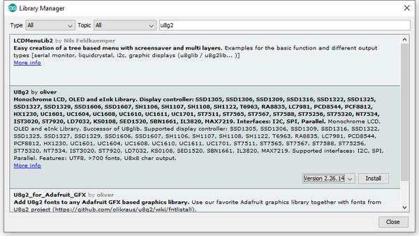
To install the library – simply open the Arduino IDE and select Manage Libraries… from the Tools menu. Enter “u8g2” in the search box, and after a moment it should appear in the results as shown in the image below. Click on the library then click “Install”:

install-library-u8g2

After a moment the library will be installed and you can close that box.

Now it’s time to check everything necessary is working. Open a new sketch in the IDE, then copy and paste the following sketch into the IDE:

// Display > https://pmdway.com/products/0-96-128-64-graphic-oled-displays-i2c-or-spi-various-colors

#include <Arduino.h>
#include <U8x8lib.h>

#ifdef U8X8_HAVE_HW_SPI
#include <SPI.h>
#endif
#ifdef U8X8_HAVE_HW_I2C
#include <Wire.h>
#endif

  U8X8_SSD1306_128X64_NONAME_HW_I2C u8x8(/* reset=*/ U8X8_PIN_NONE);   

/*
  This example will probably not work with the SSD1606, because of the
  internal buffer swapping
*/

void setup(void)
{
  /* U8g2 Project: KS0108 Test Board */
  //pinMode(16, OUTPUT);
  //digitalWrite(16, 0);  

  /* U8g2 Project: Pax Instruments Shield: Enable Backlight */
  //pinMode(6, OUTPUT);
  //digitalWrite(6, 0); 

  u8x8.begin();
  //u8x8.setFlipMode(1);
}

void pre(void)
{
  u8x8.setFont(u8x8_font_amstrad_cpc_extended_f);    
  u8x8.clear();

  u8x8.inverse();
  u8x8.print(" U8x8 Library ");
  u8x8.setFont(u8x8_font_chroma48medium8_r);  
  u8x8.noInverse();
  u8x8.setCursor(0,1);
}

void draw_bar(uint8_t c, uint8_t is_inverse)
{ 
  uint8_t r;
  u8x8.setInverseFont(is_inverse);
  for( r = 0; r < u8x8.getRows(); r++ )
  {
    u8x8.setCursor(c, r);
    u8x8.print(" ");
  }
}

void draw_ascii_row(uint8_t r, int start)
{
  int a;
  uint8_t c;
  for( c = 0; c < u8x8.getCols(); c++ )
  {
    u8x8.setCursor(c,r);
    a = start + c;
    if ( a <= 255 )
      u8x8.write(a);
  }
}

void loop(void)
{
  int i;
  uint8_t c, r, d;
  pre();
  u8x8.print("github.com/");
  u8x8.setCursor(0,2);
  u8x8.print("olikraus/u8g2");
  delay(2000);
  u8x8.setCursor(0,3);
  u8x8.print("Tile size:");
  u8x8.print((int)u8x8.getCols());
  u8x8.print("x");
  u8x8.print((int)u8x8.getRows());
  
  delay(2000);
   
  pre();
  for( i = 19; i > 0; i-- )
  {
    u8x8.setCursor(3,2);
    u8x8.print(i);
    u8x8.print("  ");
    delay(150);
  }
  
  draw_bar(0, 1);
  for( c = 1; c < u8x8.getCols(); c++ )
  {
    draw_bar(c, 1);
    draw_bar(c-1, 0);
    delay(50);
  }
  draw_bar(u8x8.getCols()-1, 0);

  pre();
  u8x8.setFont(u8x8_font_amstrad_cpc_extended_f); 
  for( d = 0; d < 8; d ++ )
  {
    for( r = 1; r < u8x8.getRows(); r++ )
    {
      draw_ascii_row(r, (r-1+d)*u8x8.getCols() + 32);
    }
    delay(400);
  }

  draw_bar(u8x8.getCols()-1, 1);
  for( c = u8x8.getCols()-1; c > 0; c--)
  {
    draw_bar(c-1, 1);
    draw_bar(c, 0);
    delay(50);
  }
  draw_bar(0, 0);

  pre();
  u8x8.drawString(0, 2, "Small");
  u8x8.draw2x2String(0, 5, "Scale Up");
  delay(3000);

  pre();
  u8x8.drawString(0, 2, "Small");
  u8x8.setFont(u8x8_font_px437wyse700b_2x2_r);
  u8x8.drawString(0, 5, "2x2 Font");
  delay(3000);

  pre();
  u8x8.drawString(0, 1, "3x6 Font");
  u8x8.setFont(u8x8_font_inb33_3x6_n);
  for(i = 0; i < 100; i++ )
  {
    u8x8.setCursor(0, 2);
    u8x8.print(i);      // Arduino Print function
    delay(10);
  }
  for(i = 0; i < 100; i++ )
  {
    u8x8.drawString(0, 2, u8x8_u16toa(i, 5)); // U8g2 Build-In functions
    delay(10);    
  }

  pre();
  u8x8.drawString(0, 2, "Weather");
  u8x8.setFont(u8x8_font_open_iconic_weather_4x4);
  for(c = 0; c < 6; c++ )
  {
    u8x8.drawGlyph(0, 4, '@'+c);
    delay(300);
  }
  

  pre();
  u8x8.print("print \\n\n");
  delay(500);
  u8x8.println("println");
  delay(500);
  u8x8.println("done");
  delay(1500);

  pre();
  u8x8.fillDisplay();
  for( r = 0; r < u8x8.getRows(); r++ )
  {
    u8x8.clearLine(r);
    delay(100);
  }
  delay(1000);
}

Your display should go through the demonstration of various things as shown in the video below:

If the display did not work – you may need to manually set the I2C bus address. To do this, wire up your OLED then run this sketch (open the serial monitor for results). It’s an I2C scanner tool that will return the I2C bus display. 

Then use the following line in void setup():

u8x8.setI2CAddress(address)

Replace u8x8 with your display reference, and address with the I2C bus address (for example. 0x17).

Moving on…

By now you have an idea of what is possible with these great-value displays.

Now your display is connected and working, it’s time to delve deeper into the library and the various modes of operations. There are three, and they are described in the library documentation – click here to review them

Whenever you use one of the three modes mentioned above, you need to use one of the following constructor lines:

U8G2_SSD1306_128X64_NONAME_F_HW_I2C u8g2(U8G2_R0, /* reset=*/ U8X8_PIN_NONE); // full buffer mode

U8X8_SSD1306_128X64_NONAME_HW_I2C u8x8(/* reset=*/ U8X8_PIN_NONE); // 8x8 character mode

U8G2_SSD1306_128X64_NONAME_1_HW_I2C u8g2(U8G2_R0, /* reset=*/ U8X8_PIN_NONE); // page buffer mode

Match the mode you wish to use with one of the constructors above. For example, in the demonstration sketch you ran earlier, we used the 8×8 character mode constructor in line 14.

Where to from here?

Now it’s time for you to explore the library reference guide which explains all the various functions available to create text and graphics on the display, as well as the fonts and so on. These can all be found on the right-hand side of the driver wiki page.

This post brought to you by pmdway.com – everything for makers and electronics enthusiasts, with free delivery worldwide.

To keep up to date with new posts at tronixstuff.com, please subscribe to the mailing list in the box on the right, or follow us on twitter @tronixstuff.
Introduction

There are many ways of remotely-controlling your Arduino or compatible hardware over the Internet. Some are more complex than others, which can be a good thing or a bad thing depending on your level of expertise. Lately we’ve become more interested in this topic and have come across Blynk, which appeared to be a simple solution – and thus the topic of our review.

What is Blynk?

From their website: “Blynk is a Platform with iOS and Android apps to control Arduino, Raspberry Pi and the likes over the Internet. It’s a digital dashboard where you can build a graphic interface for your project by simply dragging and dropping widgets. 

It’s really simple to set everything up and you’ll start tinkering in less than 5 mins. Blynk is not tied to some specific board or shield. Instead, it’s supporting hardware of your choice. Whether your Arduino or Raspberry Pi is linked to the Internet over Wi-Fi, Ethernet or this new ESP8266 chip, Blynk will get you online and ready for the Internet Of Your Things.” Here is the original launch video:

Blynk started off as an idea, and raised initial funding through Kickstarter – which was successful and the system has now launched. Blynk comprises of an app on your smartphone (Android or iOS) inside which you can add widgets (controls) to send commands back to your development board (Arduino etc.).

For example, you can add a switch to turn a digital output on or off. Furthermore, data from sensors connected to the development board can be send back to the smartphone. The data passes through the Blynk Cloud server, or you can download and run your own server on your own hardware and infrastructure.

How much does it cost?

Right now (September 2015) the Blynk system is free. We downloaded the app and experimented without charge. We believe that over time there will be payment required for various functions, however you can try it out now to see if Blynk suits your needs then run with it later or experiment with other platforms.

Getting Started

Well enough talk, let’s try Blynk out. Our hardware is an Android smartphone (the awesome new Oppo R7+) for control, and a Freetronics EtherTen connected to our office modem/router:

blynk etherten tronixstuff

You can also use other Arduino+Ethernet combinations, such as an Arduino Uno with an Ethernet shield. First you need to download the app for your phone – click here for the links. Then from the same page, download the Arduino library – and install it like you would any other Arduino library.

For our first example, we’ll use an LED connected to digital pin 7 (via a 560 ohm resistor) shown above. Now it’s time to set up the Blynk app. When you run the app for the first time, you need to sign in – so enter an email address and password:

blynk tronixstuff 1

Then click the “+” at the top-right of the display to create a new project, and you should see the following screen:

blynk tronixstuff 2

You can name your project, select the target hardware (Arduino Uno) – then click “E-mail” to send that auth token to yourself – you will need it in a moment. Then click “Create” to enter the main app design screen. Next, press “+” again to get the “Widget Box” menu as shown below, then press “Button”:

blynk tronixstuff 3

This will place a simple button on your screen:

blynk tronixstuff 4

Press the button to open its’ settings menu:

blynk tronixstuff 5

From this screen you can name your button, and also determine whether it will be “momentary” (i.e., only on when you press the button) – or operate as a switch (push on… push off…). Furthermore you need to select which physical Arduino pin the button will control – so press “PIN”, which brings up the scrolling menu as shown below:

blynk tronixstuff 6

We set ours to D7 then pressed “Continue”. Now the app is complete. Now head back to your computer, open the Arduino IDE, and load the “Arduino_Ethernet” sketch included with the library:

blynk example sketch tronixstuff

Then scroll down to line 30 and enter the auth key that was sent to you via email:

blynk example sketch tronixstuff auth key

Save then upload the sketch to your Arduino. Now head back to your smartphone, and click the “Play” (looks like a triangle pointing right) button. After a moment the app will connect to the Blynk server… the Arduino will also be connected to the server – and you can press the button on the screen to control the LED.

And that’s it – remote control really is that easy. We’ve run through the process in the following short video:

Now what else can we control? How about some IKEA LED strips from our last article. Easy… that consisted of three digital outputs, with PWM. The app resembles the following:

blynk tronixstuff ikea dioder

… and watch the video below to see it in action:

Monitoring data from an Arduino via Blynk

Data can also travel in the other direction – from your Arduino over the Internet to your smartphone. At the time of writing this (September 2015) you can monitor the status of analogue and digital pins, and widgets can be added in the app to do just that. They can display the value returned from each ADC, which falls between zero and 1023 – and display the values in various forms – for example:

blynk sensors tronixstuff

The bandwidth required for this is just under 2 K/s, as you can see from the top of the image above. You can see this in action through the video below:

Conclusion

We have only scratched the surface of what is possible with Blynk – which is an impressive, approachable and usable “Internet of Things” platform. Considering that you can get an inexpensive Android smartphone or tablet for under AU$50, the overall cost of using Blynk is excellent and well worth consideration, even just to test out the “Internet of Things” buzz yourself. So to get started head over to the Blynk site.

Introduction

A few weeks ago I found a DIODER LED strip set from a long-ago trek to IKEA, and considered that something could be done with it.  So in this article you can see how easy it is to control the LEDs using an Arduino or compatible board with ease… opening it up to all sorts of possibilities.

This is not the most original project – however things have been pretty quiet around here, so I thought it was time to share something new with you. Furthermore the DIODER control PCB has changed, so this will be relevant to new purchases. Nevertheless, let’s get on with it.

So what is DIODER anyhow? 

As you can see in the image below, the DIODER pack includes four RGB LED units each with nine RGB LEDs per unit. A controller box allows power and colour choice, a distribution box connects between the controller box and the LED strips, and the whole thing is powered by a 12V DC plugpack:

IKEA DIODER LED strips

The following is a quick video showing the DIODER in action as devised by IKEA:


Thankfully the plugpack keeps us away from mains voltages, and includes a long detachable cable which connects to the LED strip distribution box. The first thought was to investigate the controller, and you can open it with a standard screwdriver. Carefully pry away the long-side, as two clips on each side hold it together…

IKEA DIODER Arduino tronixstuff
… which reveals the PCB. Nothing too exciting here – you can see the potentiometer used for changing the lighting effects, power and range buttons and so on:

ikea dioder tronixstuff arduino

Our DIODER has the updated PCB with the Chinese market microcontroller. If you have an older DIODER with a Microchip PIC – you can reprogram it yourself.

ikea dioder arduino tronixstuff

The following three MOSFETs are used to control the current to each of the red, green and blue LED circuits. These will be the key to controlling the DIODER’s strips – but are way too small for me to solder to. The original plan was to have an Arduino’s PWM outputs tap into the MOSFET’s gates – but instead I will use external MOSFETs.

ikea dioder arduino tronixstuff

So what’s a MOSFET?

In the past you may have used a transistor to switch higher current from an Arduino, however a MOSFET is a better solution for this function. The can control large voltages and high currents without any effort. We will use N-channel MOSFETs, which have three pins – Source, Drain and Gate. When the Gate is HIGH, current will flow into the Drain and out of the Source:

mosfet

A simplistic explanation is that it can be used like a button – and when wiring your own N-MOSFET a 10k resistor should be used between Gate and Drain to keep the Gate low when the Arduino output is set to LOW (just like de-bouncing a button). To learn more about MOSFETS – get yourself a copy of “The Art of Electronics“. It is worth every cent.

However being somewhat time poor (lazy?), I have instead used a Freetronics NDrive Shield for Arduino – which contains six N-MOSFETs all on one convenient shield  – with each MOSFET’s Gate pin connected to an Arduino PWM output.
freetronics ndrive shield tronixlabs

So let’s head back to the LED strips for a moment, in order to determine how the LEDs are wired in the strip. Thanks to the manufacturer – the PCB has the markings as shown below:

ikea dioder tronixstuff arduino

They’re 12V LEDs in a common-anode configuration. How much current do they draw? Depends on how many strips you have connected together…

ikea dioder arduino tronixstuff

For the curious I measured each colour at each length, with the results in the following table:

current

So all four strips turned on, with all colours on – the strips will draw around 165 mA of current at 12V. Those blue LEDs are certainly thirsty.

Moving on, the next step is to connect the strips to the MOSFET shield. This is easy thanks to the cable included in the DIODER pack, just chop the white connector off as shown below:

ikea dioder arduino tronixstuff

By connecting an LED strip to the other end of the cable you can then determine which wire is common, and which are the cathodes for red, green and blue.

The plugpack included with the DIODER pack can be used to power the entire project, so you will need cut the DC plug (the plug that connects into the DIODER’s distribution box) off the lead, and use a multimeter to determine which wire is negative, and which is positive.

Connect the negative wire to the GND terminal on the shield, and the positive wire to the Vin terminal.  Then…

  • the red LED wire to the D3 terminal,
  • the green LED wire to the D9 terminal,
  • and the blue LED wire to the D10 terminal.

Finally, connect the 12V LED wire (anode) into the Vin terminal. Now double-check your wiring. Then check it again.

ikea dioder tronixstuff arduino

Testing

Now to run a test sketch to show the LED strip can easily be controlled. We’ll turn each colour on and off using PWM (Pulse-Width Modulation) – a neat way to control the brightness of each colour. The following sketch will pulse each colour in turn, and there’s also a blink function you can use.

// Controlling IKEA DIODER LED strips with Arduino and Freetronics NDRIVE N-MOSFET shield
// CC by-sa-nc John Boxall 2015 - tronixstuff.com 
// Components from tronixlabs.com

#define red 3
#define green 9
#define blue 10
#define delaya 2

void setup() 
{
  pinMode(red, OUTPUT);
  pinMode(green, OUTPUT);
  pinMode(blue, OUTPUT);
}

void blinkRGB()
{
  digitalWrite(red, HIGH);
  delay(1000);
  digitalWrite(red, LOW);
  digitalWrite(green, HIGH);
  delay(1000);
  digitalWrite(green, LOW);
  digitalWrite(blue, HIGH);
  delay(1000);
  digitalWrite(blue, LOW);
}

void pulseRed()
{
  for (int i=0; i<256; i++)
  {
    analogWrite(red,i);
    delay(delaya);
  }
  for (int i=255; i>=0; --i)
  {
    analogWrite(red,i);
    delay(delaya);
  }
}

void pulseGreen()
{
  for (int i=0; i<256; i++)
  {
    analogWrite(green,i);
    delay(delaya);
  }
  for (int i=255; i>=0; --i)
  {
    analogWrite(green,i);
    delay(delaya);
  }
}

void pulseBlue()
{
  for (int i=0; i<256; i++)
  {
    analogWrite(blue,i);
    delay(delaya);
  }
  for (int i=255; i>=0; --i)
  {
    analogWrite(blue,i);
    delay(delaya);
  }
}

void loop()
{
  pulseRed();
  pulseGreen();
  pulseBlue();
}

Success. And for the non-believers, watch the following video:

Better LED control

As always, there’s a better way of doing things and one example of LED control is the awesome FASTLED library by Daniel Garcia and others. Go and download it now – https://github.com/FastLED/FastLED. Apart from our simple LEDS, the FASTLED library is also great with WS2812B/Adafruit NeoPixels and others.

One excellent demonstration included with the library is the AnalogOutput sketch, which I have supplied below to work with our example hardware:

#include <FastLED.h>

// Example showing how to use FastLED color functions
// even when you're NOT using a "pixel-addressible" smart LED strip.
//
// This example is designed to control an "analog" RGB LED strip
// (or a single RGB LED) being driven by Arduino PWM output pins.
// So this code never calls FastLED.addLEDs() or FastLED.show().
//
// This example illustrates one way you can use just the portions 
// of FastLED that you need.  In this case, this code uses just the
// fast HSV color conversion code.
// 
// In this example, the RGB values are output on three separate
// 'analog' PWM pins, one for red, one for green, and one for blue.
 
#define REDPIN   3
#define GREENPIN 9
#define BLUEPIN  10

// showAnalogRGB: this is like FastLED.show(), but outputs on 
// analog PWM output pins instead of sending data to an intelligent,
// pixel-addressable LED strip.
// 
// This function takes the incoming RGB values and outputs the values
// on three analog PWM output pins to the r, g, and b values respectively.
void showAnalogRGB( const CRGB& rgb)
{
  analogWrite(REDPIN,   rgb.r );
  analogWrite(GREENPIN, rgb.g );
  analogWrite(BLUEPIN,  rgb.b );
}


// colorBars: flashes Red, then Green, then Blue, then Black.
// Helpful for diagnosing if you've mis-wired which is which.
void colorBars()
{
  showAnalogRGB( CRGB::Red );   delay(500);
  showAnalogRGB( CRGB::Green ); delay(500);
  showAnalogRGB( CRGB::Blue );  delay(500);
  showAnalogRGB( CRGB::Black ); delay(500);
}

void loop() 
{
  static uint8_t hue;
  hue = hue + 1;
  // Use FastLED automatic HSV->RGB conversion
  showAnalogRGB( CHSV( hue, 255, 255) );
  
  delay(20);
}


void setup() {
  pinMode(REDPIN,   OUTPUT);
  pinMode(GREENPIN, OUTPUT);
  pinMode(BLUEPIN,  OUTPUT);

  // Flash the "hello" color sequence: R, G, B, black.
  colorBars();
}

You can see this in action through the following video:

Control using a mobile phone?

Yes – click here to learn how.

Conclusion

So if you have some IKEA LED strips, or anything else that requires more current than an Arduino’s output pin can offer – you can use MOSFETs to take over the current control and have fun. And finally a plug for my own store – tronixlabs.com – offering a growing range and Australia’s best value for supported hobbyist electronics from adafruit, DFRobot, Freetronics, Seeed Studio and much much more.

visit tronixlabs.com

As always, have fun and keep checking into tronixstuff.com. Why not follow things on twitterGoogle+, subscribe  for email updates or RSS using the links on the right-hand column, or join our forum – dedicated to the projects and related items on this website.

We keep getting requests on how to use DS1307 and DS3231 real-time clock modules with Arduino from various sources – so this is the first of a two part tutorial on how to use them. For this Arduino tutorial we have  two real-time clock modules to use, one based on the Maxim DS1307:

ds1307-real-time-clock-module-from-tronixlabs-australia

and another based on the DS3231:

ds3231-real-time-clock-module-from-tronixlabs-australia

There are two main differences between the ICs on the real-time clock modules, which is the accuracy of the time-keeping. The DS1307 used in the first module works very well, however the external temperature can affect the frequency of the oscillator circuit which drives the DS1307’s internal counter.

This may sound like a problem, however will usually result with the clock being off by around five or so minutes per month. The DS3231 is much more accurate, as it has an internal oscillator which isn’t affected by external factors – and thus is accurate down to a few minutes per year at the most. If you have a DS1307 module- don’t feel bad, it’s still a great value board and will serve you well.

With both of the modules, a backup battery is installed when you receive them from Tronixlabs, however these are an inexpensive variety and shouldn’t be relied on for more than twelve months. If you’re going to install the module in a more permanent project, it’s a good idea to buy a new CR2032 battery and fit it to the module.

Along with keeping track of the time and date, these modules also have a small EEPROM, an alarm function (DS3231 only) and the ability to generate a square-wave of various frequencies – all of which will be the subject of a second tutorial.

Connecting your module to an Arduino

Both modules use the I2C bus, which makes connection very easy. If you’re not sure about the I2C bus and Arduino, check out the I2C tutorials (chapters 20 and 21), or review chapter seventeen of my book “Arduino Workshop“.

Moving on – first you will need to identify which pins on your Arduino or compatible boards are used for the I2C bus – these will be knows as SDA (or data) and SCL (or clock). On Arduino Uno or compatible boards, these pins are A4 and A5 for data and clock:

arduino-uno-i2c-pin

If you’re using an Arduino Mega the pins are D20 and D21 for data and clock:

Arduino Mega from Tronixlabs Australia

If you’re using an Pro Mini-compatible the pins are A4 and A5 for data and clock, which are parallel to the main pins, as shown below:

arduino-pro-micro-compatible-i2c-pins

DS1307 module

If you have the DS1307 module you will need to solder the wires to the board, or solder on some inline header pins so you can use jumper wires. Then connect the SCL and SDA pins to your Arduino, and the Vcc pin to the 5V pin and GND to GND.

DS3231 module

Connecting this module is easy as header pins are installed on the board at the factory. You can simply run jumper wires again from SCL and SDA to the Arduino and again from the module’s Vcc and GND pins to your board’s 5V or 3.3.V and GND. However these are duplicated on the other side for soldering your own wires.

Both of these modules have the required pull-up resistors, so you don’t need to add your own. Like all devices connected to the I2C bus, try and keep the length of the SDA and SCL wires to a minimum.

Reading and writing the time from your RTC Module

Once you have wired up your RTC module. enter and upload the following sketch. Although the notes and functions in the sketch refer only to the DS3231, the code also works with the DS1307.

#include "Wire.h"
#define DS3231_I2C_ADDRESS 0x68
// Convert normal decimal numbers to binary coded decimal
byte decToBcd(byte val)
{
  return( (val/10*16) + (val%10) );
}
// Convert binary coded decimal to normal decimal numbers
byte bcdToDec(byte val)
{
  return( (val/16*10) + (val%16) );
}
void setup()
{
  Wire.begin();
  Serial.begin(9600);
  // set the initial time here:
  // DS3231 seconds, minutes, hours, day, date, month, year
  // setDS3231time(30,42,21,4,26,11,14);
}
void setDS3231time(byte second, byte minute, byte hour, byte dayOfWeek, byte
dayOfMonth, byte month, byte year)
{
  // sets time and date data to DS3231
  Wire.beginTransmission(DS3231_I2C_ADDRESS);
  Wire.write(0); // set next input to start at the seconds register
  Wire.write(decToBcd(second)); // set seconds
  Wire.write(decToBcd(minute)); // set minutes
  Wire.write(decToBcd(hour)); // set hours
  Wire.write(decToBcd(dayOfWeek)); // set day of week (1=Sunday, 7=Saturday)
  Wire.write(decToBcd(dayOfMonth)); // set date (1 to 31)
  Wire.write(decToBcd(month)); // set month
  Wire.write(decToBcd(year)); // set year (0 to 99)
  Wire.endTransmission();
}
void readDS3231time(byte *second,
byte *minute,
byte *hour,
byte *dayOfWeek,
byte *dayOfMonth,
byte *month,
byte *year)
{
  Wire.beginTransmission(DS3231_I2C_ADDRESS);
  Wire.write(0); // set DS3231 register pointer to 00h
  Wire.endTransmission();
  Wire.requestFrom(DS3231_I2C_ADDRESS, 7);
  // request seven bytes of data from DS3231 starting from register 00h
  *second = bcdToDec(Wire.read() & 0x7f);
  *minute = bcdToDec(Wire.read());
  *hour = bcdToDec(Wire.read() & 0x3f);
  *dayOfWeek = bcdToDec(Wire.read());
  *dayOfMonth = bcdToDec(Wire.read());
  *month = bcdToDec(Wire.read());
  *year = bcdToDec(Wire.read());
}
void displayTime()
{
  byte second, minute, hour, dayOfWeek, dayOfMonth, month, year;
  // retrieve data from DS3231
  readDS3231time(&second, &minute, &hour, &dayOfWeek, &dayOfMonth, &month,
  &year);
  // send it to the serial monitor
  Serial.print(hour, DEC);
  // convert the byte variable to a decimal number when displayed
  Serial.print(":");
  if (minute<10)
  {
    Serial.print("0");
  }
  Serial.print(minute, DEC);
  Serial.print(":");
  if (second<10)
  {
    Serial.print("0");
  }
  Serial.print(second, DEC);
  Serial.print(" ");
  Serial.print(dayOfMonth, DEC);
  Serial.print("/");
  Serial.print(month, DEC);
  Serial.print("/");
  Serial.print(year, DEC);
  Serial.print(" Day of week: ");
  switch(dayOfWeek){
  case 1:
    Serial.println("Sunday");
    break;
  case 2:
    Serial.println("Monday");
    break;
  case 3:
    Serial.println("Tuesday");
    break;
  case 4:
    Serial.println("Wednesday");
    break;
  case 5:
    Serial.println("Thursday");
    break;
  case 6:
    Serial.println("Friday");
    break;
  case 7:
    Serial.println("Saturday");
    break;
  }
}
void loop()
{
  displayTime(); // display the real-time clock data on the Serial Monitor,
  delay(1000); // every second
}

There may be a lot of code, however it breaks down well into manageable parts.

It first includes the Wire library, which is used for I2C bus communication, followed by defining the bus address for the RTC as 0x68. These are followed by two functions that convert decimal numbers to BCD (binary-coded decimal) and vice versa. These are necessary as the RTC ICs work in BCD not decimal.

The function setDS3231time() is used to set the clock. Using it is very easy, simple insert the values from year down to second, and the RTC will start from that time. For example if you want to set the following date and time – Wednesday November 26, 2014 and 9:42 pm and 30 seconds – you would use:

setDS3231time(30,42,21,4,26,11,14);

Note that the time is set using 24-hour time, and the fourth paramter is the “day of week”. This falls between 1 and 7 which is Sunday to Saturday respectively. These parameters are byte values if you are subsituting your own variables.

Once you have run the function once it’s wise to prefix it with // and upload your code again, so it will not reset the time once the power has been cycled or micrcontroller reset.

Reading the time form your RTC Is just as simple, in fact the process can be followed neatly inside the function displayTime(). You will need to define seven byte variables to store the data from the RTC, and these are then inserted in the function readDS3231time().

For example if your variables are:

byte second, minute, hour, dayOfWeek, dayOfMonth, month, year;

… you would refresh them with the current data from the RTC by using:

readDS3232time(&second, &minute, &hour, &dayOfWeek, &dayOfMonth, &month, &year);

Then you can use the variables as you see fit, from sending the time and date to the serial monitor as the example sketch does – to converting the data into a suitable form for all sorts of output devices.

Just to check everything is working, enter the appropriate time and date into the demonstration sketch, upload it, comment out the setDS3231time() function and upload it again. Then open the serial monitor, and you should be provided with a running display of the current time and date, for example:

tronixlabs-rtc-output

From this point you now have the software tools to set data to and retrieve it from your real-time clock module, and we hope you have an understanding of how to use these inexpensive modules.

You can learn more about the particular real-time clock ICs from the manufacturer’s website – DS1307 and DS3231.

And if you enjoyed this article, or want to introduce someone else to the interesting world of Arduino – check out my book (now in a fourth printing!) “Arduino Workshop”.

visit tronixlabs.com

Have fun and keep checking into tronixstuff.com. Why not follow things on twitterGoogle+, subscribe  for email updates or RSS using the links on the right-hand column, or join our forum – dedicated to the projects and related items on this website.

Learn how to use inexpensive L298N motor control modules to drive DC and stepper motors with Arduino. This is chapter fifty-nine of our huge Arduino tutorial series.

You don’t have to spend a lot of money to control motors with an Arduino or compatible board. After some hunting around we found a neat motor control module based on the L298N H-bridge IC that can allows you to control the speed and direction of two DC motors, or control one bipolar stepper motor with ease.

The L298N H-bridge module can be used with motors that have a voltage of between 5 and 35V DC. With the module used in this tutorial, there is also an onboard 5V regulator, so if your supply voltage is up to 12V you can also source 5V from the board.

So let’s get started!

L298N Dual Motor Controller Module 2A from Tronixlabs Australia

First we’ll run through the connections, then explain how to control DC motors then a stepper motor. At this point, review the connections on the L298N H-bridge module.

Consider the following image – match the numbers against the list below the image:

L298N Motor Controller for Arduino from Tronixlabs Australia

  1. DC motor 1 “+” or stepper motor A+
  2. DC motor 1 “-” or stepper motor A-
  3. 12V jumper – remove this if using a supply voltage greater than 12V DC. This enables power to the onboard 5V regulator
  4. Connect your motor supply voltage here, maximum of 35V DC. Remove 12V jumper if >12V DC
  5. GND
  6. 5V output if 12V jumper in place, ideal for powering your Arduino (etc)
  7. DC motor 1 enable jumper. Leave this in place when using a stepper motor. Connect to PWM output for DC motor speed control.
  8. IN1
  9. IN2
  10. IN3
  11. IN4
  12. DC motor 2 enable jumper. Leave this in place when using a stepper motor. Connect to PWM output for DC motor speed control.
  13. DC motor 2 “+” or stepper motor B+
  14. DC motor 2 “-” or stepper motor B-

Controlling DC Motors

To control one or two DC motors is quite easy with the L298N H-bridge module. First connect each motor to the A and B connections on the L298N module. If you’re using two motors for a robot (etc) ensure that the polarity of the motors is the same on both inputs. Otherwise you may need to swap them over when you set both motors to forward and one goes backwards!

Next, connect your power supply – the positive to pin 4 on the module and negative/GND to pin 5. If you supply is up to 12V you can leave in the 12V jumper (point 3 in the image above) and 5V will be available from pin 6 on the module. This can be fed to your Arduino’s 5V pin to power it from the motors’ power supply. Don’t forget to connect Arduino GND to pin 5 on the module as well to complete the circuit.

Now you will need six digital output pins on your Arduino, two of which need to be PWM (pulse-width modulation) pins. PWM pins are denoted by the tilde (“~”) next to the pin number, for example:

Arduino UNO PWM pins

Finally, connect the Arduino digital output pins to the driver module. In our example we have two DC motors, so digital pins D9, D8, D7 and D6 will be connected to pins IN1, IN2, IN3 and IN4 respectively. Then connect D10 to module pin 7 (remove the jumper first) and D5 to module pin 12 (again, remove the jumper).

The motor direction is controlled by sending a HIGH or LOW signal to the drive for each motor (or channel). For example for motor one, a HIGH to IN1 and a LOW to IN2 will cause it to turn in one direction, and  a LOW and HIGH will cause it to turn in the other direction.

However the motors will not turn until a HIGH is set to the enable pin (7 for motor one, 12 for motor two). And they can be turned off with a LOW to the same pin(s). However if you need to control the speed of the motors, the PWM signal from the digital pin connected to the enable pin can take care of it.

This is what we’ve done with the DC motor demonstration sketch. Two DC motors and an Arduino Uno are connected as described above, along with an external power supply. Then enter and upload the following sketch:

// connect motor controller pins to Arduino digital pins
// motor one
int enA = 10;
int in1 = 9;
int in2 = 8;
// motor two
int enB = 5;
int in3 = 7;
int in4 = 6;
void setup()
{
  // set all the motor control pins to outputs
  pinMode(enA, OUTPUT);
  pinMode(enB, OUTPUT);
  pinMode(in1, OUTPUT);
  pinMode(in2, OUTPUT);
  pinMode(in3, OUTPUT);
  pinMode(in4, OUTPUT);
}
void demoOne()
{
  // this function will run the motors in both directions at a fixed speed
  // turn on motor A
  digitalWrite(in1, HIGH);
  digitalWrite(in2, LOW);
  // set speed to 200 out of possible range 0~255
  analogWrite(enA, 200);
  // turn on motor B
  digitalWrite(in3, HIGH);
  digitalWrite(in4, LOW);
  // set speed to 200 out of possible range 0~255
  analogWrite(enB, 200);
  delay(2000);
  // now change motor directions
  digitalWrite(in1, LOW);
  digitalWrite(in2, HIGH);  
  digitalWrite(in3, LOW);
  digitalWrite(in4, HIGH); 
  delay(2000);
  // now turn off motors
  digitalWrite(in1, LOW);
  digitalWrite(in2, LOW);  
  digitalWrite(in3, LOW);
  digitalWrite(in4, LOW);
}
void demoTwo()
{
  // this function will run the motors across the range of possible speeds
  // note that maximum speed is determined by the motor itself and the operating voltage
  // the PWM values sent by analogWrite() are fractions of the maximum speed possible 
  // by your hardware
  // turn on motors
  digitalWrite(in1, LOW);
  digitalWrite(in2, HIGH);  
  digitalWrite(in3, LOW);
  digitalWrite(in4, HIGH); 
  // accelerate from zero to maximum speed
  for (int i = 0; i < 256; i++)
  {
    analogWrite(enA, i);
    analogWrite(enB, i);
    delay(20);
  } 
  // decelerate from maximum speed to zero
  for (int i = 255; i >= 0; --i)
  {
    analogWrite(enA, i);
    analogWrite(enB, i);
    delay(20);
  } 
  // now turn off motors
  digitalWrite(in1, LOW);
  digitalWrite(in2, LOW);  
  digitalWrite(in3, LOW);
  digitalWrite(in4, LOW);  
}
void loop()
{
  demoOne();
  delay(1000);
  demoTwo();
  delay(1000);
}

So what’s happening in that sketch? In the function demoOne() we turn the motors on and run them at a PWM value of 200. This is not a speed value, instead power is applied for 200/255 of an amount of time at once.

Then after a moment the motors operate in the reverse direction (see how we changed the HIGHs and LOWs in thedigitalWrite() functions?).

To get an idea of the range of speed possible of your hardware, we run through the entire PWM range in the function demoTwo() which turns the motors on and them runs through PWM values zero to 255 and back to zero with the two for loops.

Finally this is demonstrated in the following video – using our well-worn tank chassis with two DC motors:

Controlling a Stepper Motor

Stepper motors may appear to be complex, but nothing could be further than the truth. In this example we control a typical NEMA-17 stepper motor that has four wires:

stepper motor Tronixlabs Australia

It has 200 steps per revolution, and can operate at at 60 RPM. If you don’t already have the step and speed value for your motor, find out now and you will need it for the sketch.

The key to successful stepper motor control is identifying the wires – that is which one is which. You will need to determine the A+, A-, B+ and B- wires. With our example motor these are red, green, yellow and blue. Now let’s get the wiring done.

Connect the A+, A-, B+ and B- wires from the stepper motor to the module connections 1, 2, 13 and 14 respectively. Place the jumpers included with the L298N module over the pairs at module points 7 and 12. Then connect the power supply as required to points 4 (positive) and 5 (negative/GND).

Once again if your stepper motor’s power supply is less than 12V, fit the jumper to the module at point 3 which gives you a neat 5V power supply for your Arduino.

Next, connect L298N module pins IN1, IN2, IN3 and IN4 to Arduino digital pins D8, D9, D10 and D11 respectively. Finally, connect Arduino GND to point 5 on the module, and Arduino 5V to point 6 if sourcing 5V from the module.

Controlling the stepper motor from your sketches is very simple, thanks to the Stepper Arduino library included with the Arduino IDE as standard.

To demonstrate your motor, simply load the stepper_oneRevolution sketch that is included with the Stepper library, for example:

L298N motor controller and Arduino tutorial from Tronixlabs Australia

Finally, check the value for

	const int stepsPerRevolution = 200;

in the sketch and change the 200 to the number of steps per revolution for your stepper motor, and also the speed which is preset to 60 RPM in the following line:

	myStepper.setSpeed(60);

Now you can save and upload the sketch, which will send your stepper motor around one revolution, then back again. This is achieved with the function

	myStepper.step(stepsPerRevolution); // for clockwise
	myStepper.step(-stepsPerRevolution); // for anti-clockwise

Finally, a quick demonstration of our test hardware is shown in the following video:

So there you have it, an easy an inexpensive way to control motors with your Arduino or compatible board. And if you enjoyed this article, or want to introduce someone else to the interesting world of Arduino – check out my book (now in a fourth printing!) “Arduino Workshop”.

visit tronixlabs.com

Have fun and keep checking into tronixstuff.com. Why not follow things on twitterGoogle+, subscribe  for email updates or RSS using the links on the right-hand column, or join our forum – dedicated to the projects and related items on this website.

Learn how to use inexpensive serial backpacks with character LCD modules with your Arduino. This is chapter fifty-eight of our huge Arduino tutorial series.

Introduction

Using LCD modules with your Arduino is popular, however the amount of wiring requires time and patience to wire it up correctly – and also uses a lot of digital output pins. That’s why we love these serial backpack modules – they’re fitted to the back of your LCD module and allows connection to your Arduino (or other development board) with only four wires – power, GND, data and clock.

You can use this with LCD modules that have a HD44780-compatible interface with various screen sizes. For example a 16 x 2 module:

16 x 2 character LCD (white text blue background) with parallel interface from Tronixlabs Australia

The backpack can also be used with 20 x 4 LCDs. The key is that your LCD must have the interface pads in a single row of sixteen, so it matches the pins on the backpack – for example:

16 x 2 character LCD (white text blue background) with parallel interface from Tronixlabs Australia

Hardware Setup

Now let’s get started. First you need to solder the backpack to your LCD module. While your soldering iron is warming up, check that the backpack pins are straight and fit in the LCD module, for example:

16 x 2 character LCD (white text blue background) with parallel interface from Tronixlabs Australia

Then solder in the first pin, while keeping the backpack flush with the LCD:

16 x 2 character LCD (white text blue background) with parallel interface from Tronixlabs Australia

If it’s a bit crooked, you can reheat the solder and straighten it up again. Once you’re satisfied with the alignment, solder in the rest of the pins:

16 x 2 character LCD (white text blue background) with parallel interface from Tronixlabs Australia

Now to keep things neat, trim off the excess header pins:

16 x 2 character LCD (white text blue background) with parallel interface from Tronixlabs Australia

Once you’ve finished trimming the header pins, get four male to female jumper wires and connect the LCD module to your Arduino as shown in the following image and table. Then connect your Arduino to the computer via USB:

16 x 2 character LCD (white text blue background) with parallel interface from Tronixlabs Australia

Software Setup

The next step is to download and install the Arduino I2C LCD library for use with the backpack. First of all, rename the “LiquidCrystal” library folder in your Arduino libraries folder. We do this just to keep it as a backup.

If you’re not sure where your library folder can be found – it’s usually in your sketchbook folder, whose location can usually be found in the Arduino IDE preferences menu:

Next, visit https://bitbucket.org/fmalpartida/new-liquidcrysta… and download the latest file, currently we’re using v1.2.1. Expanding the downloaded .zip file will reveal a new “LiquidCrystal” folder – copy this into your Arduino libraries folder.

Now restart the Arduino IDE if it was already running – or open it now. To test the module we have a demonstration sketch prepared, simply copy and upload the following sketch:

/* Demonstration sketch for PCF8574T I2C LCD Backpack 
Uses library from https://bitbucket.org/fmalpartida/new-liquidcrystal/downloads GNU General Public License, version 3 (GPL-3.0) */
#include <Wire.h>
#include <LCD.h>
#include <LiquidCrystal_I2C.h>

LiquidCrystal_I2C	lcd(0x27,2,1,0,4,5,6,7); // 0x27 is the I2C bus address for an unmodified backpack

void setup()
{
  // activate LCD module
  lcd.begin (16,2); // for 16 x 2 LCD module
  lcd.setBacklightPin(3,POSITIVE);
  lcd.setBacklight(HIGH);
}

void loop()
{
  lcd.home (); // set cursor to 0,0
  lcd.print(" tronixlabs.com"); 
  lcd.setCursor (0,1);        // go to start of 2nd line
  lcd.print(millis());
  delay(1000);
  lcd.setBacklight(LOW);      // Backlight off
  delay(250);
  lcd.setBacklight(HIGH);     // Backlight on
  delay(1000);
}

After a few moments the LCD will be initialised and start to display our URL and the value for millis, then blink the backlight off and on – for example:

If the text isn’t clear, or you just see white blocks – try adjusting the contrast using the potentiometer on the back of the module.

How to control the backpack in your sketch

As opposed to using the LCD module without the backpack, there’s a few extra lines of code to include in your sketches. To review these, open the example sketch mentioned earlier.

You will need the libraries as shown in lines 3, 4 and 5 – and initialise the module as shown in line 7. Note that the default I2C bus address is 0x27 – and the first parameter in the LiquidCrystal_I2C function.

Finally the three lines used in void setup() are also required to initialise the LCD. If you’re using a 20×4 LCD module, change the parameters in the lcd.begin() function.

From this point you can use all the standard LiquidCrystal functions such as lcd.setCursor() to move the cursor and lcd.write() to display text or variables as normal. The backlight can also be turned on and off with lcd.setBacklight(HIGH) or lcd.setBacklight(LOW).

You can permanently turn off the backlight by removing the physical jumper on the back of the module.

Changing the I2C bus address

If you want to use more than one module, or have another device on the I2C bus with address 0x27 then you’ll need to change the address used on the module. There are eight options to choose from, and these are selected by soldering over one or more of the following spots:

There are eight possible combinations, and these are described in Table 4 of the PCF8574 data sheet which can be downloaded from the NXP website. If you’re unsure about the bus address used by the module, simply connect it to your Arduino as described earlier and run the I2C scanner sketch from the Arduino playground.

We hope you enjoyed this tutorial and you can make use of it. Finally, if you enjoyed this tutorial, or want to introduce someone else to the interesting world of Arduino – check out my book (now in a fourth printing!) “Arduino Workshop”.

visit tronixlabs.com

Have fun and keep checking into tronixstuff.com. Why not follow things on twitterGoogle+, subscribe  for email updates or RSS using the links on the right-hand column, or join our forum – dedicated to the projects and related items on this website.

Learn how to use an inexpensive TFT colour  touch LCD shield with your Arduino. This is chapter twenty-nine of our huge Arduino tutorial series.

Updated 07/02/2014

There are many colour LCDs on the market that can be used with an Arduino, and in this tutorial we’ll explain how to use a model that is easy to use, has a touch screen, doesn’t waste all your digital output pins – and won’t break the bank. It’s the 2.8″ TFT colour touch screen shield from Tronixlabs:

Arduino TFT colour touch shield front

And upside down:

Arduino TFT colour touch shield back

As you can imagine, it completely covers an Arduino Uno or compatible board, and offers a neat way to create a large display or user-interface.  The display has a resolution of 320 x 240 pixels, supports up to 65536 colours and draws around 250mA of current from the Arduino’s internal 5V supply. 

And unlike other colour LCDs, this one doesn’t eat up all your digital output pins – it uses the SPI bus for the display (D10~D13), and four analogue pins (A0~A3) if you use the touch sensor. However if you also use the onboard microSD socket more pins will be required. 

With some imagination, existing Arduino knowledge and the explanation within you’ll be creating all sorts of displays and interfaces in a short period of time. Don’t be afraid to experiment!

Getting started

Setting up the hardware is easy – just plug the shield on your Arduino. Next, download the library bundle from here. Inside the .zip file is two folders – both which need to be copied into your …Arduino-1.0.xlibraries folder. Then you will need to rename the folder “TFT_Touch” to “TFT”. You will notice that the Arduino IDE already contains a library folder called TFT, so rename or move it.

Now let’s test the shield so you know it works, and also to have some quick fun. Upload the paint example included in the TFT library – then with a stylus or non-destructive pointer, you can select colour and draw on the LCD – as shown in this video. At this point we’d like to note that you should be careful with the screen – it doesn’t have a protective layer.

Afraid the quality of our camera doesn’t do the screen any justice, however the still image looks better:

Arduino TFT colour touch shield paint demonstration

Using the LCD 

Moving on, let’s start with using the display. In your sketches the following libraries need to be included using the following lines before void setup():

#include <stdint.h>
#include <TFTv2.h>
#include <SPI.h>

… and then the TFT library is initialised in void setup()

Tft.TFTinit();

Now you can use the various functions to display text and graphics. However you first need to understand how to define colours.

Defining colours

Functions with a colour parameter can accept one of the ten ten predefined colours – RED, GREEN, BLUE, BLACK, YELLOW, WHITE, CYAN, BRIGHT_RED, GRAY1 and GRAY2, or you can create your own colour value. Colours are defined with 16-but numbers in hexadecimal form, with 5 bits for red, 6 for green and 5 for blue – all packed together. For example – in binary:

MSB > RRRRRGGGGGGRRRRR < LSB

These are called RGB565-formatted numbers – and we use these in hexadecimal format with our display. So black will be all zeros, then converted to hexadecimal; white all ones, etc. The process of converting normal RGB values to RGB565 would give an aspirin a headache, but instead thanks to Henning Karlsen you can use his conversion tool to do the work for you. Consider giving Henning a donation for his efforts.

Displaying text

There are functions to display characters, strings of text, integers and float variables:

  Tft.drawChar(char, x, y, size, colour);          // displays single character variables
  Tft.drawString(string, x, y, size, colour);      // displays arrays of characters
  Tft.drawNumber(integer, x, y, size, colour);     // displays integers
  Tft.drawFloat(float, x, y, size, colour);        // displays floating-point numbers

In each of the functions, the first parameter is the variable or data to display; x and y are the coordinates of the top-left of the first character being displayed; and colour is either the predefined colour as explained previously, or the hexadecimal value for the colour you would like the text to be displayed in – e.g. 0xFFE0 is yellow.

The drawFloat() function is limited to two decimal places, however you can increase this if necessary. To do so, close the Arduino IDE if running, open the file TFTv2.cpp located in the TFT library folder – and search for the line:

INT8U decimal=2;

… then change the value to the number of decimal places you require. We have set ours to four with success, and the library will round out any more decimal places. To see these text display functions in action,  upload the following sketch:

#include <stdint.h>
#include <TFTv2.h>
#include <SPI.h>

char ascii = 'a';
char h1[] = "Hello";
char h2[] = "world";
float f1 = 3.12345678;

void setup()
{
  Tft.TFTinit(); 
}

void loop()
{
  Tft.drawNumber(12345678, 0, 0, 1, 0xF800);
  Tft.drawChar(ascii,0, 20,2, BLUE);
  Tft.drawString(h1,0, 50,3,YELLOW);
  Tft.drawString(h2,0, 90,4,RED);  
  Tft.drawFloat(f1, 4, 0, 140, 2, BLUE);      
}

… which should result in the following:

Arduino TFT colour touch shield text

To clear the screen

To set the screen back to all black, use:

Tft.fillScreen();

Graphics functions

There are functions to draw individual pixels, circles, filled circles, lines, rectangles and filled rectangles. With these and a little planning you can create all sorts of images and diagrams. The functions are:

Tft.setPixel(x, y, COLOUR);                  
// set a pixel at x,y of colour COLOUR

Tft.drawLine(x1, y1, x2, y2, COLOUR);        
// draw a line from x1, y1 to x2, y2 of colour COLOUR

Tft.drawCircle(x, y, r, COLOUR);             
// draw a circle with centre at x, y and radius r of colour COLOUR

Tft.fillCircle(x, y, r, COLOUR);             
// draw a filled circle with centre at x, y and radius r of colour COLOUR

Tft.drawRectangle(x1, y1, x2, y2 ,COLOUR);   
// draw a rectangle from x1, y1 (top-left corner) to x2, y2 (bottom-right corner) of colour COLOUR

Tft.Tft.fillRectangle(x1, y1, x2, y2 ,COLOUR);   
// draw a filled rectangle from x1, y1 (top-left corner) to x2, y2 (bottom-right corner) of colour COLOUR

The following sketch demonstrates the functions listed above:

#include <stdint.h>
#include <TFTv2.h>
#include <SPI.h>

int x, y, x1, x2, y1, y2, r;

void setup()
{
  randomSeed(analogRead(0));
  Tft.TFTinit(); 
}
void loop()
{
  // random pixels
  for (int i=0; i<500; i++)
  {
    y=random(320);
    x=random(240);
    Tft.setPixel(x, y, YELLOW);
    delay(5);
  }
  delay(1000); 
  Tft.fillScreen(); // clear screen

    // random lines
  for (int i=0; i<50; i++)
  {
    y1=random(320);
    y2=random(320);    
    x1=random(240);
    x2=random(240);    
    Tft.drawLine(x1, y1, x2, y2, RED);   
    delay(10);
  }
  delay(1000); 
  Tft.fillScreen(); // clear screen

    // random circles
  for (int i=0; i<50; i++)
  {
    y=random(320);
    x=random(240);
    r=random(50);
    Tft.drawCircle(x, y, r, BLUE); 
    delay(10);
  }
  delay(1000); 
  Tft.fillScreen(); // clear screen

    // random filled circles
  for (int i=0; i<10; i++)
  {
    y=random(320);
    x=random(240);
    r=random(50);
    Tft.fillCircle(x, y, r, GREEN); 
    delay(250);
    Tft.fillCircle(x, y, r, BLACK);     
  }
  delay(1000); 
  Tft.fillScreen(); // clear screen

    // random rectangles
  for (int i=0; i<50; i++)
  {
    y1=random(320);
    y2=random(320);    
    x1=random(240);
    x2=random(240);    
    Tft.drawRectangle(x1, y1, x2, y2, WHITE);   
    delay(10);
  }
  delay(1000); 
  Tft.fillScreen(); // clear screen

    // random filled rectangles
  for (int i=0; i<10; i++)
  {
    y1=random(320);
    y2=random(320);    
    x1=random(240);
    x2=random(240);    
    Tft.fillRectangle(x1, y1, x2, y2, RED);   
    delay(250);
    Tft.fillRectangle(x1, y1, x2, y2, BLACK);       
  }
  delay(1000); 
  Tft.fillScreen(); // clear screen
}

… with the results shown in this video.

Using the touch screen

The touch screen operates in a similar manner to the other version documented earlier, in that it is a resistive touch screen and we very quickly apply voltage to one axis then measure the value with an analogue pin, then repeat the process for the other axis.

You can use the method in that chapter, however with our model you can use a touch screen library, and this is included with the library .zip file you downloaded at the start of this tutorial.

The library does simplify things somewhat, so without further ado upload the touchScreen example sketch included with the library. Open the serial monitor then start touching the screen. The coordinates of the area over a pixel being touch will be returned, along with the pressure – as shown in this video.

Take note of the pressure values, as these need to be considered when creating projects. If you don’t take pressure into account, there could be false positive touches detected which could cause mayhem in your project.

Now that you have a very simple method to determine the results of which part of the screen is being touched – you can create sketches to take action depending on the touch area. Recall from the example touch sketch that the x and y coordinates were mapped into the variables p.x and p.y, with the pressure mapped to p.z. You should experiment with your screen to determine which pressure values work for you.

In the following example, we don’t trigger a touch unless the pressure value p.z is greater than 300. Let’s create a simple touch-switch, with one half of the screen for ON and the other half for OFF. Here is the sketch:

#include <stdint.h>
#include <TFTv2.h>
#include <SPI.h>
#include <TouchScreen.h> 

// determine the pins connected to the touch screen hardware
// A0~A3
#define YP A2   // must be an analog pin, use "An" notation!
#define XM A1   // must be an analog pin, use "An" notation!
#define YM 14   // can be a digital pin, this is A0
#define XP 17   // can be a digital pin, this is A3 

#define TS_MINX 116*2
#define TS_MAXX 890*2
#define TS_MINY 83*2
#define TS_MAXY 913*2

// For better pressure precision, we need to know the resistance
// between X+ and X- Use any multimeter to read it
// The 2.8" TFT Touch shield has 300 ohms across the X plate
TouchScreen ts = TouchScreen(XP, YP, XM, YM);

void setup() 
{
  Serial.begin(9600);
  Tft.TFTinit(); 
  Tft.fillScreen(); // clear screen
}

void loop() 
{
  // a point object holds x y and z coordinates
  Point p = ts.getPoint();
  p.x = map(p.x, TS_MINX, TS_MAXX, 0, 240);
  p.y = map(p.y, TS_MINY, TS_MAXY, 0, 320);
  Serial.println(p.y);
  if (p.y < 160 && p.z > 300) // top half of screen?
  {
    // off
    Tft.fillCircle(120, 160, 100, BLACK);     
    Tft.drawCircle(120, 160, 100, BLUE); 
  } else if (p.y >= 160 && p.z > 300)
  {
    // on
    Tft.fillCircle(120, 160, 100, BLUE); 
  }
}

What’s happening here? We divided the screen into two halves (well not physically…) and consider any touch with a y-value of less than 160 to be the off area, and the rest of the screen to be the on area. This is tested in the two if functions – which also use an and (“&&”) to check the pressure. If the pressure is over 300 (remember, this could be different for you) – the touch is real and the switch is turned on or off.

… and a quick demonstration video of this in action.

Displaying images from a memory card

We feel this warrants a separate tutorial, however if you can’t wait – check out the demo sketch which includes some example image files to use.

Conclusion

By now I hope you have the answer to “how do you use a touch screen LCD with Arduino?” and had some fun learning with us. You can get your LCD from Tronixlabs. And if you enjoyed this article, or want to introduce someone else to the interesting world of Arduino – check out my book (now in a third printing!) “Arduino Workshop”.

visit tronixlabs.com

Have fun and keep checking into tronixstuff.com. Why not follow things on twitterGoogle+, subscribe  for email updates or RSS using the links on the right-hand column, or join our forum – dedicated to the projects and related items on this website. Sign up – it’s free, helpful to each other –  and we can all learn something.

Learn how to use an inexpensive colour LCD shield with your Arduino. This is chapter twenty-eight of our huge Arduino tutorial series.

Updated 03/02/2014

There are many colour LCDs on the market that can be used with an Arduino, and for this tutorial we’re using a relatively simple model available that is available from suppliers such as Tronixlabs, based on a small LCD originally used in Nokia 6100 mobile phones:

Arduino Color LCD shield

These are a convenient and inexpensive way of displaying data, or for monitoring variables when debugging a sketch. Before getting started, a small amount of work is required.

From the two examples we have seen, neither of them arrive fitted with stacking headers (or in Sparkfun’s case – not included) or pins, so before doing anything you’ll need to fit your choice of connector. Although the LCD shield arrived with stacking headers, we used in-line pins as another shield would never be placed on top:

Arduino Color LCD shield fit headers

Which can easily be soldered to the shield in a few minutes:

Arduino Color LCD shield fitted

 While we’re on the subject of pins – this shield uses D3~D5 for the three buttons, and D8, 9, 11 and 13 for the LCD interface. The shield takes 5V and doesn’t require any external power for the backlight. The LCD module has a resolution of 128 x 128 pixels, with nine defined colours (red, green, blue, cyan, magenta, yellow, brown, orange, pink) as well as black and white.

So let’s get started. From a software perspective, the first thing to do is download and install the library for the LCD shield. Visit the library page here. Then download the .zip file, extract and copy the resulting folder into your ..arduino-1.0.xlibraries folder. Be sure to rename the folder to “ColorLCDShield“. Then restart the Arduino IDE if it was already open.

At this point let’s check the shield is working before moving forward. Once fitted to your Arduino, upload the ChronoLCD_Color sketch that’s included with the library, from the IDE Examples menu:

Arduino Color LCD shield example sketch

This will result with a neat analogue clock you can adjust with the buttons on the shield, as shown in this video.

It’s difficult to photograph the LCD – (some of them have very bright backlights), so the image may not be a true reflection of reality. Nevertheless this shield is easy to use and we will prove this in the following examples. So how do you control the color LCD shield in your sketches?

At the start of every sketch, you will need the following lines:

#include "ColorLCDShield.h"
LCDShield lcd;

as well as the following in void setup():

lcd.init(PHILIPS); 
lcd.contrast(63); // sets LCD contrast (value between 0~63)

With regards to lcd.init(), try it first without a parameter. If the screen doesn’t work, try EPSON instead. There are two versions of the LCD shield floating about each with a different controller chip. The contrast parameter is subjective, however 63 looks good – but test for yourself.

Now let’s move on to examine each function with a small example, then use the LCD shield in more complex applications.

The LCD can display 8 rows of 16 characters of text. The function to display text is:

lcd.setStr("text", y,x, foreground colour, background colour);

where x and y are the coordinates of the top left pixel of the first character in the string. Another necessary function is:

lcd.clear(colour);

Which clears the screen and sets the background colour to the parameter colour.  Please note – when referring to the X- and Y-axis in this article, they are relative to the LCD in the position shown below. Now for an example – to recreate the following display:

Arduino Color LCD shield text demonstration

… use the following sketch:

// Example 28.1
#include "ColorLCDShield.h"
LCDShield lcd;

void setup()
{
 // following two required for LCD
 lcd.init(PHILIPS); 
 lcd.contrast(63); // sets LCD contrast (value between 0~63)
}

void loop()
{
 lcd.clear(BLACK);
 lcd.setStr("ABCDefghiJKLMNOP", 0,2, WHITE, BLACK);
 lcd.setStr("0123456789012345", 15,2, WHITE, BLACK);
 lcd.setStr("ABCDefghiJKLMNOP", 30,2, WHITE, BLACK);
 lcd.setStr("0123456789012345", 45,2, WHITE, BLACK);
 lcd.setStr("ABCDefghiJKLMNOP", 60,2, WHITE, BLACK);
 lcd.setStr("0123456789012345", 75,2, WHITE, BLACK);
 lcd.setStr("ABCDefghiJKLMNOP", 90,2, WHITE, BLACK);
 lcd.setStr("0123456789012345", 105,2, WHITE, BLACK);
 do {} while (1>0);
}

In example 28.1 we used the function lcd.clear(), which unsurprisingly cleared the screen and set the background a certain colour.

Let’s have a look at the various background colours in the following example. The lcd.clear()  function is helpful as it can set the entire screen area to a particular colour. As mentioned earlier, there are the predefined colours red, green, blue, cyan, magenta, yellow, brown, orange, pink, as well as black and white. Here they are in the following example:

// Example 28.2

int del = 1000;
#include "ColorLCDShield.h"
LCDShield lcd; 
void setup() 
{ 
  // following two required for LCD 
  lcd.init(PHILIPS); 
  lcd.contrast(63); // sets LCD contrast (value between 0~63) 
}

void loop()
{
 lcd.clear(WHITE);
 lcd.setStr("White", 39,40, WHITE, BLACK);
 delay(del);
 lcd.clear(BLACK);
 lcd.setStr("Black", 39,40, WHITE, BLACK);
 delay(del);
 lcd.clear(YELLOW);
 lcd.setStr("Yellow", 39,40, WHITE, BLACK);
 delay(del);
 lcd.clear(PINK);
 lcd.setStr("Pink", 39,40, WHITE, BLACK);
 delay(del);
 lcd.clear(MAGENTA);
 lcd.setStr("Magenta", 39,40, WHITE, BLACK);
 delay(del);
 lcd.clear(CYAN);
 lcd.setStr("Cyan", 39,40, WHITE, BLACK);
 delay(del);
 lcd.clear(BROWN);
 lcd.setStr("Brown", 39,40, WHITE, BLACK);
 delay(del);
 lcd.clear(ORANGE);
 lcd.setStr("Orange", 39,40, WHITE, BLACK);
 delay(del);
 lcd.clear(BLUE);
 lcd.setStr("Blue", 39,40, WHITE, BLACK);
 delay(del);
 lcd.clear(RED);
 lcd.setStr("Red", 39,40, WHITE, BLACK);
 delay(del);
 lcd.clear(GREEN);
 lcd.setStr("Green", 39,40, WHITE, BLACK);
 delay(del);
}

And now to see it in action. In this demonstration video the colours are more livid in real life, unfortunately the camera does not capture them so well.


Now that we have had some experience with the LCD library’s functions, we can move on to drawing some graphical objects. Recall that the screen has a resolution of 128 by 128 pixels. We have four functions to make use of this LCD real estate, so let’s see how they work. The first is:

lcd.setPixel(int colour, Y, X);

This function places a pixel (one LCD dot) at location x, y with the colour of colour.

Note – in this (and all the functions that have a colour parameter) you can substitute the colour (e.g. BLACK) for a 12-bit RGB value representing the colour required. Next is:

lcd.setLine(x0, y0, x1, y1, COLOUR);

Which draws a line of colour COLOUR, from position x0, y0 to x1, y1. Our next function is:

lcd.setRect(x0, y0, x1, y1, fill, COLOUR);

This function draws an oblong or square of colour COLOUR with the top-left point at x0, y0 and the bottom right at x1, y1. Fill is set to 0 for an outline, and 1 for a filled oblong. It would be convenient for drawing bar graphs for data representation. And finally, we can also create circles, using:

lcd.setCircle(x, y, radius, COLOUR);

X and Y is the location for the centre of the circle, radius and COLOUR are self-explanatory. We will now use these graphical functions in the following demonstration sketch:

// Example 28.3

#include "ColorLCDShield.h"
LCDShield lcd;
int del = 1000;
int xx, yy = 0;

void setup()
{
  lcd.init(PHILIPS); 
  lcd.contrast(63); // sets LCD contrast (value between 0~63)
  lcd.clear(BLACK);
  randomSeed(analogRead(0));
}

void loop()
{
  lcd.setStr("Graphic Function", 40,3, WHITE, BLACK);
  lcd.setStr("Test Sketch", 55, 20, WHITE, BLACK); 
  delay(5000);
  lcd.clear(BLACK);
  lcd.setStr("lcd.setPixel", 40,20, WHITE, BLACK);
  delay(del);
  lcd.clear(BLACK);
  for (int a=0; a<500; a++)
  {
    xx=random(160);
    yy=random(160);
    lcd.setPixel(WHITE, yy, xx);
    delay(10);
  }
  delay(del);
  lcd.clear(BLACK);
  lcd.setStr("LCDDrawCircle", 40,10, WHITE, BLACK);
  delay(del);
  lcd.clear(BLACK); 
  for (int a=0; a<2; a++)
  {
    for (int b=1; b<6; b++)
    {
      xx=b*5;
      lcd.setCircle(32, 32, xx, WHITE);
      delay(200);
      lcd.setCircle(32, 32, xx, BLACK);
      delay(200);
    }
  }
  lcd.clear(BLACK); 
  for (int a=0; a<3; a++)
  {
    for (int b=1; b<12; b++)
    {
      xx=b*5;
      lcd.setCircle(32, 32, xx, WHITE);
      delay(100);
    }
    lcd.clear(BLACK);
  }
  lcd.clear(BLACK); 
  for (int a=0; a<3; a++)
  {
    for (int b=1; b<12; b++)
    {
      xx=b*5;
      lcd.setCircle(32, 32, xx, WHITE);
      delay(100);
    }
    lcd.clear(BLACK);
  }
  delay(del);
  lcd.clear(BLACK);
  lcd.setStr("LCDSetLine", 40,10, WHITE, BLACK);
  delay(del);
  lcd.clear(BLACK); 
  for (int a=0; a<160; a++)
  {
    xx=random(160);
    lcd.setLine(a, 1, xx, a, WHITE);
    delay(10);
  }
  lcd.clear(BLACK);
  lcd.setStr("LCDSetRect", 40,10, WHITE, BLACK);
  delay(del);
  lcd.clear(BLACK); 
  for (int a=0; a<10; a++)
  {
    lcd.setRect(32,32,64,64,0,WHITE);
    delay(200);
    lcd.clear(BLACK);
    lcd.setRect(32,32,64,64,1,WHITE);
    delay(200);
    lcd.clear(BLACK); 
  }
  lcd.clear(BLACK); 
}

The results of this sketch are shown in this video. For photographic reasons, I will stick with white on black for the colours.

So now you have an explanation of the functions to drive the screen – and only your imagination is holding you back.

Conclusion

Hopefully this tutorial is of use to you. and you’re no longer wondering “how to use a color LCD with Arduino”. They’re available from our tronixlabs store. And if you enjoyed this article, or want to introduce someone else to the interesting world of Arduino – check out my book (now in a third printing!) “Arduino Workshop”.

visit tronixlabs.com

Have fun and keep checking into tronixstuff.com. Why not follow things on twitterGoogle+, subscribe  for email updates or RSS using the links on the right-hand column, or join our forum – dedicated to the projects and related items on this website. Sign up – it’s free, helpful to each other –  and we can all learn something.

Introduction

Working with GSM modules and by extension Arduino GSM shields can either be a lot of fun or bring on a migraine. This is usually due to the quality of module, conditions placed on the end user by the network, reception, power supply and more.

Furthermore we have learned after several years that even after following our detailed and tested tutorials, people are having trouble understanding why their GSM shield isn’t behaving. With this in mind we’re very happy to have learned about a free online tool that can be used to test almost every parameter of a GSM module with ease – AT Command Tester. This software is a Java application that runs in a web browser, and communicates with a GSM module via an available serial port.

Initial Setup

It’s simple, just visit http://m2msupport.net/m2msupport/module-tester/ with any web browser that can run Java. You may need to alter the Java security settings down to medium. Windows users can find this in Control Panel> All Control Panel Items  > Java – for example:

Java security settings

Once the security settings have been changed, just visit the URL, click ‘accept’ and ‘run’ in the next dialogue box that will appear, for example:

run Java app

And after a moment, the software will appear:

at command tester

Once you’re able to run the AT Command Tester software, the next step is to physically connect the hardware. If you’re just using a bare GSM module, a USB-serial adaptor can be used for easy connection to the PC. For Arduino GSM shield users, you can use the Arduino as a bridge between the shield and PC, however if your GSM shield uses pins other than D0/D1 for serial data transmission (such as our SIM900 shield) then you’ll need to upload a small sketch to bridge the software and hardware serial ports, for example:

//Serial Relay – Arduino will patch a serial link between the computer and the GPRS Shield
//at 19200 bps 8-N-1 Computer is connected to Hardware UART
//GPRS Shield is connected to the Software UART

#include <SoftwareSerial.h>

SoftwareSerial mySerial(7,8); // change these paramters depending on your Arduino GSM Shield

void setup()
{
  Serial.begin(19200);
  //Serial.println(“Begin”);
  mySerial.begin(19200);

}

void loop()
{
  if (mySerial.available())
    Serial.write(mySerial.read());
  if (Serial.available())
    mySerial.write(Serial.read());
}

Using the software

Once you have the hardware connected and the Arduino running the required sketch, run the software – then click “Find ports” to select the requried COM: port, set the correct data speed and click “Connect”. After a moment the software will interrogate the GSM module and report its findings in the yellow log area:

at command tester connected

 As you can see on the left of the image above, there is a plethora of options and functions you can run on the module. By selecting the manufacturer of your GSM module form the list, a more appropriate set of functions for your module is displayed.

When you click a function, the AT command sent to the module and its response is shown in the log window – and thus the magic of this software. You can simply throw any command at the module and await the response, much easier than looking up the commands and fighting with terminal software. You can also send AT commands in batches, experiment with GPRS data, FTP, and the GPS if your module has one.

To give you a quick overview of what is possible, we’ve made this video which captures us running a few commands on a SIM900-based Arduino shield. If possible, view it in 720p.

Conclusion

Kudos to the people from the M2Msupport website for bringing us this great (and free) tool. It works – so we’re happy to recommend it. And if you enjoyed this article, or want to introduce someone else to the interesting world of Arduino – check out my book (now in a third printing!) “Arduino Workshop”.

visit tronixlabs.com

Have fun and keep checking into tronixstuff.com. Why not follow things on twitterGoogle+, subscribe  for email updates or RSS using the links on the right-hand column, or join our forum – dedicated to the projects and related items on this website. Sign up – it’s free, helpful to each other –  and we can all learn something.


  • Newsletter

    Sign up for the PlanetArduino Newsletter, which delivers the most popular articles via e-mail to your inbox every week. Just fill in the information below and submit.

  • Like Us on Facebook