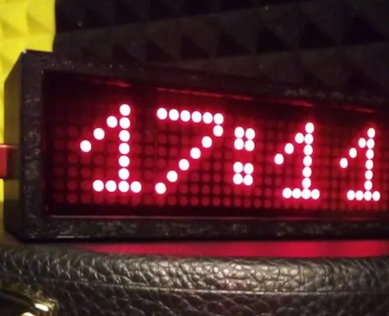
There are almost endless variations of clocks for sale on the internet today, but it is still easy to end up in a situation where you can’t quite find a model with the style and features you want. Marco Zonca ended up with that problem while searching for a new clock to put in his music studio. Nothing on the market fit the bill, so he built this minimalist network-updated digital clock.
Zonca wanted a simple design, the ability to adjust brightness, and NTP (Network Time Protocol) updates. There are clocks available with those features, but nothing in the style Zonca wanted. So he created the perfect clock for himself. It displays 24-hour time across a red LED matrix, lets the user control settings like brightness via Bluetooth® Low Energy communication, and always stays in sync with network time.
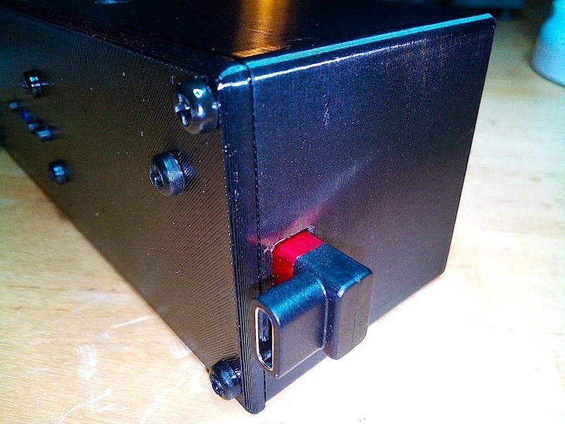
An Arduino Nano ESP32 board, programmed through Arduino Web Editor, controls all of those functions. It mounts onto a custom PCB that Zonca designed for this clock. The PCB also hosts an 8×32 LED matrix display with MAX7219 driver. Three buttons on the PCB let the user select modes. The PCB fits into a black 3D-printed enclosure that reflects the overall minimalist style.
Now Zonca has the perfect clock for his music studio. If you like the look of it, the sketch, PCB files, and 3D enclosure are all available on Hackster.io.
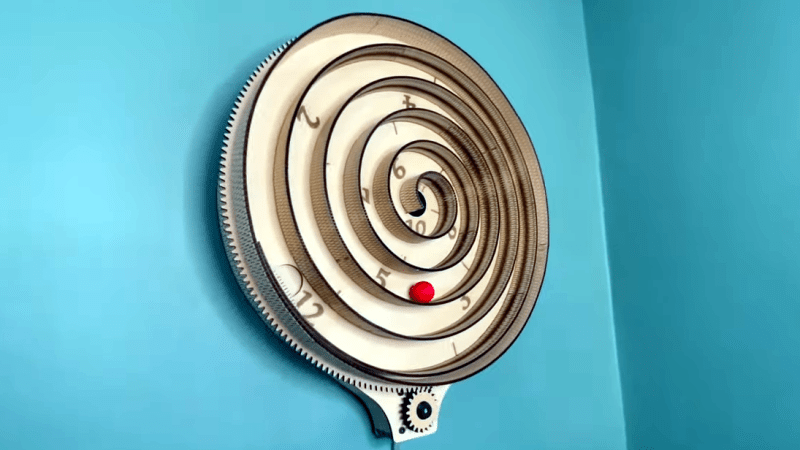
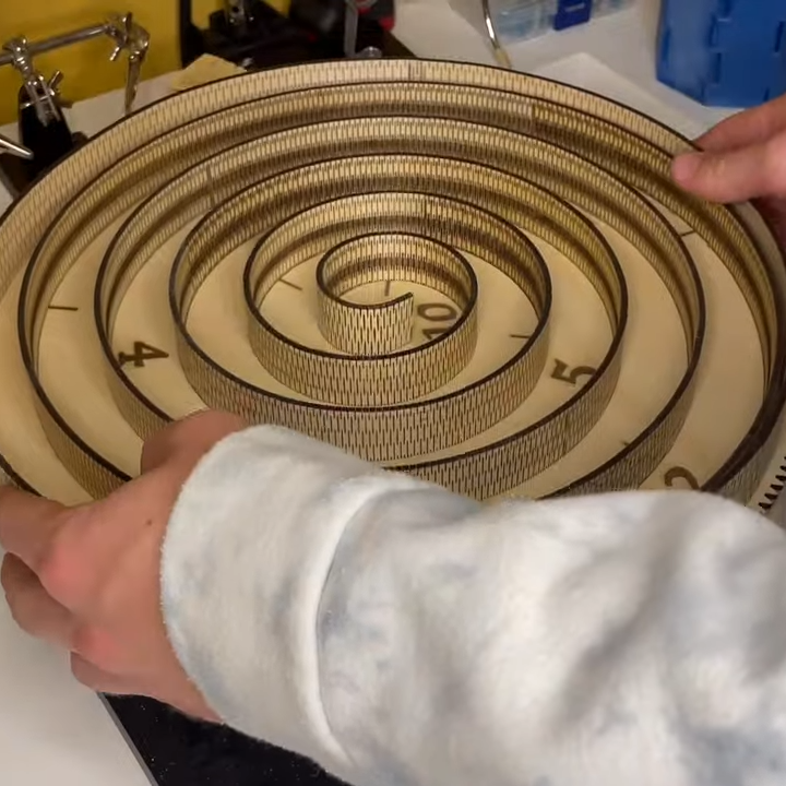
[Build Some Stuff] created an unusual spiral clock that’s almost entirely made from laser-cut wood, even the curved and bendy parts.
The living hinge is one thing, but getting the spacing, gearing, and numbers right also takes work.
The clock works by using a stepper motor and gear to rotate the clock’s face, which consists of a large dial with a spiral structure. Upon this spiral ramp rolls a ball, whose position relative to the printed numbers indicates the time. Each number is an hour, so if the ball is halfway between six and seven, it’s 6:30. At the center of the spiral is a hole, which drops the ball back down to the twelve at the beginning of the spiral so the cycle can repeat.
The video (embedded below) demonstrates the design elements and construction of the clock in greater detail, and of particular interest is how the curved wall of the spiral structure consists of a big living hinge, a way to allow mostly rigid materials to flex far beyond what they are used to. Laser cutting is well-suited to creating living hinges, but it’s a technique applicable to 3D printing, as well.
When Arduino first hit the maker scene, the world of embedded electronics was largely unconnected and offline. But as the IoT, home automation, and smart technology advanced, Arduino kept up. Today, there are a variety of Arduino development boards that offer built-in networking capability and you can use the Arduino Cloud to take advantage of them. To demonstrate that, Doug Domke built this button-free alarm clock.
User interface design is a complex field that has to balance usability, simplicity, and practicality. Take a look at the radio alarm clocks of the 1990s to see how bad user interfaces can make device interaction frustrating. Domke’s alarm clock goes in the complete opposite direction and omits buttons altogether. It lets the user “set it and forget it” through a simple Arduino Cloud dashboard. The time automatically updates based on the configured time zone and daylight savings settings.
This requires very little hardware. Power comes in through USB to an Arduino Nano ESP32 board, with a connected piezo buzzer module and four-digit seven-segment display. Those fit inside a basic 3D-printed enclosure. All the magic happens through the Arduino Cloud and Domke explains how to set up an Arduino Cloud account, create a dashboard, and connect the Nano ESP32 to that dashboard.
If you want a dedicated alarm clock, this is a quick and easy project that will help you get acquainted with the Arduino Cloud for future IoT projects.
It’s back to school! Whether you are a student or not, Arduino’s Project Hub is a great place to never stop learning, thanks to the wealth of knowledge, experiments, and plain cool ideas our community so generously shares. The three highlights we’ve selected among the projects uploaded in June indeed all have something to teach us… with one valuable lesson in common: the past has a lot to offer, if we take the time to recharge, rediscover or revamp it just a little!
This tutorial is so clear it can make anyone feel capable of building their own charger – with additional functionalities such as determining battery wear. Batteries always have to be handled with care, but if you have the skills to customize code and solder a circuit according to the schematic provided, more power to you! All you need are an Arduino Nano and a few other common components.
This is not just a project, but a wonderful deep-dive on wireless communication where you’ll learn about the ISM band, ASK modulation, and synchronous and asynchronous demodulation. More importantly, you might rediscover the “simpler and older radio frequency devices and schemes” that are perfect to save resources on smaller projects. In this case, they will be all you need to implement wireless communication interfacing a Nano with a 433 MHz RF module.
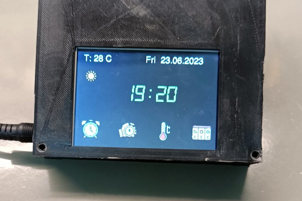
Time and date, timer and alarm, but also detailed temperature data and even the weather forecast: you can have it all in one clock! With this project, Project Hub user dzh121 improved upon a previous version of theirs by adding a touchscreen and displaying more information. An impressive device that makes great use of Arduino IoT Cloud-based dashboards.
For your chance to be selected for a $100, $300 or even $500 gift card to spend on the Arduino Store, submit your best project on the Project Hub! We will be awarding three new entries every month, as detailed in the complete terms and conditions. Good luck!
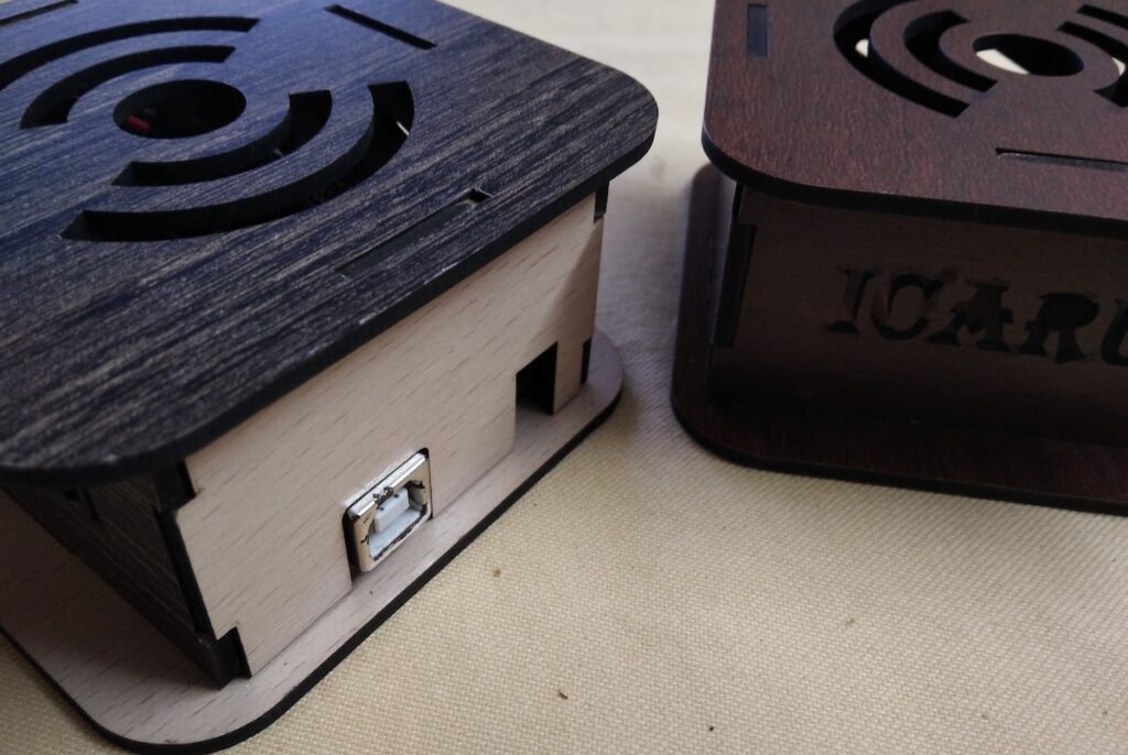
In retrocomputing circles, it’s often the case that the weirder and rarer the machine, the more likely it is to attract attention. And machines don’t get much weirder than the DEC Rainbow 100-B, sporting as it does both Z80 and 8088 microprocessors and usable as either a VT100 terminal or as a PC with either CP/M or MS-DOS. But hey — at least it got the plain beige box look right.
Weird or not, all computers have at least a few things in common, a fact which helped [Dr. Joshua Reichard] home in on the problem with a Rainbow that was dead on arrival. After a full recapping — a prudent move given the four decades since the machine was manufactured — the machine failed to show any signs of life. The usual low-hanging diagnostic fruit didn’t provide much help, as both the Z80 and 8088 CPUs seemed to be fine. It was then that [Joshua] decided to look at the heartbeat of the machine — the 24-ish MHz clock shared between the two processors — and found that it was flatlined.
Unwilling to wait for a replacement, [Joshua] cobbled together a temporary clock from an Arduino Uno and an Si5351 clock generator. He connected the output of the card to the main board, whipped up a little code to generate the right frequency, and the nearly departed machine sprang back to life. [Dr. Reichard] characterizes this as a “defibrillation” of the Rainbow, and while one hates to argue with a doctor — OK, that’s a lie; we push back on doctors all the time — we’d say the closer medical analogy is that of fitting a temporary pacemaker while waiting for a suitable donor for a transplant.
This is the second recent appearance of the Rainbow on these pages — [David] over at Usagi Electric has been working on the graphics on his Rainbow lately.
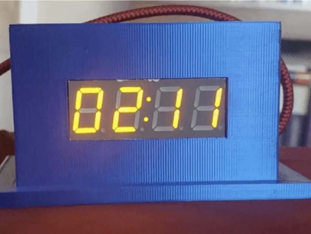
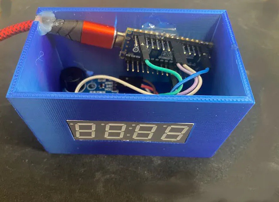
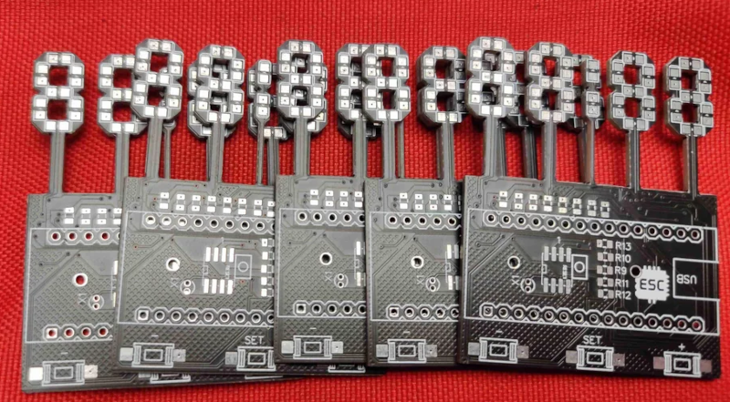
Of course, there’s nothing unusual about using 7-segment displays, especially in a clock. However, [Edison Science Corner] didn’t buy displays. Instead, he fabricated them from a PCB using 0805 LEDs for the segments. You can see the resulting clock project in the video below.
While the idea is good, we might have been tempted to use a pair of LEDs for each segment or used a diffuser to blur the LEDs. The bare look is nice, but it can make reading some numerals slightly confusing.
The remainder of the project is what you’d expect, a 3D-printed case and an Arduino Nano coupled with a DS1307 make the clock part work.
Honestly, with a few changes, we’d like to make up some of these boards for other kinds of custom displays. We can imagine a PCB where the bottoms of the display elements are right at the edge of the board instead of on stalks. You could even create a 14-segment display (we used to call these British flag displays) to make custom text messages. Of course, you can also make custom electroluminescent displays on a PCB reasonably easily, too.
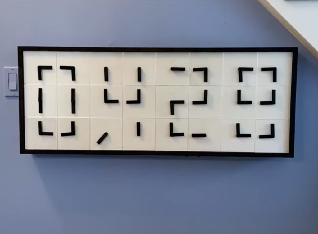
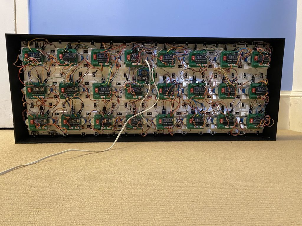
Clocks are fantastic means of creative expression, as they serve a practical purpose and therefore have a reason to exist, but aren’t limited to pure functionality. As such, we see many interesting clock designs. But ihart’s 3D-printed digital clock made from 24 individual analog clocks takes the proverbial cake.
When observed from a distance, this clock looks like it contains large seven-segment displays. But it actually displays the numerical digits of the time using the two hands of 24 individual analog clocks. Those analog clocks don’t show the time, but instead form the segments that make up the “digital” digits. The choreographed dance of the clock hands as the time changes is mesmerizing and the sheer complexity of the system should excite even the most stoic engineers in our audience.
Each of the 24 analog clocks has two hands that move independently, so this clock requires a total of 48 stepper motors. Each hand also requires a Hall effect sensor for finding its home position. While there were many other potential solutions, ihart chose to use one Arduino Nano board for every analog clock. That means that each Arduino controls two stepper motors. To simplify wiring and power distribution, ihart designed a custom PCB to host each of those 24 Arduino boards. A 25th Arduino Nano, paired with an RTC (real-time clock) module, coordinates the operation of the other 24.
All of the mechanical components of the clock were 3D-printed. The design is somewhat modular to keep the unique part count down, which means that this could be expanded into a larger display. But even as it is, the clock is very impressive.
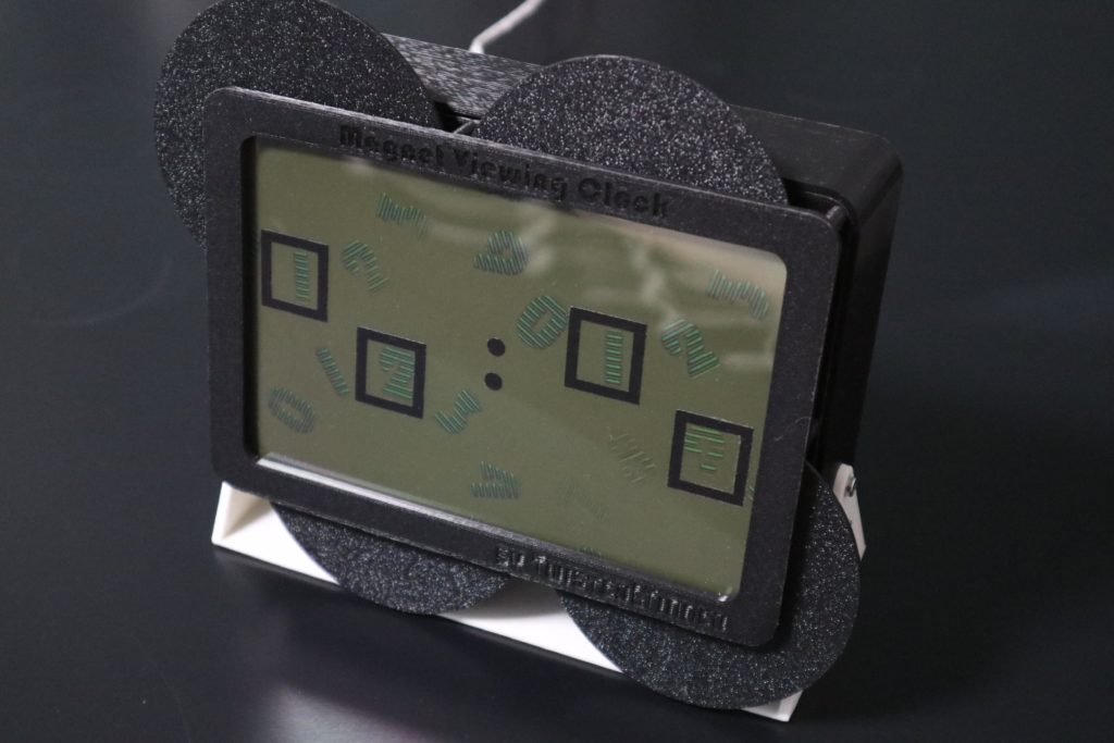
You’ve probably seen videos of people moving magnets near iron dust, which results in the dust aligning itself to the patterns created by the magnetic fields. Magnetic viewing film works the same way, but with the dust in an oil suspension sitting in the gap between two sheets of transparent plastic. By moving that film over magnets, one can see the magnetic fields almost like they’re on an LCD panel. Mosivers took advantage of that fact to build a clock that displays the time on magnetic viewing film.
Mosivers did this by putting a small sheet of magnetic viewing film in a 3D-printed frame over four wheels. They arranged numbers around the circumference of those four wheels, a bit like an analog clock face. The numbers are made of magnetic foil, so their magnetic fields appear on the viewing film as the wheels rotate. Four boxes stenciled onto the viewing film indicate which numbers make up the current time, so reading this magnet clock is as easy as any digital clock.
Each of the four wheels has its own pancake-style stepper motor. An Arduino Uno board controls those motors through a CNC Shield outfitted with stepper drivers. The Arduino keeps track of the current time using a DS3231 real-time clock (RTC) module. For now, the user must manually set the zero position of each wheel each time they turn the clock on, but Mosivers plans to add Hall-effect sensors soon to automate that process. The numbers are a little faint due to the weak magnetic fields produced by the foil, but are still completely readable.
For those unfamiliar with the details of the expansive work of fiction of Harry Potter, it did introduce a few ideas that have really stuck in the collective conscious. Besides containing one of the few instances of time travel done properly and introducing a fairly comprehensive magical physics system, the one thing specifically that seems to have had the most impact around here is the Weasley family clock, which shows the location of several of the characters. We’ve seen these built before in non-magical ways, but this latest build seeks to drop the price tag on one substantially.
To do this, the build relies on several low-cost cloud computing solutions and smartphone apps to solve the location-finding problem. The app is called OwnTracks and is an open-source location tracker which can report data to any of a number of services. [Simon] sends the MQTT data to a cloud-based solution called HiveMQCloud, but you could send it anywhere in principle. With the location tracking handled, he turns to some very low-cost Arduinos to control the stepper motors which point the clock hands to the correct locations on the face.
While the build does rely on a 3D printer for some of the internal workings of the clock, this does bring the cost down substantially when compared to other options. Especially when compared to this Weasley family clock which was built into a much larger piece of timekeeping equipment, having an option for a lower-cost location-tracking clock face like this one is certainly welcome.
Analog panel meters (APM) are instruments that measure and display variables on a dial, usually with a moving pointer or needle in front of a proportional scale.
I wanted to try using these meters in a clock project but have been put off by their high unit cost. However, a recent ‘fire sale’ at a local electronics wholesaler provided the opportunity to acquire 10 meters for just a few cents each, so this project became feasible.
All the files and software for this project are available online at my code repository.
The concept for this clock is to display the clock’s date and time elements on a number of separate meters, each driven by the voltage produced by the microcontroller analog output.
Analog Panel Meters
Panel meters are simple electromechanical devices that can be used to measure currents, voltages, and resistances.
The basic part of any meter is the movement (a moving coil with associate mechanical pivots and adjusters). The movement moves the needle over the calibrated range to indicate the quantity being measured.
The coil works as a simple electromagnet – if you apply a voltage to the coil and a current flows through it, it magnetizes its iron core and creates a magnetic field that moves the pointer in proportion to the voltage applied. A spring holds tension on the movement to balance the electromagnetic force and return it to the zero position when no voltage is applied.
A good video of how meters work can be found here.
The panels meters I purchased (Jaycar QP5020) are designed to measure a full-scale deflection of 20V DC, but the maximum analog output from the microcontroller is 5V, so something needed to be modified.
Meter Recalibration
Most panel meters are just a raw movement, with a certain sensitivity, often written on the lower portion of the scale. Typical wording would be “10 mA FS” to indicate that the meter needs a 10mA current through it for full scale deflection. This full scale current usually has no relation to the indicator scale markings.
To recalibrate the meter you need to adapt the resistance of the driving circuitry to achieve the full scale current of the panel meter with the new driving voltage. You can see in the photo below that, for the volt meter used in this project, there was an internal resistor in series with the + terminal used to calibrate the meter.
Panel Meter Internals
For the as-purchased full scale range (1mA from the meter specs), the 20V reading was achieved with a 20kΩ resistor in series with the measured voltage. By Ohms Law (I=V/R) this gives a full scale current of (20V/20kΩ) = 1mA. So, reversing the calculation, to show a full scale voltage of 5V – the maximum Arduino analog output – we need to replace the resistor with a (5V/1mA) = 5kΩ resistor.
Changing Meter’s Faceplate
Once the range is changed the original panel meter indicator scale becomes obsolete, so it needs a new faceplate. In any case I wanted to show time and date values, not voltages, so I went searching for software that could help with this task.
Original Faceplate
I found 2 commonly referenced/recommended specialist tools that run under Microsoft Windows:
Meter (link here) has a paid and free version. The free MeterBasic (a cut down version of the paid version) is sufficient for a hobbyist who needs to generate the occasional simple scale. It is based on a subset of the features found in Meter and has no time or usage limitations. The design of the scale/faceplate is based on input entered into fixed parameter fields, with a draft displayed in the application window before printing it out.
Galva (link here) is a free program that was specifically designed to draw precise dials for galvanometers, potentiometer, CVs, and other dial-type devices, although it is now more general. It can draw scales with all kinds of shapes (curved or straight) and graduations (linear, functions of a power, logarithmic, specific, manual, etc.). Scales are produced using a scripting language with an on-screen graphical preview before printing.
After experimenting with both I decided to use Galva. The learning curve was much steeper but it seemed to be more flexible and the output looker cleaner on my printer. The script used to produce the scales shown below is included within in the project sketch source folders.
New Faceplate
MCU Analog Output
On thing to note is that the MCU ‘analog’ output is really a PWM output, which means that the meter is not measuring a constant voltage but an oscillating square wave.
I ran some tests with the meters used in this project and they did not seem to be affected by this (ie, setting the voltage to a known value showed the approriate proportional movement of the meter dial). However, this may not be the case for other meters and will need to be determined on a case by case basis. The solution would be to smooth out the voltage with a capacitor – lots on material on the internet for this.
It is also worth noting that USB power supplies are not usually exactly 5V and therefore the MCU output cannot be exact, creating errors in the full scale deflection of the meter. There are a couple of easy solutions for this:
Ensure that the voltage is correct. My experience is that a USB power supply is usually just under 5V, so this is the option I used. By adding by adding in a step-up buck converter at the USB power input to the clock, I ensure that the voltage remains at exactly 5V for ll the clock circuits. This makes the internal voltage independent of the supply voltage as long as it is 5V or less. If your usual supply is greater that 5V then a step-down buck converter could be used to the same effect.
Match the internal resistance to the expected voltage (eg, use an adjustable variable resistor instead of a fixed value). This works well for an arbitrary voltage but only for that specific voltage. Should the voltage fluctuate it will stop working and need readjusting.
System Hardware
Once I was sure that the concept was valid, it was time to consider the system architecture.
System Block Diagram
The clock is powered through a USB power-only socket. A step-up voltage converter is used to maintain the calibrated, accurate, constant 5V for the clock circuits.
The RTC time clock is a DS3231 module with an I²C interface. The APM displays month, date, day of week, hours and minutes on the meter dials APM1 through APM55.
Finally, two momentarily-on switches (for Mode and Set) are used for setting and displaying the time.
The hardware was prototyped using my existing prototyping modules (see this previous blog post) modules and an Arduino Uno, shown below.
APM Clock prototype
Clock Case
Front Panel and Enclosure
For this project the case is made from three parts – a perspex front panel, plywood sides and a removable plywood back.
The perspex front panel was drawn in Fusion360 to produce a 1:1 paper template that allowed me to easily drill out the holes for the APMs. This does not need to be too neat as the holes are hidden behind the APM faces and the outside edges are covered by the enclosure face frame when installed.
The inside of the transparent perspex panel was sanded and spray painted black to produce the effect shown in the photos below.
The sides are a simple 12mm plywood box with a mitred face frame. The perspex panel was butted to the inside of the face frame and fixed in place with a bead of hot glue around the inside edge join in the box.
The back (not shown) is 3mm plywood attached with M3 machine screws into threaded inserts installed on the edge of the plywood box. The back has a cut out to install the USB connector and two tact switches.
Switches and Power Connection
A 3D printed part was produced as a scaffold for the USB connector and Mode/Set switches. This was modelled in Fusion 360, shown below.
The 3D model for this is included in the project files.
Software
To simplify software implementation I used my MD_DS3231 and MD_UISWitch libraries to manage the DS3231 RTC and the switches using the Arduino Pro Mini.
The software for this project is available from my code repository. Essentially it does 4 things:
Periodically update the display. Checks every second and updates when the minutes change.
Manage time setup progression when the mode switch is pressed.
Manage Summer Time offset when the mode switch is long pressed.
Display full range on all APM when the Set switch is pressed.
Display Update
The clock does not show seconds, so the minimum time resolution is 1 minute. The RTC is checked and the display updated every second by counting elapsed milliseconds.
Time Setup
The actual time needs to be input at the start and, from time to time, may need adjusting.
Adjusting the time is started by pressing the Mode switch to move between each APM, the Set switch to increment the value displayed, with roll-around, and the the Mode switch to move on to the next value to be changed. To show which APM is being the ‘current’ value being changed, all the other meter displays are set to zero.
Displays are updated in the order month, date, day of week, hour and minute. As this clock has a 12 hour dial, while the hours are being edited the minute display will move to zero if the hours are in the morning (AM) and move to full scale when the hours are PM.
P:ressing Mode after the last value (minutes) is set will set the time. A one minute inactivity timeout prevents the display from remaining in edit mode indefinitely – the time setting process is aborted and the new time is not set.
Summer Time Offset
Rather than go through the process of setting a new time the Summer Time period, a long press of the mode switch will set up an automatic +1 hour display offset to the RTC time. Summer Time offset is reset to +0 by another long press. The current Summer Time mode is stored in EEPROM and will be retained between power cycles.
Full Range Check
It is useful to occasionally check the full range is accurate. While the clock is displaying the time, pressing the Set switch moves the APM needles to full scale. Releasing the Set switch puts the clock back in normal display mode.
Putting it all together
Once the meters were installed in the enclosure, a ground wire was connected to all the – terminals and a lead to all the + terminals.
The USB and switch module was hot glued to the back panel. The hot glue was also spread over the switch connections to provide some mechanical stability for the wires.
The USB connector and the switch were added to the back panel and wired in. Hot glue was again used to lock the USB socket in place and reinforce the wire connections on the back.
All wires were then soldered to the Pro Mini and it, and the clock module, were hot glued to the base of the enclosure.
The entire was then unit tested before finally closing the case and putting the new clock on the shelf in my office.
Planet Arduino is, or at the moment is wishing to become, an aggregation of public weblogs from around the world written by people who develop, play, think on Arduino platform and his son. The opinions expressed in those weblogs and hence this aggregation are those of the original authors. Entries on this page are owned by their authors. We do not edit, endorse or vouch for the contents of individual posts. For more information about Arduino please visit www.arduino.cc
You are currently browsing the archives for the clock category.


