14
I have a good background working with high voltage, which for me means over 10,000 volts, but I have many gaps when it comes to the lower voltage realm in which RC control boards and H-bridges live. When working on my first real robot, a BB-8 droid, I stumbled when designing a board to convert varying polarities from an RC receiver board into positive voltages only for an Arduino.
Today’s question is, how do you convert a negative voltage into a positive one?
In the end I came up with something that works, but I’m sure there’s a more elegant solution, and perhaps an obvious one to those more skilled in this low voltage realm. What follows is my journey to come up with this board. What I have works, but it still nibbles at my brain and I’d love to see the Hackaday community’s skill and experience applied to this simple yet perplexing design challenge.
The Problem
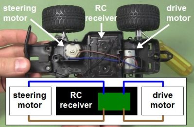
I have an RC receiver that I’ve taken from a toy truck. When it was in the truck, it controlled two DC motors: one for driving backwards and forwards, and the other for steering left and right. That means the motors are told to rotate either clockwise or counterclockwise as needed. To make a DC motor rotate in one direction you connect the two wires one way, and to make it rotate in the other direction you reverse the two wires, or you reverse the polarity. None of the output wires are common inside the RC receiver, something I discovered the hard way as you’ll see below.
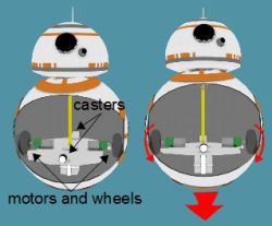
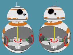
I wasn’t using the RC receiver with the toy truck. I extracted it from the truck and was using it to control my BB-8 droid. My BB-8 droid has two motors configured as what in the BB-8 builders world is called a hamster drive, though is more widely known as a tank drive or differential drive (see the illustrations). Rotate both wheels in the same direction with respect to the droid and the droid moves in that direction. Reverse both wheels and it drives in the opposite direction. Make the wheels rotate in opposite directions and it turns on the spot.

The motors in my BB-8 are drill motors and are controlled by two H-bridge boards. An Arduino does pulse width modulation to the H-bridge boards for speed control, and controls which direction the motors should turn. Finally, the RC receiver is what tells the Arduino what to do. But a converter board, the subject of this article, is needed between the RC receiver and the Arduino. Note that the Arduino is necessary also for countering when the BB-8 droid wobbles and for synchronizing sounds with the movement, but those aren’t addressed here.
Since there are two motors and two directions for each motor, the RC receiver needs to control four pins on the Arduino to make the two drill motors behave as follows: motor 1/clockwise, motor 1/counterclockwise, motor 2/clockwise, motor 2/counterclockwise. And whatever voltages the receiver puts on those pins has to be relative to the Ardunio’s ground.
And herein lies the problem. The Arduino expects positive voltages with respect to its ground on all those pins. So I needed a way to map the RC receiver’s two sets of motor control wires, which can have either positive or negative voltages across them, to the Arduino pins which only want positive voltages. And remember, none of those RC receiver wires are common inside the receiver.
My Fumbling First Approach
Now, keep in mind, electronics is a general interest of mine and except for what we were taught in high school physics class, I’m self-taught. That means I’ve “read ahead” but much of my knowledge has been determined by what projects I’ve done. So I have gaps in my knowledge. I’d never turned negative voltages into positive before. It sounded simple enough. Searching online didn’t help though. The closest I got was in two old posts in forums where the answers were “It’s easy to do. I can do it with a single resistor.” But there was no further explanation and I didn’t ask my own question anywhere at that point.
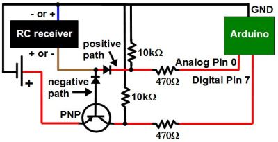
Instead I came up with my own approach with just one set of wires from the RC receiver first. The wires coming from the receiver were blue and brown and could have either polarity depending on which way the receiver is being told to rotate the motor: clockwise or counterclockwise. That meant I needed two diodes to create two possible paths for the different polarities the brown wire could be: positive or negative. I then added a battery for the one path that was negative, to turn it into a positive.
Next, I put a PNP transistor between the positive of the battery and the receiver. With no signal from the RC transmitter, the transistor’s base is negative with respect to the emitter, but not enough to turn the transistor on. That’s because the battery’s negative is connected to the receiver’s blue wire and since there’s no signal from the transmitter, the brown wire is also at the same potential as the blue wire, and with battery negative.
The idea was that when the transmitter sent a signal to make that brown wire negative with respect to the blue wire, it would become even more negative and turn on the PNP transistor. A positive signal would then go from the battery, through the transistor to the Arduino.
The most obvious problem was that the Arduino wanted to see 3 volts to register as a HIGH input, meaning the battery would have to be at least 3 volts and so even with no signal from the transmitter, that would be -3 volts to the transistor, turning it on when it wasn’t supposed to be on.
Using A Relay Instead

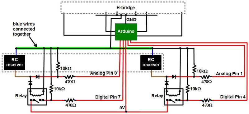
And so I immediately thought of using a relay instead. I’d use the current running through the negative path to energize the relay, closing a switch that was completely independent of the RC receiver. The Arduino has a 5V output pin, so I made that switch close a circuit between the 5V pin and the Arduino’s pin 7, giving pin 7 the needed positive voltage.
The 1 in the circle in the schematic shows where I wanted to put a resistor in order to limit the current going through the relay’s coil. However, I tried with resistors all the way down to 4.7 ohms but the coil didn’t have enough current to close the switch. With no resistor, it worked and the current was 70mA. The relay’s coil was rated for 3V/120mA so I left it.
Using a relay did seem very heavy-handed, but it was the only solution I could come up with and I already had the relay in stock.
The next step was to add a second relay, doing the same for the second set of wires coming from the RC receiver for the second motor.
No Common In The Receiver
But the behavior was seemingly sporadic. And keep in mind that there was a whole dual H-bridge circuit that was also connected to the Arduino’s ground. I’d worked with relays a lot before, and the RC receiver came from a commercially made and functional toy so I had no reason to suspect that. On the other hand, I’d made the H-bridge circuit from scratch since I already had most of the parts, and I was new to H-bridges and MOSFETs. So at first I spent a good two weeks of spare time thinking my problem was with the H-bridge and drill motor side. I’m sure we’ve all experienced the same blindness, thinking the most likely culprit is the part you had a hand in.
But at some point I disconnected the H-bridge and tested just the RC receiver circuit, watching the voltages at the Arduino pins while I remotely turned on both “motors” in both directions in all combinations (no motors were connected at the time though). The only odd behavior I saw was when I turned the motors on in opposite directions.
Notice in the schematic that I’d connected together both blue wires coming from the RC receiver. Up to that point I’d been assuming that the blue wires were common inside the receiver and that it was only the brown wires that switched from positive to negative with respect to the blue wires. From the behavior I was seeing it looked like both wires were switching polarity, possibly around some other internal common reference.
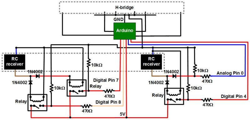
So I added a third relay on one of the positive paths of one of the sets of wires. That meant the corresponding blue wire no longer needed to be grounded, keeping both of the receiver’s blue wires separate. Note that I didn’t bother putting in a fourth relay for the remaining positive path, and it turned out to not be necessary. At that point the circuits worked great and continue to do so.
The Ask
And so I ask, is there a better way to convert the RC receiver output to something the Arduino can use? Relays require power, so it would be nice if there was a solution that didn’t require any extra power. My relay solution seems very early 1900s. Or maybe it’s a good solution after all, but just one of many. Let us know in the comments below.
Filed under: Arduino Hacks, Ask Hackaday