26
Education – the Bipolar Transistor – part two
AC signal, base, BC547, BC548, BC558, bias, collector, darlington pair, education, Electronics, electronics tutorial, emitter, hFE, learning electronics, NPN, PNP, saturated, saturation, transistor, transistor amplifier, tronixstuff Comments Off on Education – the Bipolar Transistor – part two
Hello readers
Today we continue with the second in a series of articles about the bipolar transistor. The first section is here. In this article we look at using the bipolar transistor as an amplifier. That is, change a very small alternating-current signal and make it larger, increasing the amplitude of the signal. Although originally it would seem to be rather simple, perhaps it is not. There are many, many ways to construct a transistor amplifier circuit, but I hope this introduction helps your basic understanding of the process.
When we used the transistor as a switch in part one, we were concerned about the amount of current that flowed between the base and the emitter – that it did not exceed the maximum rating for the particular transistor. When a transistor is allowing the most amount possible of current to flow, it is saturated – the point where the transistor cannot handle any more current. However, to use a transistor as an amplifier we need to bias the transistor so that it is passing current, but not saturated. The procedure of setting the output DC level is known as biasing. The procedure for biasing is outside the scope of this article, as there are many ways of constu
When selecting transistors one needs to take note of the hFE (DC current gain), as variations in this will require a complete recalculation of the values for the bias resistors. Even a common model such as the BC548 is available with hFE ranges between 110~520.

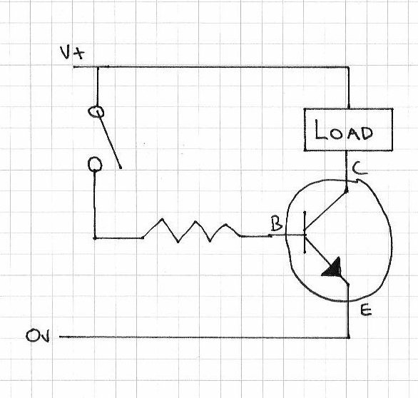
one transistor amplifier
Consider the example schematic above. The transistor is not saturated, due to the bias being set by the two 10k ohm resistors, which drops the voltage over the base by around half. In this case with our 6V supply this drops to around 3V. When power is applied, the transistor is biased and allows a small amount of current to flow, but it still has a lot more current-handling capacity. In testing this example, without an input the base current Ib is 0.32 milliamps, and the collector current Ic is 19.9 milliamps . These amounts of current are known as the quiescent current values.
The purpose of the 0.1 uF capacitor is to block DC current and only allow AC current to flow. When the AC current passes through the 0.1 uF capacitor, it is combined with the DC quiescent current running through the base and rides the stronger current out of the emitter. At which point the 100 uF capacitor before the speaker stops the DC current and only allows the AC signal through to the speaker, but amplified. The level of amplification is dependent upon the gain of the transistor, and the amount of base current. Let’s have a look at the behaviour of the current as it passes through the example circuit above:
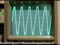
At the end stage of the video clip we increased the input signal greatly. Did you notice the clipping at the output? This occurs when the voltage is too great for the transistor, and therefore it cannot pass the complete signal through to the emitter. In an audio signal situation, this will cause distortion. That is another reason to check the specification of the transistor against your requirements.
Moving along. You can also connect more than one transistor together to increase the amplification, for example:
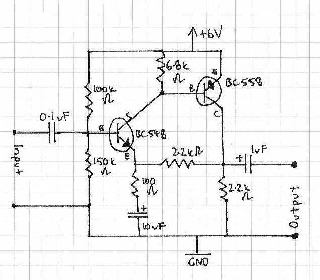
two-transistor amplifier
The left half of the circuit above should be familiar. The 10uF capacitor at the bottom is to stop the DC current being passed through to the base of the BC548 transistor. The second transistor, the BC558 is a PNP transistor, and amplifies the signal at the collector of the BC548. Finally, the 1uF capacitor blocks the DC current from reaching the output. However in using two or more transistors in such a method, you need to ensure the emitter current rating of the second transistor is much higher, as the gain of two transistors is the product of the individual transistors’ gain.
Question – Who makes the BC547 transistors sold by Little Bird Electronics?
![]()
As stated at the beginning, this is only an introduction. There are literally hundreds of thousands of pages of material written about the use of transistors, so don’t stop here – experiment and do your own research and learning!
As always, thank you for reading and I look forward to your comments and so on. Furthermore, don’t be shy in pointing out errors or places that could use improvement. Please subscribe using one of the methods at the top-right of this web page to receive updates on new posts. Or join our new Google Group.
Otherwise, have fun, be good to each other – and make something! ![]()