Posts | Comments

Planet Arduino

Archive for the ‘transistor’ Category

A Super Nintendo that has trouble showing sprites doesn’t make for a very good game system. As it turns out, Super Mario World is a lot less fun when the titular hero is invisible. So it’s no surprise that [jwotto] ended up tossing this partially functional SNES into the parts bin a few years back.

But he recently came up with a project that may actually benefit from its unusual graphical issues; turning the glitched console into a circuit bent video synthesizer. The system was already displaying corrupted visuals, so [jwotto] figured he’d just help things along by poking around inside and identifying pins that created interesting visual effects when shorted out.

Installing the new electronics into the SNES.

Once he mapped out the pins, he wired them all up to a transistor switching board that he’d come up with for a previous project. That would let an Arduino short out the pins on command while still keeping the microcontroller relatively isolated from the SNES. Then it was just a matter of writing some code that would fire off the transistors based on MIDI input.

The end result is a SNES that creates visual glitches along with the music, which [jwotto] can hook up to a projector when he does live shows. A particularly neat feature is that each game responds in its own way, so he can swap out the cartridge to show completely different visuals without having to change any of the MIDI sequencing.

A project like this serves as a nice introduction to both circuit bending and MIDI hacking for anyone looking to get their digital feet wet, and should pair nicely with the MIDI Game Boy Advance.

[Thanks to Irregular Shed for the tip.]

Oct
06

Flashing a Nixie with an Arduino

arduino, clock, high voltage, IN-3, MJE340, nixie, transistor Comments Off on Flashing a Nixie with an Arduino 

nixie-600x398

Kevin Rye writes:

I’m in the very early stages of prototyping a nixie clock. I picked up some MJE340 power transistors to switch on some IN-3s. I can then use a digital pin on my Arduino to turn on the IN-3s through the transistor. I’ll then have myself a blinking colon for my nixie tube clock.

[via]

Flashing a Nixie with an Arduino - [Link]

screen-shot-2014-02-28-at-4-31-47-pmRaspberry Pi and Raspberry Pi Alamode join forces to control a Pinewood Derby race track.

Read more on MAKE

Nov
23
8210567925What happens when you want to play two instruments at the same time, but only have two hands? You let electronics do the work for you, of course.

Read the full article on MAKE

I have recently received the following question from a reader: I’m looking for a circuit board design that will need to turn on an array of LEDs when motion is detected during the day time, and also stay on continuously during the night time; using the Arduino would be nice. The project that I am […]

The post Motion and Light Sensors with Arduino (and Without) appeared first on Tinker Hobby.

Hello readers

Today we continue with the second in a series of articles about the bipolar transistor. The first section is here. In this article we look at using the bipolar transistor as an amplifier. That is, change a very small alternating-current signal and make it larger, increasing the amplitude of the signal. Although originally it would seem to be rather simple, perhaps it is not. There are many, many ways to construct a transistor amplifier circuit, but I hope this introduction helps your basic understanding of the process.

When we used the transistor as a switch in part one, we were concerned about the amount of current that flowed between the base and the emitter – that it did not exceed the maximum rating for the particular transistor. When a transistor is allowing the most amount possible of current to flow, it is saturated – the point where the transistor cannot handle any more current. However, to use a transistor as an amplifier we need to bias the transistor so that it is passing current, but not saturated. The procedure of setting the output DC level is known as biasing. The procedure for biasing is outside the scope of this article, as there are many ways of constu

When selecting transistors one needs to take note of the hFE (DC current gain), as variations in this will require a complete recalculation of the values for the bias resistors. Even a common model such as the BC548 is available with hFE ranges between 110~520.

one transistor amplifier

Consider the example schematic above. The transistor is not saturated, due to the bias being set by the two 10k ohm resistors, which drops the voltage over the base by around half. In this case with our 6V supply this drops to around 3V. When power is applied, the transistor is biased and allows a small amount of current to flow, but it still has a lot more current-handling capacity. In testing this example, without an input the base current Ib is 0.32 milliamps, and the collector current Ic is 19.9 milliamps . These amounts of current are known as the quiescent current values.

The purpose of the 0.1 uF capacitor is to block DC current and only allow AC current to flow. When the AC current passes through the 0.1 uF capacitor, it is combined with the DC quiescent current running through the base and rides the stronger current out of the emitter. At which point the 100 uF capacitor before the speaker stops the DC current and only allows the AC signal through to the speaker, but amplified. The level of amplification is dependent upon the gain of the transistor, and the amount of base current. Let’s have a look at the behaviour of the current as it passes through the example circuit above:

At the end stage of the video clip we increased the input signal greatly. Did you notice the clipping at the output? This occurs when the voltage is too great for the transistor, and therefore it cannot pass the complete signal through to the emitter. In an audio signal situation, this will cause distortion. That is another reason to check the specification of the transistor against your requirements.

Moving along. You can also connect more than one transistor together to increase the amplification, for example:

two-transistor amplifier

The left half of the circuit above should be familiar. The 10uF capacitor at the bottom is to stop the DC current being passed through to the base of the BC548 transistor. The second transistor, the BC558 is a PNP transistor, and amplifies the signal at the collector of the BC548. Finally, the 1uF capacitor blocks the DC current from reaching the output. However in using two or more transistors in such a method, you need to ensure the emitter current rating of the second transistor is much higher, as the gain of two transistors is the product of the individual transistors’ gain.

Question – Who makes the BC547 transistors sold by Little Bird Electronics?

As stated at the beginning, this is only an introduction. There are literally hundreds of thousands of pages of material written about the use of transistors, so don’t stop here – experiment and do your own research and learning!

As always, thank you for reading and I look forward to your comments and so on. Furthermore, don’t be shy in pointing out errors or places that could use improvement. Please subscribe using one of the methods at the top-right of this web page to receive updates on new posts. Or join our new Google Group.

Otherwise, have fun, be good to each other – and make something! :)


Jul
20

Arduino Motor Control for the Spinning Night Light | Part 3

arduino, circuit, diode, motor, project, spinning night light, transistor Comments Off on Arduino Motor Control for the Spinning Night Light | Part 3 

Simple motor controlMost motor control applications can be accomplished with a simple single-transistor circuit. This type of circuit controls the basic operation of turning the motor on and off, and allows very fast switching of the motor, which makes it possible to control the speed of the motor using pulse width modulation (PWM).

The basic problem with this circuit is that the direction of the motor cannot be reversed. For our simple application in this RGB LED night light, spinning the motor in one direction is enough. In the future we will use motors in applications which require us to reverse the direction as well, and for that we will be using the type of motor control circuit called H-bridge circuit.

Note that a diode has been used in this circuit. The core of all types of motors is the inductor (or coil). When the amount of current (which can be moderate to high) passing through the inductor is changed, it produces large voltage spikes (“kickback” ) .

The diode used in motor control circuits is called a kickback diode and its purpose is to absorb the voltage that is produced when the transistor is turned on and off. When you are developing motor control applications using a bipolar transistor you should always put in the kickback diode in order to protect the other parts of your circuit.

Here’s the sketch for the spinning night light.

Arduino Motor Control for the Spinning Night Light | Part 3 originally appeared on Tinker Hobby on July 20, 2010.

Jun
07

Electronic components – the Bipolar Transistor as a switch

BC548, bipolar, BJT, education, FET, learning electronics, NPN, PNP, transistor, tronixstuff Comments Off on Electronic components – the Bipolar Transistor as a switch 

Hello readers

Today we continue with the series of articles on basic electronics with this introductory article about the bipolar transistor, and using it as a switch.

What is a transistor?  It is a semiconductor with three leads, with which a small voltage or current applied to one lead can control a much larger current flowing through the other two leads. A transistor can be used as either a switch or an amplifier. Furthermore, there are two main types of transistor – the bipolar and the field-effect transistor. This article will examine and refer to bipolar transistors as transistors. Let’s go!

A transistor consists of three layers of silicon, P- and N-type in fact. Do you recall the diode article? A transistor is basically two diodes connected together in a Y-formation, in one of two ways as shown below:


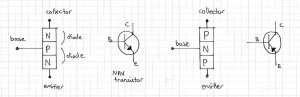
Also notice the circuit symbols for NPN and PNP-type transistors. Transistors can be found in many shapes and sizes, the size usually being directly proportional to the amount of current the particular transistor is designed to handle. Thankfully the physical shape or package design has been standardised, and each casing type has a designation. Let’s look at some of the more common ones now:

TO-92 casing. When the flat-side is facing you, the pin numbering is 1-2-3. This casing style is for transistors that usually handle up to 100 mA. Unfortunately there are three varieties with regards to which pin is the base, collector and emitter – so always check your data sheet if in doubt.

TO-220 casing. When the metal tab is at the rear (above), the pin numbering is 1-2-3. The metal tab acts as a heatsink, and the hole enables one to bolt it to a larger heatsink, metal chassis, etc. This casing style is for transistors that usually handle up to around 8 amps.

TO-3 casing. These are all metal in order to dissipate heat – as they can handle up to around 75 amps of current. The entire metal case and ends are pin 2; pins 1 and 3 are the usual leads. Check your data sheet for pins 1 and 3! There are many other types of casing, but the three above are usually the most common.

How do transistors work?

For current to flow from the base of a transistor to the emitter, it needs to be forward-biased by at least 0.6 volts. In other words, there must be a potential difference between the base and emitter by 0.6V. If the base is connected to ground, the transistor will not let current pass from the collector to the emitter.

The transistors in the circuits above are NPN transistors. The current that flows from the base to the emitter is known as base current or Ib. The current that flows from the collector to the emitter is known as the collector current, or Ic. An interesting property of the transistor is this: the ratio of Ic to Ib is constant, and Ic is always larger than Ib. The ratio of Ic/Ib is known as the gain of the transistor. When reading a data sheet, gain is usually defined as hFE. This formula also proves that if there is no base current, there will be no collector current – you can’t divide by zero.

Using the transistor as a switch

To use a transistor as a switch, we need to know several things to be successful. For example:

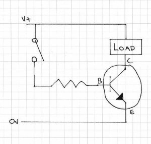
To use the transistor to turn on the “load” we need to:

  • know the current drawn by the load. This is also the transistor’s Ic (collector current). Or the load’s resistance, as Ohm’s law can be used to calculate the current
  • know the transistor gain (hFE)
  • calculate Ib (base current)
  • use the above data to find a value for that lonely resistor

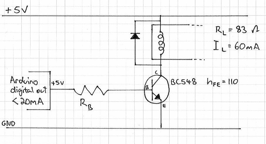
Let’s do that now with a contemporary problem… we have an Arduino that needs to turn a relay on and off at certain times. However you can only source up to 20 mA from a digital output on the Arduino, so we want to use it instead to switch a transistor which can control the relay coil. The problem is, what value resistor to use to control the base current?

First of all, let’s note what we do know. The relay (data sheet) coil requires 60 mA of current to activate, it is a 5 volt relay, and the coil has a resistance of 83 ohms. The transistor (data sheet) is a BC548 NPN transistor, very cheap and easy to find. It can handle a collector/load current of 100 mA, and the hFE (gain) is 110.  That diode is there to loop back pulse current when the relay is switched off. The supply voltage is 5 volts, and the digital output from the arduino is also 5 volts when active. There is also one more thing to take note of – the base-emitter junction is a diode, and therefore has a voltage drop of 0.7 volts. When you are switching large voltages, this is not an issue – however as we are working with a small voltage, the drop needs to be taken into account.

So, let’s calculate Ib, the base current. If hFE = Ic/Ib then 110 = 0.06 A/Ib; which translates to Ib = 0.06/110 = 0.0005 A. Which is basically nothing, so we’ll round it up to 1 milliamp.

Next, the resistor value. Using Ohm’s law (voltage = current x resistance):

Voltage = (5-0.7) = 4.3 volts (we need to take into account the voltage drop over the base-emitter junction of the transistor)

Current = 0.005 A (Will use a slightly higher current just to be on the safe side)

So, resistance = 4.3/0.005 = 860 ohms. For such a tiny current and small voltage, a 1/4-watt resistor is fine. (power = volts x current; = 4.3 * 0.005 = 0.0215 < 0.25)

If we didn’t have an 860 ohm resistor, a little higher is OK. I have used a 1k ohm resistor and it has worked nicely.

There you have it, a transistor used as a switch.

As stated at the beginning, this is only an introduction. There are literally hundreds of thousands of pages of material written about the use of transistors, so don’t stop here – experiment and do your own research and learning! In the next few weeks we will look at using transistors as amplifiers.

As always, thank you for reading and I look forward to your comments and so on. Furthermore, don’t be shy in pointing out errors or places that could use improvement. Please subscribe using one of the methods at the top-right of this web page to receive updates on new posts. Or join our new Google Group.

Otherwise, have fun, be good to each other – and make something! :)

Some information for this post is from: historical info from Wikipedia; various technical information and inspiration from books by Forrest Mims III;  TO-3 package photo from Farnell Australia.


  • Newsletter

    Sign up for the PlanetArduino Newsletter, which delivers the most popular articles via e-mail to your inbox every week. Just fill in the information below and submit.

  • Like Us on Facebook