Back in the 486 days, it was common to see a “Turbo” button on the front panel of many PCs, which was used to toggle between the CPU’s maximum speed and a slower clock rate that was sometimes necessary for compatibility with older software. Usually an LED would light up to show you were running at this higher speed, or if you’re machine was very fancy, it might even have a numerical display that would show the current CPU frequency.
[Joshua Woehlke] wanted to add a similar display to his 486, but figured that with modern technology, he could do something a bit more interesting. Especially when he realized that the spot on his case where the two-digit LED display would have originally been mounted was the perfect size to hold a common 0.96″ SSD1306 OLED. From there it was just a matter of wiring it up to an Arduino and writing some code to display different graphics depending on the computer’s current CPU speed.
Just like the frequency indicators of yore, the Arduino doesn’t actually measure the CPU’s frequency, it’s simply reading the state of the Turbo LED on the front panel. When the LED is off the Arduino shows an image of a i8088 CPU on the screen to indicate the computer is running in compatibility mode, and when the LED is on, the screen shows the Cyrix Cx486 DX2 logo. When the button hasn’t been pressed in awhile, the display defaults to a star field screensaver.
Regular readers may recall we recently covered a similar project that used an Arduino to add a little flair to an era appropriate seven-segment LED display. We’d say there’s still a good deal of romanticism about computers having a big “TURBO” button you can smash whenever you feel the need for speed.
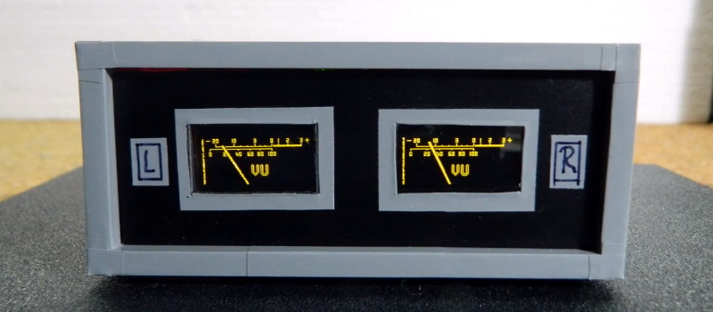
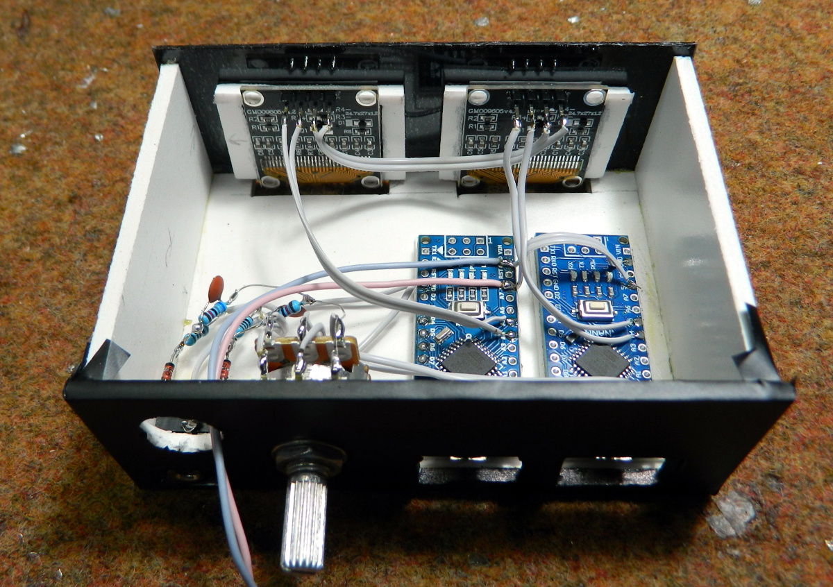
Looking for a digital recreation of the classic analog volume unit (VU) meter? If you’ve got an Arduino, a few passive components, and a SSD1306 OLED, then [mircemk] might have the answer for you. As you can see in the video below, his code turns a handful of cheap parts into an attractive and functional audio display.
The project’s Hackaday.IO page explains that the idea is based on the work of [stevenart], with code adapted for the SSD1306 display and some tweaks made to the circuit. While [mircemk] says the code could be modified for stereo as long as the two displays don’t have conflicting I2C addresses, he decided to simply duplicate the whole setup for each channel to keep things simple. With as cheap as some of these parts are nowadays, it’s hard to blame him.
[mircemk] has provided source code for a couple different styles of VU indicators, the colors of which can easily be inverted depending on your tastes. He also clarifies that the jerky motion of the virtual “needle” seen in the video is due to the camera; in real-life it sweeps smoothly like the genuine article.
With little more than an Arduino, an OLED display, and some buttons, it’s easy to build your own faux-retro game system. There’s even a growing library of titles out there that target this specific combination of hardware, thanks in no small part to the Arduboy project. But unless you’re content to play Circuit Dude on a breadboard, at some point you’ll probably want to wrap the build up in a more convenient form.
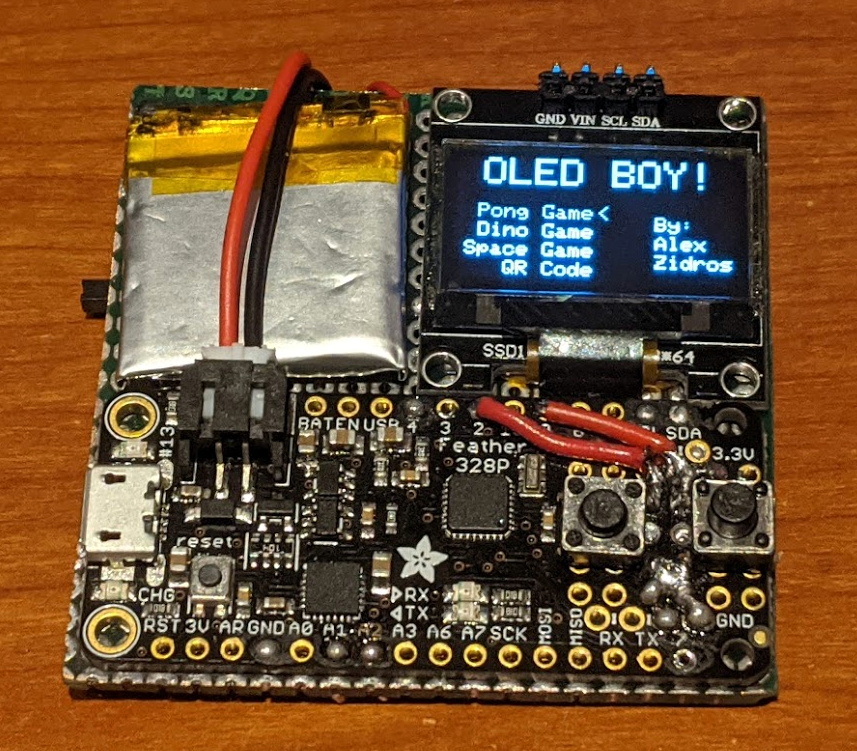
Like many that came before it, the OLED handheld created by [Alex Zidros] takes inspiration from a Nintendo product; but it’s not the Game Boy. Instead, his design is based on a 3D printed grip for the Switch Joy-Cons that he found on Thingiverse. After tacking on a holder for the PCB, he had the makings of a rather unique system.
We especially like the offset SSD1306 OLED display. Not because we think a game system with an asymmetrical layout is a particularly sound design decision, but because it gives the whole build a rather cyberpunk feel. When combined with the exposed electronics, the whole system looks like it could have been cobbled together from a futuristic dumpster. Which is high praise, as far as we’re concerned.
Opposite the display is a LiPo pouch battery that [Alex] says was liberated from a portable speaker, and down below is an Adafruit Feather 328P. There are two tactile switches mounted to the front of the Feather, and in something of a departure from these sort of builds, there are two more on the shoulders of the 3D printed case. Everything is held together with nothing more exotic than a scrap of perfboard, making it easy for anyone who might want to build their own version.
The purpose of this guide is to have an SSD1306-based OLED display successfully operating with your Arduino, so you can move forward and experiment and explore further types of operation with the display.
This includes installing the Arduino library, making a succesful board connection and running a demonstration sketch. So let’s get started!
Connecting the display to your Arduino
The display uses the I2C data bus for communication, and is a 5V and 3.3V-tolerant board.
Arduino Uno to Display
GND ---- GND (GND)

5V/3.3V- Vcc (power supply, can be 3.3V or 5V)

A5 ----- SCL (I2C bus clock)

A4 ----- SDA (I2C bus data)
I2C pinouts vary for other boards. Arduino Leonard uses D2/D3 for SDA and SCL or the separate pins to the left of D13. Arduino Mega uses D20/D21 for SDA and SCL. If you can’t find your I2C pins on other boards, ask your display supplier.
Installing the Arduino library
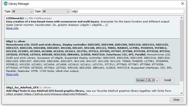
To install the library – simply open the Arduino IDE and select Manage Libraries… from the Tools menu. Enter “u8g2” in the search box, and after a moment it should appear in the results as shown in the image below. Click on the library then click “Install”:
After a moment the library will be installed and you can close that box.
Now it’s time to check everything necessary is working. Open a new sketch in the IDE, then copy and paste the following sketch into the IDE:
// Display > https://pmdway.com/products/0-96-128-64-graphic-oled-displays-i2c-or-spi-various-colors#include<Arduino.h>#include<U8x8lib.h>#ifdefU8X8_HAVE_HW_SPI#include<SPI.h>#endif#ifdefU8X8_HAVE_HW_I2C#include<Wire.h>#endifU8X8_SSD1306_128X64_NONAME_HW_I2Cu8x8(/* reset=*/U8X8_PIN_NONE);/* This example will probably not work with the SSD1606, because of the internal buffer swapping*/voidsetup(void){/* U8g2 Project: KS0108 Test Board *///pinMode(16, OUTPUT);//digitalWrite(16, 0); /* U8g2 Project: Pax Instruments Shield: Enable Backlight *///pinMode(6, OUTPUT);//digitalWrite(6, 0); u8x8.begin();//u8x8.setFlipMode(1);}voidpre(void){u8x8.setFont(u8x8_font_amstrad_cpc_extended_f);u8x8.clear();u8x8.inverse();u8x8.print(" U8x8 Library ");u8x8.setFont(u8x8_font_chroma48medium8_r);u8x8.noInverse();u8x8.setCursor(0,1);}voiddraw_bar(uint8_tc,uint8_tis_inverse){uint8_tr;u8x8.setInverseFont(is_inverse);for(r=0;r<u8x8.getRows();r++){u8x8.setCursor(c,r);u8x8.print(" ");}}voiddraw_ascii_row(uint8_tr,intstart){inta;uint8_tc;for(c=0;c<u8x8.getCols();c++){u8x8.setCursor(c,r);a=start+c;if(a<=255)u8x8.write(a);}}voidloop(void){inti;uint8_tc,r,d;pre();u8x8.print("github.com/");u8x8.setCursor(0,2);u8x8.print("olikraus/u8g2");delay(2000);u8x8.setCursor(0,3);u8x8.print("Tile size:");u8x8.print((int)u8x8.getCols());u8x8.print("x");u8x8.print((int)u8x8.getRows());delay(2000);pre();for(i=19;i>0;i--){u8x8.setCursor(3,2);u8x8.print(i);u8x8.print(" ");delay(150);}draw_bar(0,1);for(c=1;c<u8x8.getCols();c++){draw_bar(c,1);draw_bar(c-1,0);delay(50);}draw_bar(u8x8.getCols()-1,0);pre();u8x8.setFont(u8x8_font_amstrad_cpc_extended_f);for(d=0;d<8;d++){for(r=1;r<u8x8.getRows();r++){draw_ascii_row(r,(r-1+d)*u8x8.getCols()+32);}delay(400);}draw_bar(u8x8.getCols()-1,1);for(c=u8x8.getCols()-1;c>0;c--){draw_bar(c-1,1);draw_bar(c,0);delay(50);}draw_bar(0,0);pre();u8x8.drawString(0,2,"Small");u8x8.draw2x2String(0,5,"Scale Up");delay(3000);pre();u8x8.drawString(0,2,"Small");u8x8.setFont(u8x8_font_px437wyse700b_2x2_r);u8x8.drawString(0,5,"2x2 Font");delay(3000);pre();u8x8.drawString(0,1,"3x6 Font");u8x8.setFont(u8x8_font_inb33_3x6_n);for(i=0;i<100;i++){u8x8.setCursor(0,2);u8x8.print(i);// Arduino Print functiondelay(10);}for(i=0;i<100;i++){u8x8.drawString(0,2,u8x8_u16toa(i,5));// U8g2 Build-In functionsdelay(10);}pre();u8x8.drawString(0,2,"Weather");u8x8.setFont(u8x8_font_open_iconic_weather_4x4);for(c=0;c<6;c++){u8x8.drawGlyph(0,4,'@'+c);delay(300);}pre();u8x8.print("print \\n\n");delay(500);u8x8.println("println");delay(500);u8x8.println("done");delay(1500);pre();u8x8.fillDisplay();for(r=0;r<u8x8.getRows();r++){u8x8.clearLine(r);delay(100);}delay(1000);}
Your display should go through the demonstration of various things as shown in the video below:
If the display did not work – you may need to manually set the I2C bus address. To do this, wire up your OLED then run this sketch (open the serial monitor for results). It’s an I2C scanner tool that will return the I2C bus display.
Then use the following line in void setup():
u8x8.setI2CAddress(address)
Replace u8x8 with your display reference, and address with the I2C bus address (for example. 0x17).
Moving on…
By now you have an idea of what is possible with these great-value displays.
Now your display is connected and working, it’s time to delve deeper into the library and the various modes of operations. There are three, and they are described in the library documentation – click here to review them.
Whenever you use one of the three modes mentioned above, you need to use one of the following constructor lines:
U8G2_SSD1306_128X64_NONAME_F_HW_I2C u8g2(U8G2_R0, /* reset=*/ U8X8_PIN_NONE); // full buffer mode
U8X8_SSD1306_128X64_NONAME_HW_I2C u8x8(/* reset=*/ U8X8_PIN_NONE); // 8x8 character mode
Match the mode you wish to use with one of the constructors above. For example, in the demonstration sketch you ran earlier, we used the 8×8 character mode constructor in line 14.
Where to from here?
Now it’s time for you to explore the library reference guide which explains all the various functions available to create text and graphics on the display, as well as the fonts and so on. These can all be found on the right-hand side of the driver wiki page.
This post brought to you by pmdway.com – everything for makers and electronics enthusiasts, with free delivery worldwide.
To keep up to date with new posts at tronixstuff.com, please subscribe to the mailing list in the box on the right, or follow us on twitter @tronixstuff.
After covering a few of his builds at this point, we think it’s abundantly clear that [Igor Afanasyev] has a keen eye for turning random pieces of antiquated hardware into something that’s equal parts functional and gorgeous. He retains the aspects of the original which give it that unmistakable vintage look, while very slickly integrating modern components and features. His work is getting awfully close to becoming some kind of new art form, but we’re certainly not complaining.
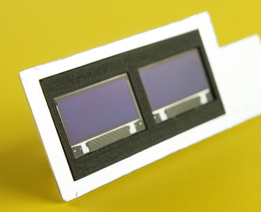
His latest creation takes an old-school “Monopak” electronic flash module and turns it into a desk clock that somehow also manages to look like a vintage television set. The OLED displays glowing behind the original flash diffuser create an awesome visual effect which really sells the whole look; as if the display is some hitherto undiscovered nixie variant.
On the technical side of things, there’s really not much to this particular build. Utilizing two extremely common SSD1306 OLED displays in a 3D printed holder along with an Arduino to drive them, the electronics are quite simple. There’s a rotary encoder on the side to set the time, though it would have been nice to see an RTC module added into the mix for better accuracy. Or perhaps even switch over to the ESP8266 so the clock could update itself from the Internet. But on this build we get the impression [Igor] was more interested in playing with the aesthetics of the final piece than fiddling with the internals, which is hard to argue with when it looks this cool.
Noticing the flash had a sort of classic TV set feel to it, [Igor] took the time to 3D print some detail pieces which really complete the look. The feet on the bottom not only hold the clock at a comfortable viewing angle, but perfectly echo the retro-futuristic look of 50s and 60s consumer electronics. He even went through the trouble of printing a little antenna to fit into the top hot shoe, complete with a metal ring salvaged from a key-chain.
A good deal of the projects we cover here at Hackaday are not, in the strictest sense, practical endeavors. If we required that everything which graced our digital pages had a clear end result, the site would be in a rather sad state of affairs. Sometimes it’s enough just to do something for the challenge of it. But more often than not, you’ll learn something in the process which you can use down the line.
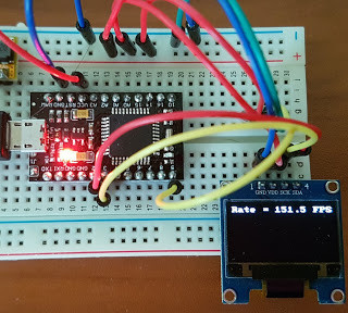
That’s precisely what pushed [Laurence Bank] to see how well he could optimize the frame rate on the popular SSD1306 OLED display. After several iterations of his code, he was able to achieve a blistering 151.5 FPS, with apparently still some room for improvement if he’s feeling up to the challenge. But considering his first attempt was only running at 5.5 FPS, we’d say he’s already more than earned his hacker cred on this one.
A few different tricks were used to achieve such incredible performance gains. To start with, while the official I2C specification says you’re supposed to wait for an acknowledgment back from the device when communicating with it, [Laurence] realized the SSD1306 didn’t actually care. He could continuously blast commands at the display without bothering to wait for an acknowledgment. He admits there are problems with this method, but you can’t argue with the results.
To really wring all the performance out of the system he could, [Laurence] donned his Assembly Cap and examined how the Arduino IDE compiler was interpreting his code. He identified a few areas where changing his C code would force the compiler to generate faster output. He notes that this wouldn’t normally be required when working with more advanced compilers, but that the Arduino toolchain needs its hand held occasionally.
[Lewin] wrote in to tell us about a high speed library for Arduino Due that he helped develop which allows interfacing OLED displays that use the SSD1306 display controller, using DMA routines for faster display refresh time.
Typically, displays such as the Monochrome 1.3″ 128×64 OLED graphic display , are interfaced with an Arduino board via the SPI or I2C bus. The Adafruit_SSD1306 library written by [Limor Fried] makes it simple to use these displays with a variety of Arduinos, using either software or hardware SPI. With standard settings using hardware SPI, calls to display() take about 2ms on the Due.
[Lewin] wanted to make it faster, and the SAM3X8E on the Due seemed like it could deliver. He first did a search to find out if this was already done, but came up blank. He did find [Marek Buriak]’s library for ILI9341-based TFT screens. [Marek] used code from [William Greiman], who developed SD card libraries for the Arduino. [William] had taken advantage of the SAM3X8E’s DMA capabilities to enable faster SD card transfers, and [Marek] then adapted this code to allow faster writes to ILI9341-based screens. All [Lewin] had to do was to find the code that sent a buffer out over SPI using DMA in Marek’s code, and adapt that to the Adafruit library for the SSD1306.
There is a caveat though: using this library will likely cause trouble if you are also using SPI to interface to other hardware, since the regular SPI.h library will no longer work in tandem with [Lewin]’s library. He offers some tips on how to overcome these issues, and would welcome any feedback or testing to help improve the code. The speed improvement is substantial. Up to 4 times quicker using standard SPI clock, or 8 times if you increase SPI clock speed. The code is available on his Github repo.
I needed a display for a project of mine and was just going to use a regular HD44780 -based text LCD display, until I spotted some very neat looking TINY OLED-displays from eBay. The displays are monochrome 128×32 pixel displays with a 4-wire SPI bus and they are around 30x11mm in size (the actual display area is under an inch diagonally!). The exact type of the displays is UG-2832HSWEG04. I found a datasheet for the displays and a datasheet for the actual display controller (SSD1306) and they seemed easy enough to use so I ordered a two of them for just $13.
Using a neat little OLED-display with an Arduino - [Link]
About
Planet Arduino is, or at the moment is wishing to become, an aggregation of public weblogs from around the world written by people who develop, play, think on Arduino platform and his son. The opinions expressed in those weblogs and hence this aggregation are those of the original authors. Entries on this page are owned by their authors. We do not edit, endorse or vouch for the contents of individual posts. For more information about Arduino please visit www.arduino.cc
You are currently browsing the archives for the SSD1306 category.

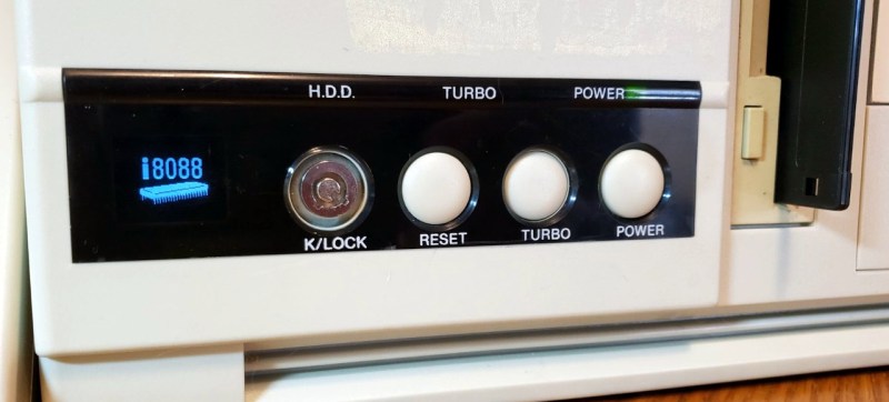
 Just like the frequency indicators of yore, the Arduino doesn’t actually measure the CPU’s frequency, it’s simply reading the state of the Turbo LED on the front panel. When the LED is off the Arduino shows an image of a i8088 CPU on the screen to indicate the computer is running in compatibility mode, and when the LED is on, the screen shows the Cyrix Cx486 DX2 logo. When the button hasn’t been pressed in awhile, the display defaults to a star field screensaver.