
05
Getting Started with Arduino! – Chapter Nine
74HC595, 8x8 matrix, arduino, Arduino Tutorial, education, learning electronics, LED matrix, matrix, microcontrollers, tronixstuff Comments Off on Getting Started with Arduino! – Chapter Nine
This is part of a series titled “Getting Started with Arduino!” by John Boxall – A tutorial on the Arduino microcontrollers, to be read with the book “Getting Started with Arduino” (Massimo Banzi).
The first chapter is here.
Welcome back fellow arduidans!
Just a note: this is the tenth instalment, I hope you have been enjoying the posts, and I sincerely thank you for reading. Let’s go!
This week we will start looking at LED matrix displays, designing user interfaces, implementing a user interface for a clock, and finish up making an alarm clock.
Firstly, let’s have plenty of fun with 64 LEDs! Using an 8×8 LED display module:

Previously we have used 74HC595 shift registers to drive strips of LEDs, single and four-digit LED displays. An LED matrix seems complex at first, but after further investigation quite simple. With sixteen pins you can control 64 LEDs. It works by having 8 row pins, each pin connected to all the anodes on one row; and 8 pins each connected to the cathodes on one column:

It does look like a mess, but we can work it out. As we did with the 4-digit 7-segment display module, we just need one shift register for the anodes, and one for the cathodes. Moving along from exercise 6.2, it will be easy to drive the an LED matrix display – one shift register (the left hand side) will apply current to the rows (anodes) and the other shift register will apply current to NPN transistors to allow current to flow from the cathodes (columns) to ground. So we can make an example quite easily. You will need:
- Your standard Arduino setup (computer, cable, Duemilanove or compatible)
- One 8×8 LED matrix. Try to find one that has LEDs with a forward voltage of 2 volts and a current of less than 20mA. If it is bicolour, that’s ok – just use one colour for now
- Eight 560 ohm 1/4 watt resistors
- Eight 1 kilo ohm 1/4 resistors
- Eight BC548 NPN transistors
- Two 74HC595 shift registers
- Solderless breadboard and connecting wires
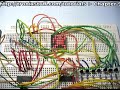
Here is a circuit diagram for our example (click on it to enlarge):

Please note that there are eight transistor/resistor combinations from the second shift register – I just have not drawn them in to save my sanity. They’re on the bottom right of my board:

Now how are we going to light up those LEDs? We need to send two bytes of data to the shift registers, one byte for the row, and one for the column. For this example we will work with individual pixels. For example, say you want to turn on the pixel at 8 across, 8 down – the bottom right. You need to send the following bytes of data to the shift registers: b00000001 and b00000001. In decimal those two numbers are 128 and 128. Or the top-left LED, at 1 across, 1 down – it would be b10000000, b10000000 or decimal 1,1. Once again we can use the functions:
… to send the data to the shift registers. This example sketch for the above circuit should be pretty well self-explanatory if you have been following my tutorials: Example 9.1.pdf.
Here is is in action:
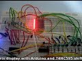
Once again, quite mesmerising. Did you notice that the horizontal solid rows were dimmer than the solid vertical columns? This is because when you light up one row, all eight LEDs are drawing current from one pin of the shift register – so there is less current for each LED; whereas in the column, each LED has its own source of current, so can therefore operate at full brightness. So a hint – when you are creating images or characters for your display, use scrolling columns to display the image.
Experiment with the example 9.1 sketch, if you display only vertical columns, and make the delay zero – you can give the illusion that the entire display is on, but it is not.
Which leads us into the first exercise for the week!
Exercise 9.1
We can display entire columns with our matrix display. We can position these columns on demand. And without a delay, fill up the entire matrix. Now you can create images, or characters and display them on the matrix, one column at a time. For example, the little yellow dude from that popular arcade game many years ago might look like this:

Using the circuit described for example 9.1, create a character, shape, or whatever tickles your fancy, and animate it to move across the screen. To make it easier to calculate the byte values for the columns, I have placed a spreadsheet to use in our Google Group’s file section (matrix-ss.xls or .odt).
Hint – To animate an image, you will need to map the matrix every time the image changes – just like a normal animation or cartoon. However, store all the values for the entire animation in one array, otherwise you will go bonkers. When you need to read the array, each matrix image can be read as they are multiples of eight (then add the reference to the value you want).
For inspiration, here is what I came up with:
and the corresponding exercise 9.1.pdf.
How did you go? If you have an interesting animation, and you can do so – please email a link to Youtube, Vimeo, etc showing your creation – you could win a prize.
Time to get a little more serious now. ![]()
Over time you have been making things, some useful, some more experimental than anything. Hopefully you will reach the stage of designing something that has a real-world use and could be used by people other than yourself or your immediate circle of friends. In the next few weeks we will look at methods of transitioning projects from prototypes to standalone products you can develop!
A major part of your design should be the user interface, or how your project responds to user input and displays data, results and so on. If something is difficult to use, or understand, it will not be a good product. So what can we do about this? This week we will examine the clock made in example 7.4 and change it to be independent of a computer, and easy for the user to operate. But now for some design inspiration…
The humble alarm clock (it has been staring at me every morning). Here is my late grandfather’s clock from the 1960s:


Simple, yet functional. It does what it is supposed to do with the minimum of fuss. (It’s German). And that is how our project user interfaces should be. As technical people it is very easy to get carried away and put buttons, lights, and all sorts of things together, but at the end of the day, less is more. How can we emulate this with Arduino – but in a simple method?
Looking at the face of the clock, it displays the time (hours, minutes, seconds) and the alarm time. We can use an LCD for that. On the top is the alarm off button. We can use a button for that. On the rear there are winders for the time and alarm spring – we have electricity for that. There are two knobs, one to adjust the time, and one to adjust the alarm – here we have several options. We could use up/down buttons… perhaps we could use a knob as well? And finally there is the gain control – we don’t need this as our DS1307 is infinitely more accurate.
A rough map of how you want things to work is always a good start, for example my mess below:

How can this be implemented? Let’s see. The clock will normally display the date, time, etc. If a button is pressed, it will switch to menu mode (on the right). A knob will be used to select one of the options listed on the right, when the required option is displayed, the user presses the button to select the option. Then the user can use the knob to adjust the variable for that option, and press the button to return to the menu. The last menu option is to return to the clock display. So we can control the whole lot with only one button and one knob.
The button is easy with Arduino, and to save money we can use a potentiometer as a knob. Remember we did this in in exercise 6.2. Normally it can return a value between 0 and 1023, but with our clock we need it to return a value that falls within a variety of ranges – from 0 to 6 for day of the week, to 0 to 59 for the minute adjustment.
Exercise 9.2
Create a function to use a potentiometer to return an integer between zero and a maximum range value. The function will accept the maximum range value, and return an integer which represents the position of the knob. For example:
int dialposition(int maxrange);
Here is a short video of my interpretation in action.
And the resulting sketch: exercise 9.2.pdf. The value rangemax that is fed into the function is the number of positions in the range you want to work with. For example, if I want the knob to return a value between zero and fifty-nine (sixty values in the range) I would set rangemax to 60. The value dialpin is the number of the analogue pin the potentiometer is connected to. You should use a linear potentiometer to ensure a nice smooth adjustment.
Great – now we have a way of reading our knob and customising the result for our range requirements. Our clock example’s menu will require eight options, each with their own function (e.g. set hours, set minutes, set year, return to clock, etc). We have one button, so you could use that to trigger an interrupt to start the menu display (interrupts were covered in chapter three). However if you have made an LCD shield use the interrupt pins, you will need to check the button status while displaying the time. We will make the display of the menu a separate function as well.
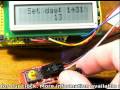
For now we will make our clock respond to the ‘menu’ button, and display the eight options when the knob is rotated. We will build on the sketch from example 7.4. Here is the result of doing this:
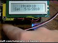
… and the resulting sketch: example 9.2.pdf.
Now it is time (ha!) to make those menu options actually do something. First we need our displaymenu() function to call the selected option. This can be done with a switch…case function. For example, I will put this code after the while loop:
  switch(readdial(8,1))

  {

    case 0: msethours; break;

    case 1: msetminutes; break;

    case 2: mset1224; break;

    case 3: msetday; break;

    case 4: msetmonth; break;

    case 5: msetyear; break;

    case 6: msetdow; break;

  }
There is no need for a seventh option (return to clock display) as this will default if the knob is in the ’7′ range. Notice I have already declared the name of the functions to call. All we have to do is create the individual functions. However there is one catch to work around, when it comes to setting time and date data, this is all done with the one function:
setDateDs1307(second, minute, hour, dayOfWeek, dayOfMonth, month, year);
So inside the function that (for example) sets the hour, immediately before setting the hour, read the rest of the values from the clock, and reset them back in with the setDateDS1307() function.
Once again the basic work has been done for you, please see this video:
… and the sketch: example 9.3.pdf. Although the contents of the LCD during the menus may be brief, the framework of the user interface has been created and can now be easily modified. For example, if you had a 20 x 4 character LCD, you could offer more help to the user.
But returning to the original task – emulating Grandfather’s alarm clock. We need an alarm!
Exercise 9.3
You guessed it – modify the clock in example 9.3 to have an alarm as well. User can set the alarm, and turn it on or off with the menu system. When the alarm sounds, the user should be able to turn off the alarm, Have fun!
How did you go? Here is a video demonstration of my work:
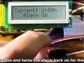
… and the sketch: exercise 9.3.pdf. That was really fun – I have a lot more clock ideas now.
I hope you enjoyed the change of pace this week and have a greater understanding on why we should create simpler human-machine interfaces wherever possible.
Well that is another week over. However, as usual I’m already excited about writing the next instalment… Congratulations to all those who took part and built something useful!
Please subscribe (see the top right of this page) to receive notifications of new articles.
High resolution photos are available from flickr.
If you have any questions at all please leave a comment (below). We also have a Google Group dedicated to the projects and related items on the website – please sign up, it’s free and we can all learn something. If you would like to showcase your work from this article, email a picture or a link to john at tronixstuff dot com. You might even win a prize!
Don’t forget to check out the range of gear at Little Bird Electronics!
So have fun, stay safe and see you soon for our next instalment!


