With Christmas just around the corner, you may start reminiscing about childhood races down the stairs to rip open presents under the tree. You’ll likely never do be any faster than you were when you were 12, but why not turn stair racing into an event anyway? Jared Dilley made that possible with his stairway stopwatch device.
It seems prudent to give you a disclaimer here: running up and down stairs is dangerous. We promise that your bones aren’t nearly as resilient as they were when you were a kid.
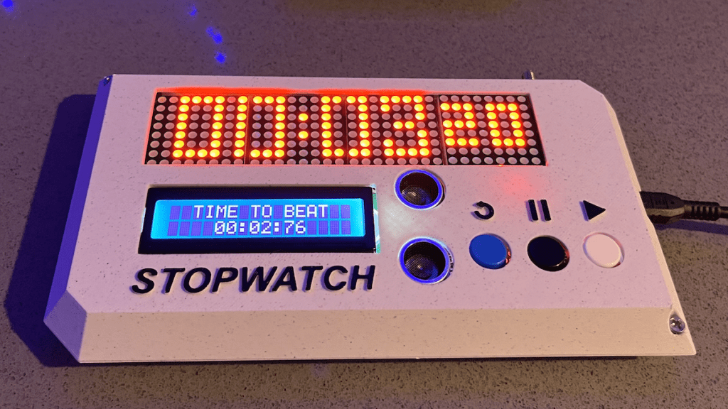
Dilley’s device is a timer system meant to measure the time it takes to ascend or descend a flight of stairs. It could also be used for races across flat ground or any other kind of terrain. That’s because it consists of two separate units that act as race gates. Each has an ultrasonic sensor to detect a passing person. Together, they measure the time it takes to pass the second gate after triggering the first.
Each unit contains an Arduino Nano board and the two boards communicate via HC-12 433MHz radio transceiver modules. Those have enough range to allow for positioning anywhere within a house, assuming you don’t live in a mansion with multiple wings. The primary unit displays the current record on a small LCD screen, as well as the most recent time on a large LED matrix panel. Both the primary and secondary units have nifty 3D-printed enclosures that Dilley designed to mount onto walls.
Before we had fancy digital clocks — or even spring-driven mechanical clocks — most methods for measuring short periods of time relied on gravity moving something in a consistent, repeatable way. Both water clocks and hour glasses work under that principle. But it isn’t very fun to watch grains of sand fall, which is why Brett Oliver built a kitchen timer that uses a rolling ball to count the seconds.
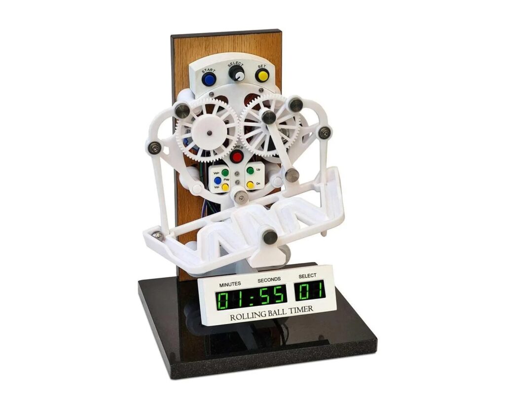
This project started with a rolling ball escapement designed by JBV Creative. That mechanism simply flips back and forth as a ball bearing rolls from one side of the track to the other. Perpetual motion is impossible, of course, so this mechanism relies on a weight to turn the gear system that pivots the track. The ball is just there for timing: when it reaches the end of the track, it pushes a lever that releases the mechanism and lets the weight drop a little. This will work until the weight reaches the ground or runs out of cord.
Oliver turned that mechanism into a kitchen timer by replacing the weight with a stepper motor controlled by an Arduino Nano board. Because the motor ultimately drives the mechanism, it can continue operating as long as it has power. An LCD display shows the remaining time and the user can set that with a few buttons. An MP3 module plays a user-configured sound effect when it reaches zero. The speed of the stepper motor determines the time it takes the ball to traverse the track and the default is five seconds, so the timer increments by five seconds with each pass.
This may not be more practical than a standard kitchen timer, but it is much more interesting to watch.
It’s a little known secret that when the Hackaday writers gather in their secret underground bunker to work on our plans for world domination, we often take breaks to play our version of the corporate “Buzzword Bingo”, where paradigms are leveraged and meetings circle back to loop in offline stakeholders, or something like that. Our version, however, is “Comment Line Bingo”, and right in the middle of the card is the seemingly most common comment of all: “You should have used a 555,” or variations thereof.
So it was with vicious glee that we came across the Trollduino V1.0 by the deliciously named [Mild Lee Interested]. It’s the hardware answer to the common complaint, which we’ll grant is often justified. The beautiful part of this is that Trollduino occupies the same footprint as an Arduino Uno and is even pin-compatible with the microcontroller board, or at least sort of. The familiar line of components and connectors sprout from the left edge of the board, and headers for shields line the top and bottom edges too. “Sketches” are implemented in hardware, with jumpers and resistors and capacitors of various values plugged in to achieve all the marvelous configurations the indispensable timer chip can be used for. And extra points for the deliberately provocative use of Comic Sans in the silkscreen.
Feature creep is typically something to be avoided, since watching a relatively simple project balloon into a rat’s nest of complexity often leads to ineffective, or even abandoned, projects. On the other hand, if you can maintain a tight focus, it’s not always a bad thing. [cbm80Amiga] shows us how to drill down and add specific features in this single-button timer without losing focus on what the original project was all about.
The timer is based on an Arduino Pro Mini and an HX1230 LCD with a simple piezo speaker for audible alerts. A single button controls operation of the timer, with short presses incrementing each digit and long presses moving on to the next digit. Controlling button presses this finely is a project in its own, but then [cbm80Amiga] moves on to other features such as backlight control, low power modes which allow it to operate for around two years on a single battery charge, preset times for various kitchen uses, and different appearance settings.
Honestly we aren’t sure how you could cram any more features on this timer without fundamentally altering the designed simplicity. It doesn’t fall into the abyss of feature creep while being packed with features, and it’s another example of how keeping things simple is often a recipe for success.
Reading the temperature of your environment is pretty easy right? A quick search suggests the utterly ubiquitous DHT11, which speaks a well documented protocol and has libraries for every conceivable microcontroller and platform. Plug that into your Arduino and boom, temperature (and humidity!) readings. But the simple solution doesn’t hit every need, sometimes things need to get more esoteric.
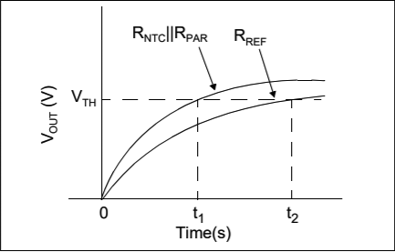
The technique summarized by an image from Microchip Appnote AN685
For years we’ve been watching [Edward]’s heroic efforts to build accessible underwater sensing hardware. When we last heard from him he was working on improving the accuracy of his Arduino’s measurements of the humble NTC thermistor. Now the goal is the same but he has an even more surprising plan, throw the ADC out entirely and sample an analog thermistor using digital IO. It’s actually a pretty simple trick based on an intuitive observation, that microcontrollers are better at measuring time than voltage.
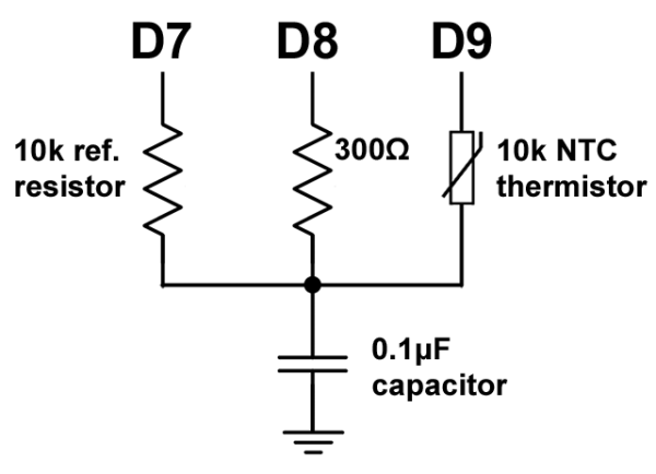
The basic circuit
The circuit has a minimum of four components: a reference resistor, the thermistor, and a small capacitor with discharge resistor. To sense you configure a timer to count, and an edge interrupt to capture the value in the timer when its input toggles. One sensing cycle consists of discharging the cap through the discharge resistor, enabling the timer and interrupt, then charging it through the value to measure. The value captured from the timer will be correlated to how long it took the cap to charge above the logic-high threshold when the interrupt triggers. By comparing the time to charge through the reference against the time to charge through the thermistor you can calculate their relative resistance. And by performing a few calibration cycles at different temperatures ([Edward] suggests at least 10 degrees apart) you can anchor the measurement system to real temperature.
The Arduino is built into a 3D printed enclosure, with several buttons for input. Rather unconventionally, a small e-paper display was chosen for the interface. This has the benefits of being easily readable outdoors during the day, as well as using very little power.
The device is simple to use, and makes training alone a breeze. The distance to be run can be selected, and the unit emits a series of beeps to indicate to the runner when to begin. The timer is placed at the finish line, and detects the runner passing by with an ultrasonic sensor.
It’s a useful build for sprint timing, and could be made even more versatile with a remote start function. If you need to time Hot Wheels instead of sprinters, don’t worry – there’s a build for you too. Video after the break.
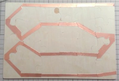
We can race against the clock when assembling jigsaw puzzles online but what about competing against each other in the real world? [HomeMadeGarbage] came up with the simplest of solutions with his jigsaw puzzle timer that stops only when the puzzle’s completely assembled.
Copper strip on back of puzzle
His simple solution was to attach copper foil tape to the back of the pieces, with overlap. He did this in a serpentine pattern to ensure that all pieces had a strip of the tape. The puzzle he used comes with a special container to assemble it in. At two corners of that container, he put two more pieces of copper foil, to which he soldered wires. Those two act as a switch. Only when the puzzle is completed will those two pieces be connected through the serpentine strip on the back of the puzzle.
Next, he needed a timer. The two wires from the puzzle container go to an Arduino UNO which uses an ILI9325 touch panel TFT display for both the start, stop, and reset buttons, and to show the time elapsed. Press the touch screen when it says START and begin assembling the puzzle. When the last piece is inserted, the serpentine strip of copper tape completes the circuit and only then does the Arduino program stop the timer. As you can see from the video below, the result makes doing the puzzle lots of fun.
Naturally, it takes some work to apply the copper tape and you wouldn’t likely do this for puzzles with a thousand pieces but most online puzzles don’t have many pieces either. It’s the fun of the race that matters, and with people taking turns, you want it to be quick anyway.
I am a crappy software coder when it comes down to it. I didn’t pay attention when everything went object oriented and my roots were always assembly language and Real Time Operating Systems (RTOS) anyways.
So it only natural that I would reach for a true In-Circuit-Emulator (ICE) to finish of my little OBDII bus to speed pulse generator widget. ICE is a hardware device used to debug embedded systems. It communicates with the microcontroller on your board, allowing you to view what is going on by pausing execution and inspecting or changing values in the hardware registers. If you want to be great at embedded development you need to be great at using in-circuit emulation.
Not only do I get to watch my mistakes in near real time, I get to make a video about it also.
Getting Data Out of a Vehicle
I’ve been working on a small board which will plug into my car and give direct access to speed reported on the Controller Area Network (CAN bus).
To back up a bit, my last video post was about my inane desire to make a small assembly that could plug into the OBDII port on my truck and create a series of pulses representing the speed of the vehicle for my GPS to function much more accurately. While there was a wire buried deep in the multiple bundles of wires connected to the vehicle’s Engine Control Module, I have decided for numerous reasons to create my own signal source.
At the heart of my project is the need to convert the OBDII port and the underlying CAN protocol to a simple variable representing the speed, and to then covert that value to a pulse stream where the frequency varied based on speed. The OBDII/CAN Protocol is handled by the STN1110 chip and converted to ASCII, and I am using an ATmega328 like found on a multitude of Arduino’ish boards for the ASCII to pulse conversion. I’m using hardware interrupts to control the signal output for rock-solid, jitter-free timing.
Walk through the process of using an In-Circuit Emulator in the video below, and join me after the break for a few more details on the process.
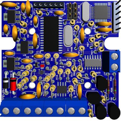
The Hardware
I revised the board since the last video and removed the support for the various protocols other than CAN, which is the non-obsolete protocol of the bunch. By removing a bunch of parts I was able to change the package style to through-hole which is easier for many home hobbyists, so you can leave the solder-paste in the ‘fridge.
The “Other Connector” on your Arduino
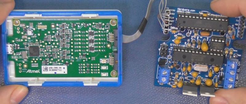
Unlike the Arduino which is ready to talk to your USB port when you take it out of the box, the ATmega chips arrive without any knowledge of how to go and download code, in other words it doesn’t have a boot loader. Consequently I have the In-Circuit-Serial-Programming (ICSP) pins routed to a pin header on my board so that I can program the part directly.
On this connector you’ll find the Reset line, which means with this header I can use a true ICE utilizing the debugWIRE protocol. Since the vast majority of designs that use an AVR chip do not repurpose the reset pin for GPIO, it is a perfect pin to use for ICE. All of the communications during the debug process will take place on the reset pin.
Enter the ICE
When designing a computer from scratch there is always the stage where nothing yet works. Simply put, a microprocessor circuit cannot work until almost every part of the design works; RAM, ROM, and the underlying buses all need to (mostly) work before simple things can be done. As a hardware engineer by trade I would always reach for an ICE to kick off the implementation; only after the Beta release would the ICE start to gather dust in the corner.
In the case of the ATmega, the debugging capabilities are built into the microcontroller itself. This is a much more straightforward implementation than the early days when we had to have a second isolated processor running off-board with its own local RAM/ROM.
One note mentioned in the video is that a standard Arduino’ish board needs to have the filter capacitors removed from the RESET line to allow the high speed data on the line for its debugWIRE usage.
The ICE I am using here is the one made by Atmel, and is compatible with Atmel Studio, there are also other models available such as the AVR Dragon.
ICEyness
The ICE allows us to download and single step our code while being able to observe and overwrite RAM and I/O Registers from the keyboard. We are able to watch the program step by step or look underneath at the actual assembly code generated by the compiler. We can watch variables and locations directly in RAM or watch the C language counterparts. It’s also possible to jump over a sub-routine call in the instance of just wanting to see the result without all of the processing.
This video was really about finishing the OBDII circuit so I didn’t really have the time to go over everything an ICE can do, maybe I will do a post dedicated to just the ICE and development environment next time.
[Apachexmd] wanted to do something fun for his three-year-old son’s birthday party. Knowing how cool race cars are, he opted to build his own Hot Wheels drag race timer. He didn’t take the easy way out either. He put both his electronics and 3D printing skills to the test with this project.
The system has two main components. First, there’s the starting gate. The cars all have to leave the gate at the same time for a fair race, so [Apachexmd] needed a way to make this electronically controlled. His solution was to use a servo connected to a hinge. The hinge has four machine screws, one for each car. When the servo is rotated in one direction, the hinge pushes the screws out through holes in the track. This keeps the cars from moving on the downward slope. When the start button is pressed, the screws are pulled back and the cars are free to let gravity take over.
The second component is the finish line. Underneath the track are four laser diodes. These shine upwards through holes drilled into the track. Four phototransistors are mounted up above. These act as sensors to detect when the laser beam is broken by a car. It works similarly to a laser trip wire alarm system. The sensors are aimed downwards and covered in black tape to block out extra light noise.
Also above the track are eight 7-segment displays; two for each car. The system is able to keep track of the order in which the cars cross the finish line. When the race ends, it displays which place each car came in above the corresponding track. The system also keeps track of the winning car’s time in seconds and displays this on the display as well.
The system runs on an Arduino and is built almost exclusively out of custom designed 3D printed components. Since all of the components are designed to fit perfectly, the end result is a very slick race timer. Maybe next [Apachexmd] can add in a radar gun to clock top speed. Check out the video below to see it in action.
Most of us have probably seen clocks or numerical displays that flip sequential boards to display the next number in a sequence. If you wanted to take that a step further, you could make a replica of “Dottie,” which flips small dots as pixels. As the great video below says, it makes a “pleasant mechanical flipping sound all day.” It also tells the date, chimes every 15 minutes, and gives an animation show once an hour.
Planet Arduino is, or at the moment is wishing to become, an aggregation of public weblogs from around the world written by people who develop, play, think on Arduino platform and his son. The opinions expressed in those weblogs and hence this aggregation are those of the original authors. Entries on this page are owned by their authors. We do not edit, endorse or vouch for the contents of individual posts. For more information about Arduino please visit www.arduino.cc
You are currently browsing the archives for the timer category.