As the world becomes more and more digital, there are still a few holdouts from the analog world we’ve left behind. Vinyl records are making quite the comeback, and film photography is still hanging on as well. While records and a turntable have a low barrier for entry, photography is a little more involved, especially when developing the film. But with the right kind of equipment you can bridge the gap from digital to analog with a darkroom setup that takes digital photographs and converts them to analog prints.
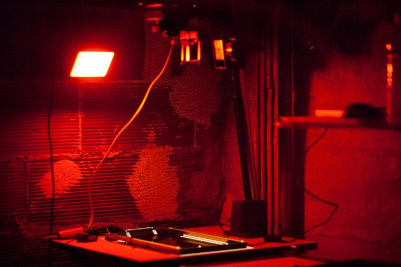
The project’s creator, [Muth], has been working on this project since he found a 4K monochrome display. These displays are often used in resin 3D printers, but he thought he could put them to use developing photographs. This is much different from traditional darkroom methods, though. The monochrome display is put into contact with photo-sensitive paper, and then exposed to light. Black pixels will block the light while white pixels allow it through, creating a digital-to-analog negative of sorts. With some calibration done to know exactly how long to expose each “pixel” of the paper, the device can create black-and-white analog images from a digital photograph.
[Muth] notes that this method isn’t quite as good as professional print, but we wouldn’t expect it to be. It creates excellent black-and-white prints with a unique method that we think generates striking results. The 4K displays needed to reproduce this method aren’t too hard to find, either, so it’s fairly accessible to those willing to build a small darkroom to experiment. For those willing to go further, take a look at some other darkroom builds we’ve seen in the past.
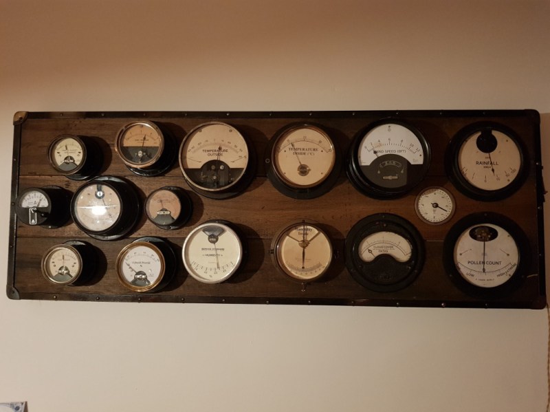
For most of us, getting weather information is as trivial as unlocking a smartphone or turning on a computer and pointing an app or browser at one’s weather site of choice. This is all well and good, but it lacks a certain panache that old weather stations had with their analog dials and stained wood cases. The weather station that [BuildComics] created marries both this antique aesthetic with modern weather data availability, and then dials it up a notch for this enormous analog weather station build.
The weather station uses 16 discrete dials, each modified with a different label for the specific type of data displayed. Some of them needed new glass, and others also needed coils to be modified to be driven with a lower current than they were designed as well, since each would be driven by one of two Arduinos in this project. Each are tied to a microcontroller output via a potentiometer which controls the needle’s position for the wildly different designs of meter. The microcontrollers themselves get weather information via the internet, which allows for about as up-to-date information about the weather as one could gather first-hand.
The amount of customization of these old meters is impressive, and what’s even more impressive is the project’s final weight. [BuildComics] reports that it took two people just to lift it onto the wall mount, which is not surprising given the amount of iron in some of these old analog meters. And, although not as common in the real world anymore, these old antique meters have plenty of repurposed uses beyond weather stations as well.
Reading the temperature of your environment is pretty easy right? A quick search suggests the utterly ubiquitous DHT11, which speaks a well documented protocol and has libraries for every conceivable microcontroller and platform. Plug that into your Arduino and boom, temperature (and humidity!) readings. But the simple solution doesn’t hit every need, sometimes things need to get more esoteric.
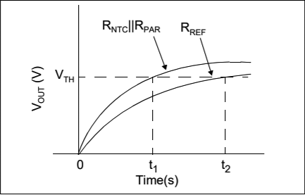
The technique summarized by an image from Microchip Appnote AN685
For years we’ve been watching [Edward]’s heroic efforts to build accessible underwater sensing hardware. When we last heard from him he was working on improving the accuracy of his Arduino’s measurements of the humble NTC thermistor. Now the goal is the same but he has an even more surprising plan, throw the ADC out entirely and sample an analog thermistor using digital IO. It’s actually a pretty simple trick based on an intuitive observation, that microcontrollers are better at measuring time than voltage.
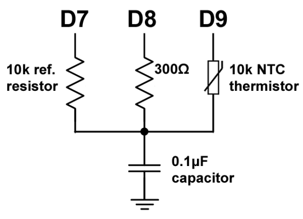
The basic circuit
The circuit has a minimum of four components: a reference resistor, the thermistor, and a small capacitor with discharge resistor. To sense you configure a timer to count, and an edge interrupt to capture the value in the timer when its input toggles. One sensing cycle consists of discharging the cap through the discharge resistor, enabling the timer and interrupt, then charging it through the value to measure. The value captured from the timer will be correlated to how long it took the cap to charge above the logic-high threshold when the interrupt triggers. By comparing the time to charge through the reference against the time to charge through the thermistor you can calculate their relative resistance. And by performing a few calibration cycles at different temperatures ([Edward] suggests at least 10 degrees apart) you can anchor the measurement system to real temperature.
Meter clock: keeping “current” time. Read more about the clock:
I’ve seen a few meter clocks in my travels of the web, and I love the idea. A few days ago, I decided that I must have one of my own. Such began the “How to do it” pondering cycle. I had seen builds where the face plate of the meter is replaced. This works, but I wanted to try and find a way to do it without modifying the meter, if possible. After some more ponderation, I came up with what I think is a serviceable idea.
I came across this style of milliamp meter on Amazon. They’re not quite 0-60 mA, but the 0-100 mA (a 0-20mA meter for the hours) is close enough. And they were cheap. So yay.
Part of my requirements were that the clock run off of an Arduino Pro Mini I had lying around, and with minimal additional parts. In order to drive the meters with some degree of precision, I would use the PWM pins to vary the effective voltage across a resistor in series with the meter. This would, by the grace of Ohm’s Law, induce a current that, based on the PWM duty cycle, would be scaled in such a way as to move the needle on the meter to the corresponding hour, minute, or second.
One minor issue came up in the form of the max current the GPIO pins on the ATMega328 chip can source/sink. The pins can source/sink a maximum of 40mA, a bit far from the 60mA needed for the minutes and seconds meters. Enter the transistor.
Using a simple NPN transistor switch circuit, I was able to provide the current for the minute and second meters from the 5V supply. The PWM signals switch the respective transistors on and off, effectively varying the voltage across the resistors in series with the meters.
The resistor between 5V and the meter is actually 2 1/4 watt 100 Ohm resistors in parallel for an effective resistance of 50 Ohms. The two in parallel was necessary as 5V x 0.06A = 0.3W (more than 0.25 that a single 1/4W resistor can handle safely).
We spent a little bit of time at the TI booth at Maker Faire to film a pair of interviews. The first is with [Bill Esposito] who is grinding away on his PhD. at Stanford. He’s showing off an Analog Shield for Arduino. He describes it as “an attempt to bring the analog bench to an Arduino shield”. We think this is a fantastic idea as most who are learning digital electronics through Arduino have little or no experience with analog circuitry. This is a nice gateway drug for the concepts.
The analog shield has a supply good for +/- 7.5 volts, 4-channel ADC, 4-channel DAC, and gets 100k samples at 16-bits. He showed us a spectrum analyzer using Fast Fourier Transform on the incoming signal from a microphone. He also built a function generator around the shield. And finally a synthesizer which plays MIDI files.
In the second half of the video we take a look at [Trey German's] work on a PCB-based quadcopter. His goal is to reduce the power consumption which will equate to longer flying times. To this end he chose the DRV8312 and a Piccolo to control each sensorless, brushless DC motor. The result should be 10% lower power consumption that his previous version.
Data Dial Dashboard joins our beginner-friendly electronics series, Weekend Projects, as a moderately difficult build. The case design and layout is fun and simple, made from balsa wood and uses ink or laserjet printouts for all the displays (or a laser cutter for those with access to one). Even the required soldering is nominal and pretty straightforward. The challenge then arises from what information to display, and how.
The Data Dial Dashboard brings back the fun of old-school analog dial gauges while updating them with internet connectivity. In this project we will use an Arduino, Ethernet shield, and 3 servos to create a system for tracking global earthquake activity. The data is pulled from the USGS Real-time Data Feeds page. With a little hacking, it is easily adapted to track your unanswered e-mail count, the speed of your internet connection, the price of rice in Rhode Island, or any other data you can scrape off the 'net!
In this chapter we’ll look at how you can measure smaller voltages with greater accuracy using the analogue input pins on your Arduino or compatible board in conjunction with the AREF pin. However first we’ll do some revision to get you up to speed. Please read this post entirely before working with AREF the first time.
Revision
You may recall from the first few chapters in our tutorial series that we used the analogRead() function to measure the voltage of an electrical current from sensors and so on using one of the analogue input pins. The value returned from analogRead() would be between zero an 1023, with zero representing zero volts and 1023 representing the operating voltage of the Arduino board in use.
And when we say the operating voltage – this is the voltage available to the Arduino afterthe power supply circuitry. For example, if you have a typical Arduino Uno board and run it from the USB socket – sure, there is 5V available to the board from the USB socket on your computer or hub – but the voltage is reduced slightly as the current winds around the circuit to the microcontroller – or the USB source just isn’t up to scratch.
This can easily be demonstrated by connecting an Arduino Uno to USB and putting a multimeter set to measure voltage across the 5V and GND pins. Some boards will return as low as 4.8 V, some higher but still below 5V. So if you’re gunning for accuracy, power your board from an external power supply via the DC socket or Vin pin – such as 9V DC. Then after that goes through the power regulator circuit you’ll have a nice 5V, for example:
This is important as the accuracy of any analogRead() values will be affected by not having a true 5 V. If you don’t have any option, you can use some maths in your sketch to compensate for the drop in voltage. For example, if your voltage is 4.8V – the analogRead() range of 0~1023 will relate to 0~4.8V and not 0~5V. This may sound trivial, however if you’re using a sensor that returns a value as a voltage (e.g. the TMP36 temperature sensor) – the calculated value will be wrong. So in the interests of accuracy, use an external power supply.
Why does analogRead() return a value between 0 and 1023?
This is due to the resolution of the ADC. The resolution (for this article) is the degree to which something can be represented numerically. The higher the resolution, the greater accuracy with which something can be represented. We measure resolution in the terms of the number of bits of resolution.
For example, a 1-bit resolution would only allow two (two to the power of one) values – zero and one. A 2-bit resolution would allow four (two to the power of two) values – zero, one, two and three. If we tried to measure a five volt range with a two-bit resolution, and the measured voltage was four volts, our ADC would return a numerical value of 3 – as four volts falls between 3.75 and 5V. It is easier to imagine this with the following image:
So with our example ADC with 2-bit resolution, it can only represent the voltage with four possible resulting values. If the input voltage falls between 0 and 1.25, the ADC returns numerical 0; if the voltage falls between 1.25 and 2.5, the ADC returns a numerical value of 1. And so on. With our Arduino’s ADC range of 0~1023 – we have 1024 possible values – or 2 to the power of 10. So our Arduinos have an ADC with a 10-bit resolution.
So what is AREF?
To cut a long story short, when your Arduino takes an analogue reading, it compares the voltage measured at the analogue pin being used against what is known as the reference voltage. In normal analogRead use, the reference voltage is the operating voltage of the board. For the more popular Arduino boards such as the Uno, Mega, Duemilanove and Leonardo/Yún boards, the operating voltage of 5V. If you have an Arduino Due board, the operating voltage is 3.3V. If you have something else – check the Arduino product page or ask your board supplier.
So if you have a reference voltage of 5V, each unit returned by analogRead() is valued at 0.00488 V. (This is calculated by dividing 1024 into 5V). What if we want to measure voltages between 0 and 2, or 0 and 4.6? How would the ADC know what is 100% of our voltage range?
And therein lies the reason for the AREF pin. AREF means Analogue REFerence. It allows us to feed the Arduino a reference voltage from an external power supply. For example, if we want to measure voltages with a maximum range of 3.3V, we would feed a nice smooth 3.3V into the AREF pin – perhaps from a voltage regulator IC. Then the each step of the ADC would represent around 3.22 millivolts (divide 1024 into 3.3).
Note that the lowest reference voltage you can have is 1.1V. There are two forms of AREF – internal and external, so let’s check them out.
External AREF
An external AREF is where you supply an external reference voltage to the Arduino board. This can come from a regulated power supply, or if you need 3.3V you can get it from the Arduino’s 3.3V pin. If you are using an external power supply, be sure to connect the GND to the Arduino’s GND pin. Or if you’re using the Arduno’s 3.3V source – just run a jumper from the 3.3V pin to the AREF pin.
To activate the external AREF, use the following in void setup():
analogReference(EXTERNAL); // use AREF for reference voltage
This sets the reference voltage to whatever you have connected to the AREF pin – which of course will have a voltage between 1.1V and the board’s operation voltage.
Very important note – when using an external voltage reference, you must set the analogue reference to EXTERNAL before using analogRead(). This will prevent you from shorting the active internal reference voltage and the AREF pin, which can damage the microcontroller on the board.
If necessary for your application, you can revert back to the board’s operating voltage for AREF (that is – back to normal) with the following:
analogReference(DEFAULT);
Now to demonstrate external AREF at work. Using a 3.3V AREF, the following sketch measures the voltage from A0 and displays the percentage of total AREF and the calculated voltage:
#include <LiquidCrystal.h>
LiquidCrystal lcd(8,9,4,5,6,7);

int analoginput = 0; // our analog pin
int analogamount = 0; // stores incoming value
float percentage = 0; // used to store our percentage value
float voltage =0; // used to store voltage value

void setup()
{
  lcd.begin(16, 2);
  analogReference(EXTERNAL); // use AREF for reference voltage
}

void loop()
{
  lcd.clear();
  analogamount=analogRead(analoginput);
  percentage=(analogamount/1024.00)*100;
  voltage=analogamount*3.222; // in millivolts
  lcd.setCursor(0,0);
  lcd.print("% of AREF: ");
  lcd.print(percentage,2);
  lcd.setCursor(0,1);
  lcd.print("A0 (mV): ");
  lcd.println(voltage,2);
  delay(250);
}
The results of the sketch above are shown in the following video:
Internal AREF
The microcontrollers on our Arduino boards can also generate an internal reference voltage of 1.1V and we can use this for AREF work. Simply use the line:
analogReference(INTERNAL);
For Arduino Mega boards, use:
analogReference(INTERNAL1V1);
in void setup() and you’re off. If you have an Arduino Mega there is also a 2.56V reference voltage available which is activated with:
analogReference(INTERNAL2V56);
Finally – before settling on the results from your AREF pin, always calibrate the readings against a known good multimeter.
Conclusion
The AREF function gives you more flexibility with measuring analogue signals. If you are interested in using specific ADC components, we have tutorials on the ADS1110 16-bit ADC and the NXP PCF 8591 8-bit A/D and D/A IC.
Stay tuned for upcoming Arduino tutorials by subscribing to the blog, RSS feed (top-right), twitter or joining our Google Group. And if you enjoyed the tutorial, or want to introduce someone else to the interesting world of Arduino – check out my book (now in a third printing!) “Arduino Workshop” from No Starch Press.
One pixel might make you bored but it gives you something interesting when pixels make a form together. This WPD64 has been presented at a generative art show in NYC recently.
I used Arduino Uno and four of Adafruit 16-Channel 12-bit PWM/Servo Shield to control 64 servos. Laser cutting service from Pololu.com for the front cover which should have 64 square holes at the perfect grid.
Planet Arduino is, or at the moment is wishing to become, an aggregation of public weblogs from around the world written by people who develop, play, think on Arduino platform and his son. The opinions expressed in those weblogs and hence this aggregation are those of the original authors. Entries on this page are owned by their authors. We do not edit, endorse or vouch for the contents of individual posts. For more information about Arduino please visit www.arduino.cc
You are currently browsing the archives for the analog category.