This is part of a series titled “Getting Started with Arduino!” by John Boxall – A tutorial on the Arduino universe. The first chapter is here, the complete series is detailed here.
Welcome back fellow arduidans!
This chapter we will spend some more time with the rotary encoder by using it to control a clock, look at ways of driving a common-anode LED display with Arduino, and make a usable alarm clock with which we can start to move from the prototype stage to an actual finished product – something you would be proud to give to someone.
So off we go…
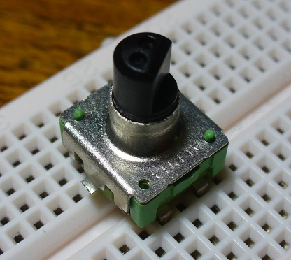
In chapter eleven, we looked at getting some values from the rotary encoder. Not the easiest way of receiving user input, but certainly interesting. This week I have an example for you where the encoder is used for setting the time of a digital clock.
Example 12.1
This example is basically two previous projects mashed together. It consists of the LED digital clock from exercise 7.1, and the rotary encoder sketch from example 11.2. The sketch was quite simple in theory, but somewhat complex in execution. The idea was to read the decoder, and after every read, display the time. However, if the encoder’s button was pressed, the time set function would be activated. At this point, you turn the encoder in one direction to set the hours, and the other direction to set the minutes. Then press the button again to set that time and return to normal operations.
To recreate it you will need:
- Your standard Arduino setup (computer, cable, Duemilanove or 100% compatible)
- Seven 560 ohm 1/4 watt resistors
- Four 1 kilo ohm 1/4 resistors
- Four BC548 NPN transistors (if you cannot find these, you can use 2N3904)
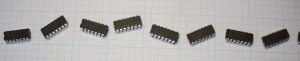
- Two 74HC595 shift registers
- DS1307 timer IC circuit components (see this schematic from chapter seven) or a pre-built module
- Solderless breadboard and connecting wires
Here is the sketch for your perusal: example 12.1.pdf, and the matching schematic (sorry, I forgot to add the DS1307 module – see example 12.2 schematic below for how to do this):

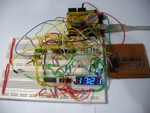
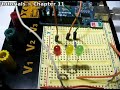
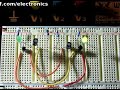
… in real life:

and a video clip:
After watching that clip you can soon see that there is an issue with the encoder. As a normal switch can bounce (turn on and off very very quickly in the latter part of operation), so can a rotary encoder. That is why it would sometimes return a result of clockwise, instead of anti-clockwise. Furthermore, they are right little pains when trying to use in a breadboard, so if you were going to use one in greater lengths, it would pay to make up your own little breakout board for it. Therefore at this stage we will leave the encoder for a while.
You may also have noticed the extra shield between the real time clock shield (yellow) and the TwentyTen arduino board. It is the Screwshield for Arduino – reviewed here. It is very useful to making a stronger connection to the I/O pins, or using normal multi-core wires.
Next on the agenda is the common-anode LED display. Normally the LED display we have demonstrated in the past has been common-cathode, and very easy to use. Current would flow from the power supply, through the shift register’s outputs (for example the 74HC595), through current-limiting resistors, into the LED segment, then off to earth via the cathode. Current flows through a diode from the anode to the cathode, and finally back to earth/ground. For a refresher on diodes, please read this article.
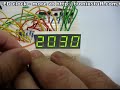
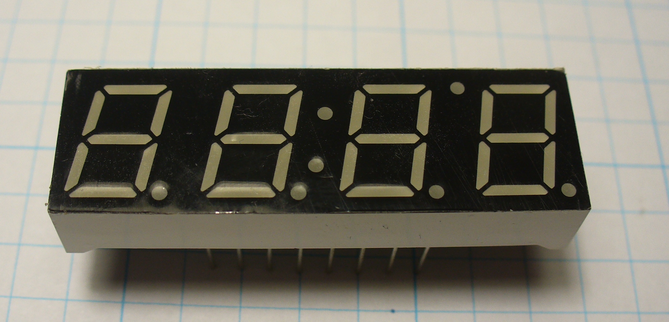
The other month I found this useful LED display:

Absolutely perfect for our clock experimentations. A nice colon in the middle, and another LED between the third and fourth digit which could make a good indicator of some sort. However the one catch (always a catch…) is that is was common-anode. This means that current starts from the power supply, through the common anode pin for the particular digit, then the LED segment, the LED’s individual cathode pin, through the current-limiting resistor and then to ground. With the current flowing in the opposite direction via a common anode, we can’t just hook the display up to our 74HC595 shift register.
Therefore, we will need the shift register to control switches to allow the current to flow through each segment, just like we have done previously controlling the cathodes of a common cathode display (see example 12.1). So to control the digits of this new display, we will need twelve switches (eight for the segments of the digit, and four to control the anodes). That would mean twelve BC548 transistors and 10k ohm resistors, and a lot of mess.
Example 12.2
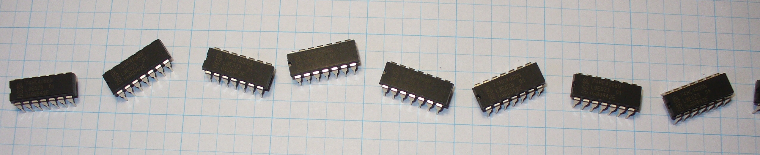
Instead we will now use the 74HC4066 quad bilateral switch IC. I have reviewed this chip being used with Arduinos in a separate article here. The 74HC4066 is quite a common chip, available from many suppliers including: Farnell/Newark (part number 380957), Digikey (part number 568-1463-5-ND) or Mouser (771-74HC4066N). If you cannot find them, email me and I can sell you some at cost plus postage. Once you have a understanding of this IC, please consider the following circuit:

Most of this should be easily understood. One shift register is controlling the anodes, turning them on and off via a 74HC4066. In past examples this shift register would have turned off common cathodes via a 10k resistor and an NPN transistor. The other shift register is controlling the individual LEDs for each digit via a pair of 74HC4066s (as they only have four switches per IC).
Here is the sketch, this should be quite a familiar piece of code for you by now: example 12.2.pdf.
To recreate it you will need:
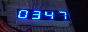
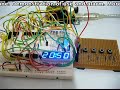
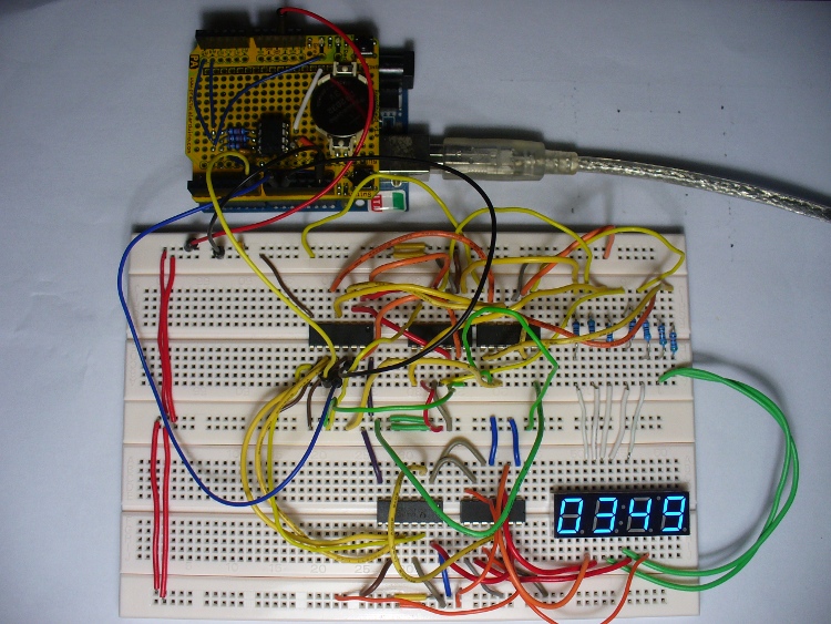
And here is the result, with red and a blue display.

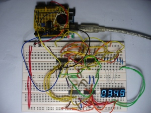
And the usual board layout:
Question – Do you think the time shown on the display was correct when I took the photo?  Personally the blue looks really good in a dark background. You can also get them in yellow and green.

Moving along. Now and again, you often want to have a few buttons in use for user input, however the cheap ones don’t really like to sit in a breadboard. Naturally, you could make your own “button shield”, which would be very admirable, but then it would be preset to certain pins, which could interfere with your project. I had the same problem in writing this chapter, so came up with this example of an external “button panel” to make life easier.
Example 12.3
Here is the schematic, nothing complex at all – just four buttons and the required 10k ohm pull-down resistors:

and the finished product:

This was a quick job, as I will need to use a few buttons in the near future. Have also put some rubber feet on the bottom to stop the solder joints scratching the surface of the bench. Originally I was going to chop off the excess board at the top, but instead will add some LEDs to it after finishing this article. However using this button board will save a lot of frustration by not trying to jam the buttons into a breadboard.

Exercise 12.1
Now it is time for you to do some work. From this chapter onwards, we will be working on making a small alarm clock – something you could use. Just like the six million dollar man, we have the capability, the technology, and so on … except for Steve Austin. So this chapter, your task is to create and breadboard the circuit and the underlying sketch. Using the LED display from example 12.1, your clock will have a menu option to set the time, alarm time, turn on and off the alarm, a snooze button – and also switch the display on and off (so you don’t stare at it when you should be trying to sleep).
You could either use a DS1307 module, or the raw parts. For an explanation of the circuitry, please see this post about making a RTC shield. You can always change it when we get to making a real prototype. The same with the Arduino – but for this exercise just stick with the normal board. Later on we will use a bare circuit the same as in chapter ten. With regards to user input, it’s up to you. A rotary encoder could be a real PITA, my example below just uses buttons. Anyhow, off you go!
Parts you will need:
- Your standard Arduino setup (computer, cable, Duemilanove or 100% compatible)
- Seven 560 ohm 1/4 watt resistors
- DS1307 timer IC circuit components (see this schematic from chapter seven) or a pre-built module
- Two 74HC595 shift registers
- Three 74HC4066 quad bilateral switch ICs
- Four normally open buttons or a board as described in example 12.3
- Solderless breadboard and connecting wires
- LED clock display module
Here is my interpretation of the answer to the exercise, the sketch: exercise 12.1.pdf. Although this is a particularly long sketch for our examples, it is broken up into many functions which are quite modular, so you can easily follow the flow of the sketch if you start at void loop(). All of the types of functions used have been covered in the past tutorials. In then next chapters we will add more functions, such an an adjustable snooze, selectable blinking colon, and so on. If you have any questions, please ask.
The buttons have several functions. In normal clock display mode, button one is for menu, two turns the alarm on, three turns it off, and four turns the display on and off. If you press menu, button two is to select time set, three for alarm set, and four is like an enter button. When in the time/alarm set modes, button one increases the hour, button two increases minutes in units of ten, and button three increases minutes in ones, and four is enter. When the alarm activates, button four turns it off.
The schematic is just example 12.2 and example 12.3 connected together, however the first button on the external board is connected to digital pin 8 instead of 1.
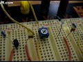
So here is a photo of our work in progress:
And a video clip showing the various functions of the clock in operation:
Well that is another chapter over. However, as usual I’m already excited about writing the next instalment… Congratulations to all those who took part and built something useful!
Please subscribe (see the top right of this page) to receive notifications of new articles. High resolution photos are available from flickr.
If you have any questions at all please leave a comment (below). We also have a Google Group dedicated to the projects and related items on the website – please sign up, it’s free and we can all learn something. If you would like to showcase your work from this article, email a picture or a link to john at tronixstuff dot com. You might even win a prize!
Don’t forget to check out the range of gear at Little Bird Electronics!
So have fun, stay safe and see you soon for our next instalment, hopefully by 23rd July 2010.


