Posts | Comments

Planet Arduino

Archive for the ‘resistor-capacitor’ Category

Hello everyone

Today we are going to continue exploring alternating current, with regards to how resistors and capacitors deal with AC. This chapter is part two, chapter one is here.

To help with the explanations, remember this diagram:

That is, note that there are three possible voltage values, Vpp, Vp and Vrms. Moving on. Alternating current flows through various components just like direct current. Let’s examine some components and see.

First, the resistor. It operates in the same way with AC as it does DC, and the usual calculations apply with regards to Ohm’s law, dividing voltage and so on. However you must keep in mind the type of voltage value. For example, 10Vrms + 20Vpp does NOT equal 30 of anything. But we can work it out. 20Vpp is 10Vp,  which is 7.07Vrms… plus 10Vrms = 17.07Vrms. Therefore, 10Vrms + 20Vpp = 17.07Vrms.

Furthermore, when using Ohm’s law, or calculating power, the result of your equation must always reflect the type of voltage used in the calculations. For example:


Next, the capacitor. Capacitors oppose the flow of alternating current in an interesting way – in simple terms, the greater the frequency of the current, the less opposition to the current. However, we call this opposition reactance, which is measured in ohms. Here is the formula to calculate reactance:


the result Xc is measured in Ohms, f is frequency is Hertz, and C is capacitance in Farads. Here are two examples – note to convert the value of the capacitor back to Farads


Also consider if you have identical frequencies, a smaller capacitor will offer a higher resistance than a larger capacitor. Why is this so? A smaller capacitor will reach the peak voltages quicker as it charges in less time (as it has less capacitance); wheras a larger capacitor will take longer to charge and reach the peak voltage, therefore slowing down the current flow which in turn offers a higher reactance.

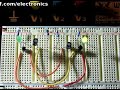
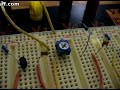
Resistors and capacitors can also work together as an AC voltage divider. Consider the following schematic:

As opposed to a DC voltage divider, R2 has been replaced with C1, the 0.1 uF capacitor. In order to calculate Vout, we will need the reactance of C1 – and subsitute that value for R2:

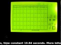
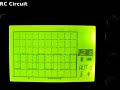
However, once the voltage has been divided, Vout has been transformed slightly – it is now out of phase. This means that Vout oscillates at the same frequency, but at different time intervals than Vin. The easiest way to visualise this is with an oscilloscope, which you can view below:

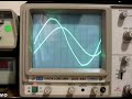
Please note that my CRO is not in the best condition. In the clip it was set to a time base of 2 milliseconds/division horizontal and 5 volts/division vertical.

Thus ends chapter two of our introduction to alternating current. I hope you understood and can apply what we have discussed today. As always, thank you for reading and I look forward to your comments and so on. Furthermore, don’t be shy in pointing out errors or places that could use improvement, you can either leave a comment below or email me – john at tronixstuff dot com.

Please subscribe using one of the methods at the top-right of this web page to receive updates on new posts. Or join our Google Group and post your questions there.

Otherwise, have fun, be good to each other – and make something! :)

Hello readers

Today we continue down the path of analog electronics theory by stopping by for an introductory look at the RC circuit. That’s R for resistor, and C for capacitor. As we know from previous articles, resistors can resist or limit the flow of current in a circuit, and a capacitor stores electric current for use in the future. And – when used together – these two simple components can be used for many interesting applications such as timing and creating oscillators of various frequencies.

How is this so? Please consider the following simple circuit:

When the switch is in position A, current flows through R1 and into the capacitor C1 until it is fully charged. During this charging process, the voltage across the capacitor will change, starting from zero until fully charged, at which point the voltage will be the same as if the capacitor had been replaced by a break in the circuit – in this case 6V. Fair enough. But how long will the capacitor take to reach this state? Well the time taken is a function of several things – including the value of the resistor (R1) as it limits the flow of current; and the size of the capacitor – which determines how much charge can be stored.

If we know these two values, we can calculate the time constant of the circuit. The time constant is denoted by the character zeta (lower-case Greek Z).

The time constant is the time taken (in seconds) by the capacitor C that is fed from a resistor R to charge to a certain level. The capacitor will charge to 63% of the final voltage in one time constant, 85% in two time constants, and 100% in five time constants. If you graphed the % charge against time constant, the result is exponential. That is:

Now enough theory – let’s put this RC circuit to practice to see the voltage change across the capacitor as it charges. The resistor R1 will be 20k ohm, the capacitor 1000 uF.

Our time constant will be R x C which will be 20000 ohms x 0.001 farads, which equals 20 (seconds).  Notice the unit conversion – you need to go back to ohms and farads not micro-, pico- or nanofarads. So our example will take 20 seconds to reach 63% of final voltage, and 100 seconds to reach almost full voltage. This is assuming the values of the resistor and capacitor are accurate. The capacitor will have to be taken on face value as I can’t measure it with my equipment, and don’t have the data sheet to know the tolerance. The resistor measured at 19.84 k ohms, and the battery measured 6.27 volts. Therefore our real time constant should be around 19.84 seconds, give or take.

First of all, here is a shot of the little oscilloscope measuring the change in voltage over the capacitor with respect to time. The vertical scale is 1v/division:

And here is the multimeter measuring the voltage next to a stopwatch. (crude yet effective, no?)

The two videos were not the most accurate, as it was difficult to synchronise the stopwatch and start the circuit, but I hope you could see the exponential relationship between time and voltage.

What about discharging? Using the circuit above, if we moved the switch to B after charging the capacitor –  and R2 was also 20k ohm – how long would it take to discharge the capacitor? Exactly the same as charging it! So one time constant to discharge 63% and so on. So you can take the graph from above and invert it as such:

How can we make use of an RC circuit?

I’m glad you asked. Consider the following circuit:

When power is applied, the capacitor starts to charge, and in doing so allows current to flow to the emitter of the transistor, which turns on the LED. However as the capacitor charges, less current passes to the base of the transistor, eventually turning it off. Therefore you can calculate time constants and experiment to create an off timer. However, a preferable way would be to make use of a 555 timer. For example, an RC combination is used to set the pulse length used in astable timing applications, for example using R1, R2 and C1:

(For more information on the 555 timer, please read this article)

Another use of the RC circuit is oscillating. Due to varying capacitor values due to tolerance, you most likely cannot make precision frequency generators, but you can still have some fun and make useful things. Here is a classic oscillator example – an astable multivibrator:

What is going on here? Here it is in action:

and here is one side being measured on the little scope:

We have two RC circuits, each controlling a transistor. When power is applied, there is no way to determine which side will start first, as this depends on the latent charge in the capacitors and the exact values of the resistors and capacitors. So to start let’s assume the left transistor (Q1) and LED are on; and the right transistor (Q2) and LED are off. The voltage at collector of Q1 will be close to zero as it is on. And the voltage at the base of Q2 will also be close to zero as C2 will initially be discharged. But C2 will now start charging via R4 and base of Q1 to around 5.4V (remember the 0.6v loss over the base-emitter junction of a transistor). While this is happening, C1 starts charging through R2. Once the voltage difference reaches 0.6V over the capacitor, Q2 is turned on.

But when Q2 is on, the voltage at the collector drops to zero, and C2 is charged, so it pulls the voltage at the base of Q1 to -5.4v, turning it off and the left LED. C1 starts charging via R1, and C2 starts charging via R3 until it reaches 0.6v. Then Q1 turns on, bringing the base of Q2 down to -5.4V – switching it off. And the whole process repeats itself. Argh. Now you can see why Arduino is so popular.

Time for a laugh – here is the result of too much current through a trimpot:

So there you have it – the RC circuit. Part of the magic of analogue electronics!

As always, thank you for reading and I look forward to your comments and so on. Furthermore, don’t be shy in pointing out errors or places that could use improvement. Please subscribe using one of the methods at the top-right of this web page to receive updates on new posts. Or join our new Google Group.

Otherwise, have fun, be good to each other – and make something! :)


  • Newsletter

    Sign up for the PlanetArduino Newsletter, which delivers the most popular articles via e-mail to your inbox every week. Just fill in the information below and submit.

  • Like Us on Facebook