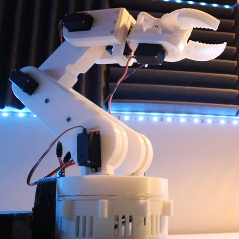
Ever wanted your own gesture-controlled robot arm? [EbenKouao]’s DIY Arduino Robot Arm project covers all the bases involved, but even if a robot arm isn’t your jam, his project has plenty to learn from. Every part is carefully explained, complete with source code and a list of required hardware. This approach to documenting a project is great because it not only makes it easy to replicate the results, but it makes it simple to remix, modify, and reuse separate pieces as a reference for other work.
[EbenKouao] uses a 3D-printable robotic gripper, base, and arm design as the foundation of his build. Hobby servos and a single NEMA 17 stepper take care of the moving, and the wiring and motor driving is all carefully explained. Gesture control is done by wearing an articulated glove upon which is mounted flex sensors and MPU6050 accelerometers. These sensors detect the wearer’s movements and turn them into motion commands, which in turn get sent wirelessly from the glove to the robotic arm with HC-05 Bluetooth modules. We really dig [EbenKouao]’s idea of mounting the glove sensors to this slick 3D-printed articulated gauntlet frame, but using a regular glove would work, too. The latest version of the Arduino code can be found on the project’s GitHub repository.
Most of the parts can be 3D printed, how every part works together is carefully explained, and all of the hardware is easily sourced online, making this a very accessible project. Check out the full tutorial video and demonstration, embedded below.
Now and again you may find yourself needing to use more than one device with the same I2C bus address with your Arduino.
Such as four OLEDs for a large display – or seven temperature sensors that are wired across a chicken hatchling coop.
These types of problems can be solved with the TCA9548A 1-to-8 I2C Multiplexer Breakout, and in this guide we’ll run through the how to make it happen with some example devices.
Getting Started
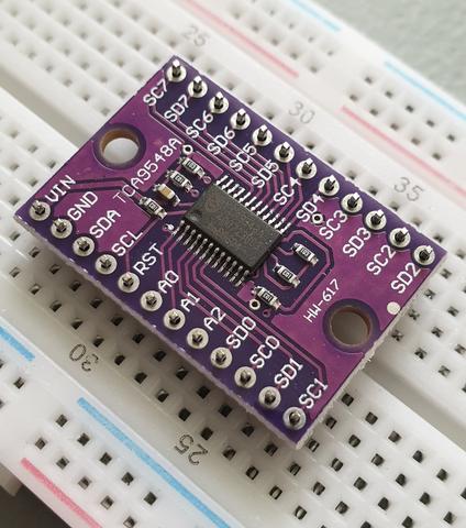
First, consider the TCA9548A itself. It is the gateway between your Arduino and eight separate I2C buses. You have a single bus on one side, connected to your Arduino.
On the other side of the TCA9548A, you have eight I2C buses, and only one of these can be connected to the Arduino at a time. For example (from the data sheet):
The TCA9548 can operate on voltages between 1.8 and 5V DC… and operate with devices that have operating voltages between 1.8 and 5V DC. This is very convenient, as (for example) you can use devices made for 3.3V operation with 5V Arduinos, or vice versa. Awesome. So let’s get started.
The breakout board includes inline header pins, which are not soldered to the board. So you need to do that. An easy way to line up the pins properly is to drop them into a soldereless breadboard, as such:
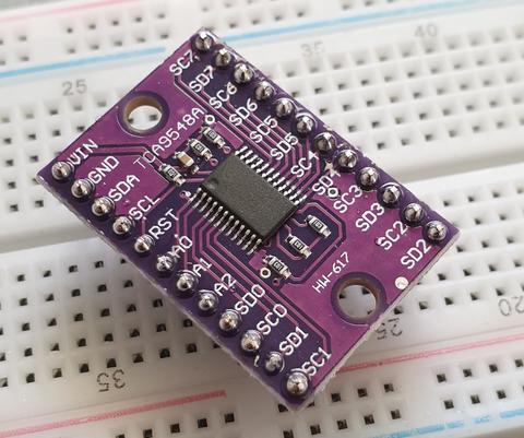
Then after a moment or two of soldering, you’re ready to use:
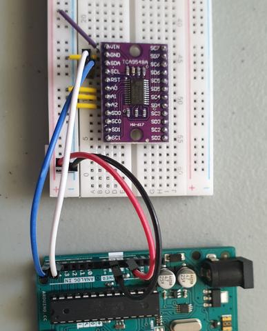
Next, insert your module into a solderless breadboard and wire it up as shown:
We are using the red and blue vertical strips on the breadboard as 5V and GND respectively. Finally, we connect the 5V and GND from the Arduino to the solderless breadboard, and A4/A5 to SDA/SCL respectively on the breakout board:
The electrical connections are as follows (Module — Arduino):
Vin to 5V
GND to GND
A0 to GND
A1 to GND
A2 to GND
SDA to A4
SCL to A5
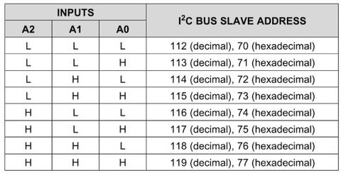
Next, we consider the I2C bus address for the TCA9548A. Using the wiring setup shown above, the address is set to 0x70. You only need to change this if one of your other devices also has an address of 0x70, as shown in the next step.
Changing the I2C address of the TCA9548A
The bus address of the TCA9548A is changed using the connections to the A0, A1 and A2 pins. By default in the tutorial we use 0x70, by wiring A0~A2 to GND (known as LOW). Using the table below, you can reconfigure to an address between 0x70 and 0x77 by matching the inputs to HIGH (5V) or LOW (GND):
Testing
Before we get too excited, now is a good time to test our wiring to ensure the Arduino can communicate with the TCA9548A. We’ll do this by running an I2C scanner sketch, which returns the bus address of a connected device.
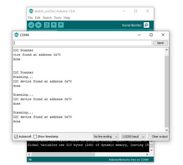
Copy and paste this sketch into your Arduino IDE and upload it to your board. Then, open the serial monitor and set the data rate to 115200. You should be presented with something like the following:
As you can see, our scanner returned an address of 0x70, which matches the wiring described in the bus address table mentioned earlier. If you did not find success, unplug the Arduino from the computer and double-check your wiring – then try again.
Controlling the bus selector
Using the TCA9548A is your sketch is not complex at all, it only requires one step before using your I2C device as normal. That extra step is to instruct the TCA9548A to use one of the eight buses that it controls.
To do this, we send a byte of data to the TCA9548A’s bus register which represents which of the eight buses we want to use. Each bit of the byte is used to turn the bus on or off, with the MSB (most significant bit) for bus 7, and the LSB (least significant bit) for bus 0.
For example, if you sent:
0b00000001 (in binary) or 0 in decimal
… this would activate bus zero.
Or if you sent:
0b00010000 (in binary)
… this would activate bus five.
Once you select a bus, the TCA9548A channels all data in and out of the bus to the Arduino on the selected bus. You only need to send the bus selection data when you want to change buses. We’ll demonstrate that later.
So to make life easier, we can use a little function to easily select the required bus:
void TCA9548A(uint8_t bus)
{
  Wire.beginTransmission(0x70);  // TCA9548A address is 0x70
  Wire.write(1 << bus);          // send byte to select bus
  Wire.endTransmission();
}
This function accepts a bus number and places a “1” in the TCA9548A’s bus register matching our requirements. Then, you simply slip this function right before needing to access a device on a particular I2C bus. For example, a device on bus 0:
TCA9548A(0);
… or a device on bus 6:
TCA9548A(6);
A quick note about pull-up resistors
You still need to use pull-up resistors on the eight I2C buses eminating from the TCA9548A. If you’re using an assembled module, such as our example devices – they will have the resistors – so don’t panic.
If not, check the data sheets for your devices to determine the appropriate pull-up resistors value. If this information isn’t available, try 10k0 resistors.
Controlling our first device
Our first example device is the tiny 0.49″ OLED display. It is has four connections, which are wired as follows (OLED — TCA9548A/Arduino):
GND to GND
Vcc to Arduino 3.3V
CL to TCA9548A SC0 (bus #0, clock pin)
DA to TCA9548A SD1 (bus #0, data pin)
The OLED runs from 3.3V, so that’s why we’re powering it directly from the Arduino’s 3.3V pin.
Now, copy and upload this sketch to your Arduino, and after a moment the OLED will display some numbers counting down in various amounts:
So how did that work? We inserted out bus selection function at line 9 of the sketch, then called the function in at line 26 to tell the TCA9548A that we wanted to use I2C bus zero. Then the rest of the sketch used the OLED as normal.
Controlling two devices
Let’s add another device, a BMP180 barometric pressure sensor module. We’ll connect this to I2C bus number seven on the TCA5948A. There are four connections, which are wired as follows (BMP180 — TCA9548A/Arduino):
GND to GND
Vcc to Arduino 3.3V
CL to TCA9548A SC0 (bus #7, clock pin)
DA to TCA9548A SD1 (bus #7, data pin)
Now, copy and upload this sketch to the Arduino, and after a moment the OLED will display the ambient temperature from the BMP180 in whole degrees Celsius. This is demonstrated in the following video (finger is placed on the BMP180 for force a rise in temperature):
So how did that work? We set up the libraries and required code for the OLED, BMP180 and TCA5948A as usual.
We need to intialise the BMP180, so this is done at line 29 – where we select the I2C bus 7 before initiating the BMP180.
The the sketch operates. On line 40 we again request I2C bus 7 from the TCA9548A, then get the temperature from the BMP180.
On line 44 we request I2C bus 0 from the TCA9548A, and then display the temperature on the OLED. Then repeat.
A quick note about the reset pin
More advanced users will be happy to know they can reset the TCA9548A status, to recover from a bus-fault condition. To do this, simply drop the RESET pin LOW (that is, connect it to GND).
Where to from here?
You can now understand through our worked example how easy it is to use the TCA9548A and access eight secondary I2C buses through the one bus from your Arduino. Don’t forget that the TCA9548A also does double-duty as a level converter, thereby increasing its value to you.
And that’s all for now. This post brought to you by pmdway.com – everything for makers and electronics enthusiasts, with free delivery worldwide.
To keep up to date with new posts at tronixstuff.com, please subscribe to the mailing list in the box on the right, or follow us on twitter @tronixstuff.
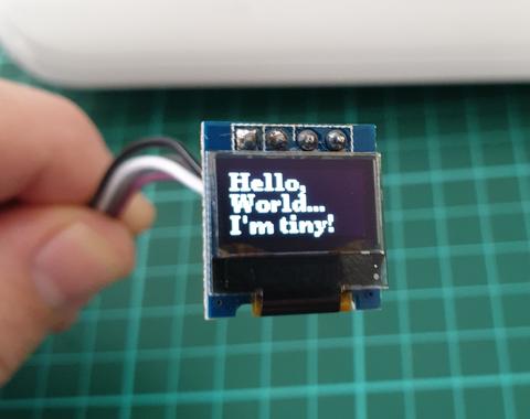
In this article we look at the tiny 0.49″ 64×32 graphic OLED from PMD Way. It is a compact and useful display, that only requires a small amount of time to get working with your Arduino or compatible board.
The purpose of this guide is to get your display successfully operating with your Arduino, so you can move forward and experiment and explore further types of operation with the display.
This includes installing the Arduino library, making a succesful board connection and running a demonstration sketch. So let’s get started!
Connecting the display to your Arduino
The display uses the I2C data bus for communication, and is a 5V and 3.3V-tolerant board.
Arduino Uno to Display
GND ---- GND (GND)

5V/3.3V- Vcc (power supply, can be 3.3V or 5V)

A5 ----- SCL (I2C bus clock)

A4 ----- SDA (I2C bus data)
I2C pinouts vary for other boards. Arduino Leonard uses D2/D3 for SDA and SCL or the separate pins to the left of D13. Arduino Mega uses D20/D21 for SDA and SCL. If you can’t find your I2C pins on other boards, email admin at tronixstuff dot com for assistance.
Installing the Arduino library
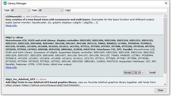
To install the library – simply open the Arduino IDE and select Manage Libraries… from the Tools menu. Enter “u8g2” in the search box, and after a moment it should appear in the results as shown in the image below. Click on the library then click “Install”:
After a moment the library will be installed and you can close that box.
Now it’s time to check everything necessary is working. Open a new sketch in the IDE, then copy and paste the following sketch into the IDE (you may find the “view raw” link at the end useful):
Your display should go through the demonstration of various font sizes and so on as shown in the video below:
You can see how we’ve used a different font in the sketch – at lines 19, 30 and 38. The list of fonts included with the library are provided at https://github.com/olikraus/u8g2/wiki/fntlistall.
Note that the initial location for each line of text (for example in line 20):
u8g2.drawStr(0, 5, "Hello,"); // write something to the internal memory
The x and y coordinates (0,5) are for the bottom-left of the first character.
If you want to display values, not text – such as integers, use:
u8g2.print();
… an example of which is show around line 49 in the example sketch.
Where to from here?
Now it’s time for you to explore the library reference guide which explains all the various functions available to create text and graphics on the display, as well as the fonts and so on. These can all be found on the right-hand side of the driver wiki page.
And that’s all for now. This post brought to you by pmdway.com – everything for makers and electronics enthusiasts, with free delivery worldwide.
To keep up to date with new posts at tronixstuff.com, please subscribe to the mailing list in the box on the right, or follow us on twitter @tronixstuff.
The purpose of this guide is to get your 0.96″ color LCD display successfully operating with your Arduino, so you can move forward and experiment and explore further types of operation with the display. This includes installing the Arduino library, making a succesful board connection and running a demonstration sketch.
Although you can use the display with an Arduino Uno or other boad with an ATmega328-series microcontroller – this isn’t recommended for especially large projects. The library eats up a fair amount of flash memory – around 60% in most cases.
So if you’re running larger projects we recommend using an Arduino Mega or Due-compatible board due to the increased amount of flash memory in their host microcontrollers.
Installing the Arduino library
So let’s get started. We’ll first install the Arduino library then move on to hardware connection and then operating the display.
(As the display uses the ST7735S controller IC, you may be tempted to use the default TFT library included with the Arduino IDE – however it isn’t that reliable. Instead, please follow the instructions below).
First – download the special Arduino library for your display and save it into your Downloads or a temp folder.
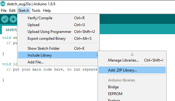
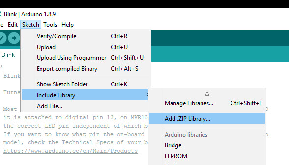
Next – open the Arduino IDE and select the Sketch > Include Library > Add .ZIP library option as shown below:
A dialog box will open – navigate to and select the zip file you downloaded earlier. After a moment or two the IDE will then install the library.
Please check that the library has been installed – to do this, select the Sketch > Include Library option in the IDE and scroll down the long menu until you see “ER-TFTM0.96-1” as shown below:
Once that has been successful, you can wire up your display.
Connecting the display to your Arduino
The display uses the SPI data bus for communication, and is a 3.3V board. You can use it with an Arduino or other 5V board as the logic is tolerant of higher voltages.
Arduino to Display
GND ----- GND (GND)

3.3V ---- Vcc (3.3V power supply)

D13 ----- SCL (SPI bus clock)

D11 ----- SDA (SPI bus data out from Arduino)

D10 ----- CS (SPI bus "Chip Select")

D9 ------ DC (Data instruction select pin)

D8 ------ RES (reset input)
If your Arduino has different pinouts than the Uno, locate the SPI pins for your board and modify as appropriate.
Demonstration sketch
Open a new sketch in the IDE, then copy and paste the following sketch into the IDE:
// https://pmdway.com/products/0-96-80-x-160-full-color-lcd-module#include<UTFT.h>// Declare which fonts we will be usingexternuint8_tSmallFont[];// Initialize display// Library only supports software SPI at this time//NOTE: support DUE , MEGA , UNO //SDI=11 SCL=13 /CS =10 /RST=8 D/C=9UTFTmyGLCD(ST7735S_4L_80160,11,13,10,8,9);//LCD: 4Line serial interface SDI SCL /CS /RST D/C NOTE:Only support DUE MEGA UNO// Declare which fonts we will be usingexternuint8_tBigFont[];intcolor=0;wordcolorlist[]={VGA_WHITE,VGA_BLACK,VGA_RED,VGA_BLUE,VGA_GREEN,VGA_FUCHSIA,VGA_YELLOW,VGA_AQUA};intbsize=4;voiddrawColorMarkerAndBrushSize(intcol){myGLCD.setColor(VGA_BLACK);myGLCD.fillRect(25,0,31,239);myGLCD.fillRect(myGLCD.getDisplayXSize()-31,161,myGLCD.getDisplayXSize()-1,191);myGLCD.setColor(VGA_WHITE);myGLCD.drawPixel(25,(col*30)+15);for(inti=1;i<7;i++)myGLCD.drawLine(25+i,((col*30)+15)-i,25+i,((col*30)+15)+i);if(color==1)myGLCD.setColor(VGA_WHITE);elsemyGLCD.setColor(colorlist[col]);if(bsize==1)myGLCD.drawPixel(myGLCD.getDisplayXSize()-15,177);elsemyGLCD.fillCircle(myGLCD.getDisplayXSize()-15,177,bsize);myGLCD.setColor(colorlist[col]);}voidsetup(){randomSeed(analogRead(0));// Setup the LCDmyGLCD.InitLCD();myGLCD.setFont(SmallFont);}voidloop(){intbuf[158];intx,x2;inty,y2;intr;// Clear the screen and draw the framemyGLCD.clrScr();myGLCD.setColor(255,0,0);myGLCD.fillRect(0,0,159,13);myGLCD.setColor(64,64,64);myGLCD.fillRect(0,114,159,127);myGLCD.setColor(255,255,255);myGLCD.setBackColor(255,0,0);myGLCD.print("pmdway.com.",CENTER,1);myGLCD.setBackColor(64,64,64);myGLCD.setColor(255,255,0);myGLCD.print("pmdway.com",LEFT,114);myGLCD.setColor(0,0,255);myGLCD.drawRect(0,13,159,113);// Draw crosshairsmyGLCD.setColor(0,0,255);myGLCD.setBackColor(0,0,0);myGLCD.drawLine(79,14,79,113);myGLCD.drawLine(1,63,158,63);myGLCD.setColor(0,0,255);myGLCD.drawLine(0,79,159,79);for(inti=9;i<150;i+=10)myGLCD.drawLine(i,61,i,65);for(inti=19;i<110;i+=10)myGLCD.drawLine(77,i,81,i);// Draw sin-, cos- and tan-lines myGLCD.setColor(0,255,255);myGLCD.print("Sin",5,15);for(inti=1;i<158;i++){myGLCD.drawPixel(i,63+(sin(((i*2.27)*3.14)/180)*40));}myGLCD.setColor(255,0,0);myGLCD.print("Cos",5,27);for(inti=1;i<158;i++){myGLCD.drawPixel(i,63+(cos(((i*2.27)*3.14)/180)*40));}myGLCD.setColor(255,255,0);myGLCD.print("Tan",5,39);for(inti=1;i<158;i++){myGLCD.drawPixel(i,63+(tan(((i*2.27)*3.14)/180)));}delay(2000);myGLCD.setColor(0,0,0);myGLCD.fillRect(1,14,158,113);myGLCD.setColor(0,0,255);myGLCD.setBackColor(0,0,0);myGLCD.drawLine(79,14,79,113);myGLCD.drawLine(1,63,158,63);myGLCD.setColor(0,0,255);myGLCD.drawLine(0,79,159,79);// Draw a moving sinewavex=1;for(inti=1;i<(158*20);i++){x++;if(x==159)x=1;if(i>159){if((x==79)||(buf[x-1]==63))myGLCD.setColor(0,0,255);elsemyGLCD.setColor(0,0,0);myGLCD.drawPixel(x,buf[x-1]);}myGLCD.setColor(0,255,255);y=63+(sin(((i*2.5)*3.14)/180)*(40-(i/100)));myGLCD.drawPixel(x,y);buf[x-1]=y;}delay(2000);myGLCD.setColor(0,0,0);myGLCD.fillRect(1,14,158,113);myGLCD.setColor(0,0,255);myGLCD.drawLine(0,79,159,79);// Draw some filled rectanglesfor(inti=1;i<6;i++){switch(i){case1:myGLCD.setColor(255,0,255);break;case2:myGLCD.setColor(255,0,0);break;case3:myGLCD.setColor(0,255,0);break;case4:myGLCD.setColor(0,0,255);break;case5:myGLCD.setColor(255,255,0);break;}myGLCD.fillRect(39+(i*10),23+(i*10),59+(i*10),43+(i*10));}delay(2000);myGLCD.setColor(0,0,0);myGLCD.fillRect(1,14,158,113);myGLCD.setColor(0,0,255);myGLCD.drawLine(0,79,159,79);// Draw some filled, rounded rectanglesfor(inti=1;i<6;i++){switch(i){case1:myGLCD.setColor(255,0,255);break;case2:myGLCD.setColor(255,0,0);break;case3:myGLCD.setColor(0,255,0);break;case4:myGLCD.setColor(0,0,255);break;case5:myGLCD.setColor(255,255,0);break;}myGLCD.fillRoundRect(99-(i*10),23+(i*10),119-(i*10),43+(i*10));}delay(2000);myGLCD.setColor(0,0,0);myGLCD.fillRect(1,14,158,113);myGLCD.setColor(0,0,255);myGLCD.drawLine(0,79,159,79);// Draw some filled circlesfor(inti=1;i<6;i++){switch(i){case1:myGLCD.setColor(255,0,255);break;case2:myGLCD.setColor(255,0,0);break;case3:myGLCD.setColor(0,255,0);break;case4:myGLCD.setColor(0,0,255);break;case5:myGLCD.setColor(255,255,0);break;}myGLCD.fillCircle(49+(i*10),33+(i*10),15);}delay(2000);myGLCD.setColor(0,0,0);myGLCD.fillRect(1,14,158,113);myGLCD.setColor(0,0,255);myGLCD.drawLine(0,79,159,79);// Draw some lines in a patternmyGLCD.setColor(255,0,0);for(inti=14;i<113;i+=5){myGLCD.drawLine(1,i,(i*1.44)-10,112);}myGLCD.setColor(255,0,0);for(inti=112;i>15;i-=5){myGLCD.drawLine(158,i,(i*1.44)-12,14);}myGLCD.setColor(0,255,255);for(inti=112;i>15;i-=5){myGLCD.drawLine(1,i,172-(i*1.44),14);}myGLCD.setColor(0,255,255);for(inti=15;i<112;i+=5){myGLCD.drawLine(158,i,171-(i*1.44),112);}delay(2000);myGLCD.setColor(0,0,0);myGLCD.fillRect(1,14,158,113);myGLCD.setColor(0,0,255);myGLCD.drawLine(0,79,159,79);// Draw some random circlesfor(inti=0;i<100;i++){myGLCD.setColor(random(255),random(255),random(255));x=22+random(116);y=35+random(57);r=random(20);myGLCD.drawCircle(x,y,r);}delay(2000);myGLCD.setColor(0,0,0);myGLCD.fillRect(1,14,158,113);myGLCD.setColor(0,0,255);myGLCD.drawLine(0,79,159,79);// Draw some random rectanglesfor(inti=0;i<100;i++){myGLCD.setColor(random(255),random(255),random(255));x=2+random(156);y=16+random(95);x2=2+random(156);y2=16+random(95);myGLCD.drawRect(x,y,x2,y2);}delay(2000);myGLCD.setColor(0,0,0);myGLCD.fillRect(1,14,158,113);myGLCD.setColor(0,0,255);myGLCD.drawLine(0,79,159,79);// Draw some random rounded rectanglesfor(inti=0;i<100;i++){myGLCD.setColor(random(255),random(255),random(255));x=2+random(156);y=16+random(95);x2=2+random(156);y2=16+random(95);myGLCD.drawRoundRect(x,y,x2,y2);}delay(2000);myGLCD.setColor(0,0,0);myGLCD.fillRect(1,14,158,113);myGLCD.setColor(0,0,255);myGLCD.drawLine(0,79,159,79);for(inti=0;i<100;i++){myGLCD.setColor(random(255),random(255),random(255));x=2+random(156);y=16+random(95);x2=2+random(156);y2=16+random(95);myGLCD.drawLine(x,y,x2,y2);}delay(2000);myGLCD.setColor(0,0,0);myGLCD.fillRect(1,14,158,113);myGLCD.setColor(0,0,255);myGLCD.drawLine(0,79,159,79);for(inti=0;i<5000;i++){myGLCD.setColor(random(255),random(255),random(255));myGLCD.drawPixel(2+random(156),16+random(95));}delay(2000);myGLCD.fillScr(0,0,255);myGLCD.setColor(255,0,0);myGLCD.fillRoundRect(10,17,149,72);myGLCD.setColor(255,255,255);myGLCD.setBackColor(255,0,0);myGLCD.print("That's it!",CENTER,20);myGLCD.print("Restarting in a",CENTER,45);myGLCD.print("few seconds...",CENTER,57);myGLCD.setColor(0,255,0);myGLCD.setBackColor(0,0,255);myGLCD.print("Runtime: (msecs)",CENTER,103);myGLCD.printNumI(millis(),CENTER,115);delay(5000);}
Once you’re confident with the physical connection, upload the sketch. It should result with output as shown in the video below:
Now that you have succesfully run the demonstration sketch – where to from here?
The library used is based on the uTFT library by Henning Karlsen. You can find all the drawing and other commands in the user manual – so download the pdf and enjoy creating interesting displays.
This post brought to you by pmdway.com – everything for makers and electronics enthusiasts, with free delivery worldwide.
To keep up to date with new posts at tronixstuff.com, please subscribe to the mailing list in the box on the right, or follow us on twitter @tronixstuff.
The purpose of this guide is to have an SSD1306-based OLED display successfully operating with your Arduino, so you can move forward and experiment and explore further types of operation with the display.
This includes installing the Arduino library, making a succesful board connection and running a demonstration sketch. So let’s get started!
Connecting the display to your Arduino
The display uses the I2C data bus for communication, and is a 5V and 3.3V-tolerant board.
Arduino Uno to Display
GND ---- GND (GND)

5V/3.3V- Vcc (power supply, can be 3.3V or 5V)

A5 ----- SCL (I2C bus clock)

A4 ----- SDA (I2C bus data)
I2C pinouts vary for other boards. Arduino Leonard uses D2/D3 for SDA and SCL or the separate pins to the left of D13. Arduino Mega uses D20/D21 for SDA and SCL. If you can’t find your I2C pins on other boards, ask your display supplier.
Installing the Arduino library
To install the library – simply open the Arduino IDE and select Manage Libraries… from the Tools menu. Enter “u8g2” in the search box, and after a moment it should appear in the results as shown in the image below. Click on the library then click “Install”:
After a moment the library will be installed and you can close that box.
Now it’s time to check everything necessary is working. Open a new sketch in the IDE, then copy and paste the following sketch into the IDE:
// Display > https://pmdway.com/products/0-96-128-64-graphic-oled-displays-i2c-or-spi-various-colors#include<Arduino.h>#include<U8x8lib.h>#ifdefU8X8_HAVE_HW_SPI#include<SPI.h>#endif#ifdefU8X8_HAVE_HW_I2C#include<Wire.h>#endifU8X8_SSD1306_128X64_NONAME_HW_I2Cu8x8(/* reset=*/U8X8_PIN_NONE);/* This example will probably not work with the SSD1606, because of the internal buffer swapping*/voidsetup(void){/* U8g2 Project: KS0108 Test Board *///pinMode(16, OUTPUT);//digitalWrite(16, 0); /* U8g2 Project: Pax Instruments Shield: Enable Backlight *///pinMode(6, OUTPUT);//digitalWrite(6, 0); u8x8.begin();//u8x8.setFlipMode(1);}voidpre(void){u8x8.setFont(u8x8_font_amstrad_cpc_extended_f);u8x8.clear();u8x8.inverse();u8x8.print(" U8x8 Library ");u8x8.setFont(u8x8_font_chroma48medium8_r);u8x8.noInverse();u8x8.setCursor(0,1);}voiddraw_bar(uint8_tc,uint8_tis_inverse){uint8_tr;u8x8.setInverseFont(is_inverse);for(r=0;r<u8x8.getRows();r++){u8x8.setCursor(c,r);u8x8.print(" ");}}voiddraw_ascii_row(uint8_tr,intstart){inta;uint8_tc;for(c=0;c<u8x8.getCols();c++){u8x8.setCursor(c,r);a=start+c;if(a<=255)u8x8.write(a);}}voidloop(void){inti;uint8_tc,r,d;pre();u8x8.print("github.com/");u8x8.setCursor(0,2);u8x8.print("olikraus/u8g2");delay(2000);u8x8.setCursor(0,3);u8x8.print("Tile size:");u8x8.print((int)u8x8.getCols());u8x8.print("x");u8x8.print((int)u8x8.getRows());delay(2000);pre();for(i=19;i>0;i--){u8x8.setCursor(3,2);u8x8.print(i);u8x8.print(" ");delay(150);}draw_bar(0,1);for(c=1;c<u8x8.getCols();c++){draw_bar(c,1);draw_bar(c-1,0);delay(50);}draw_bar(u8x8.getCols()-1,0);pre();u8x8.setFont(u8x8_font_amstrad_cpc_extended_f);for(d=0;d<8;d++){for(r=1;r<u8x8.getRows();r++){draw_ascii_row(r,(r-1+d)*u8x8.getCols()+32);}delay(400);}draw_bar(u8x8.getCols()-1,1);for(c=u8x8.getCols()-1;c>0;c--){draw_bar(c-1,1);draw_bar(c,0);delay(50);}draw_bar(0,0);pre();u8x8.drawString(0,2,"Small");u8x8.draw2x2String(0,5,"Scale Up");delay(3000);pre();u8x8.drawString(0,2,"Small");u8x8.setFont(u8x8_font_px437wyse700b_2x2_r);u8x8.drawString(0,5,"2x2 Font");delay(3000);pre();u8x8.drawString(0,1,"3x6 Font");u8x8.setFont(u8x8_font_inb33_3x6_n);for(i=0;i<100;i++){u8x8.setCursor(0,2);u8x8.print(i);// Arduino Print functiondelay(10);}for(i=0;i<100;i++){u8x8.drawString(0,2,u8x8_u16toa(i,5));// U8g2 Build-In functionsdelay(10);}pre();u8x8.drawString(0,2,"Weather");u8x8.setFont(u8x8_font_open_iconic_weather_4x4);for(c=0;c<6;c++){u8x8.drawGlyph(0,4,'@'+c);delay(300);}pre();u8x8.print("print \\n\n");delay(500);u8x8.println("println");delay(500);u8x8.println("done");delay(1500);pre();u8x8.fillDisplay();for(r=0;r<u8x8.getRows();r++){u8x8.clearLine(r);delay(100);}delay(1000);}
Your display should go through the demonstration of various things as shown in the video below:
If the display did not work – you may need to manually set the I2C bus address. To do this, wire up your OLED then run this sketch (open the serial monitor for results). It’s an I2C scanner tool that will return the I2C bus display.
Then use the following line in void setup():
u8x8.setI2CAddress(address)
Replace u8x8 with your display reference, and address with the I2C bus address (for example. 0x17).
Moving on…
By now you have an idea of what is possible with these great-value displays.
Now your display is connected and working, it’s time to delve deeper into the library and the various modes of operations. There are three, and they are described in the library documentation – click here to review them.
Whenever you use one of the three modes mentioned above, you need to use one of the following constructor lines:
U8G2_SSD1306_128X64_NONAME_F_HW_I2C u8g2(U8G2_R0, /* reset=*/ U8X8_PIN_NONE); // full buffer mode
U8X8_SSD1306_128X64_NONAME_HW_I2C u8x8(/* reset=*/ U8X8_PIN_NONE); // 8x8 character mode
Match the mode you wish to use with one of the constructors above. For example, in the demonstration sketch you ran earlier, we used the 8×8 character mode constructor in line 14.
Where to from here?
Now it’s time for you to explore the library reference guide which explains all the various functions available to create text and graphics on the display, as well as the fonts and so on. These can all be found on the right-hand side of the driver wiki page.
This post brought to you by pmdway.com – everything for makers and electronics enthusiasts, with free delivery worldwide.
To keep up to date with new posts at tronixstuff.com, please subscribe to the mailing list in the box on the right, or follow us on twitter @tronixstuff.
In this tutorial we look at how to use the neat LED Real Time Clock Temperature Sensor Shield for Arduino from PMD Way. That’s a bit of a mouthful, however the shield does offer the following:
four digit, seven-segment LED display
DS1307 real-time clock IC
three buttons
four LEDs
a active buzzer
a light-dependent resistor (LDR)
and a thermistor for measuring ambient temperature
The shield also arrives fully-assembled , so you can just plug it into your Arduino Uno or compatible board. Neat, beginners will love that. So let’s get started, by showing how each function can be used – then some example projects. In no particular order…
The buzzer
A high-pitched active buzzer is connected to digital pin D6 – which can be turned on and off with a simple digitalWrite() function. So let’s do that now, for example:
voidsetup(){// buzzer on digital pin 6pinMode(6,OUTPUT);}// the loop function runs over and over again forevervoidloop(){digitalWrite(6,HIGH);// turn the buzzer on (HIGH is the voltage level)delay(1000);// wait for a seconddigitalWrite(6,LOW);// turn the buzzer off by making the voltage LOWdelay(1000);// wait for a second}
If there is a white sticker over your buzzer, remove it before uploading the sketch. Now for a quick video demonstration. Turn down your volume before playback.
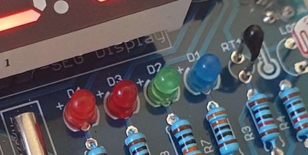
The LEDs
Our shield has four LEDs, as shown below:
They’re labelled D1 through to D4, with D1 on the right-hand side. They are wired to digital outputs D2, D3, D4 and D5 respectively. Again, they can be used with digitalWrite() – so let’s do that now with a quick demonstration of some blinky goodness. Our sketch turns the LEDs on and off in sequential order. You can change the delay by altering the variable x:
voidsetup(){// initialize digital pin LED_BUILTIN as an output.pinMode(2,OUTPUT);// LED 1pinMode(3,OUTPUT);// LED 2pinMode(4,OUTPUT);// LED 3pinMode(5,OUTPUT);// LED 4}intx=200;voidloop(){digitalWrite(2,HIGH);// turn on LED1delay(x);digitalWrite(2,LOW);// turn off LED1. Process repeats for the other three LEDsdigitalWrite(3,HIGH);delay(x);digitalWrite(3,LOW);digitalWrite(4,HIGH);delay(x);digitalWrite(4,LOW);digitalWrite(5,HIGH);delay(x);digitalWrite(5,LOW);}
And in action:
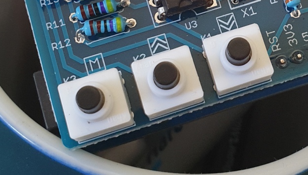
The Buttons
It is now time to pay attention to the three large buttons on the bottom-left of the shield. They look imposing however are just normal buttons, and from right-to-left are connected to digital pins D9, D10 and D11:
They are, however, wired without external pull-up or pull-down resistors so when initialising them in your Arduino sketch you need to activate the digital input’s internal pull-up resistor inside the microcontroller using:
pinMode(pin, INPUT_PULLUP);
Due to this, buttons are by default HIGH when not pressed. So when you press a button, they return LOW. The following sketch demonstrates the use of the buttons by lighting LEDs when pressed:
voidsetup(){// initalise digital pins for LEDs as outputspinMode(2,OUTPUT);// LED 1pinMode(3,OUTPUT);// LED 2pinMode(4,OUTPUT);// LED 3// initalise digital pins for buttons as inputs// and initialise internal pullupspinMode(9,INPUT_PULLUP);// button K1pinMode(10,INPUT_PULLUP);// button K2pinMode(11,INPUT_PULLUP);// button K3}voidloop(){if(digitalRead(9)==LOW){digitalWrite(2,HIGH);delay(10);digitalWrite(2,LOW);}if(digitalRead(10)==LOW){digitalWrite(3,HIGH);delay(10);digitalWrite(3,LOW);}if(digitalRead(11)==LOW){digitalWrite(4,HIGH);delay(10);digitalWrite(4,LOW);}}
You can see these in action via the following video:
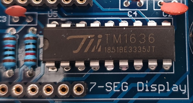
The Numerical LED Display
Our shield has a nice red four-digit, seven-segment LED clock display. We call it a clock display as there are colon LEDs between the second and third digit, just as a digital clock would usually have:
The TM1636 itself is an interesting part, so we’ll explain that in a separate tutorial in the near future. For now, back to the shield.
To control the LED display we need to install an Arduino library. In fact the shield needs four, so you can install them all at once now. Download the .zip file from here. Then expand that into your local download directory – it contains four library folders. You can then install them one at a time using the Arduino IDE’s Sketch > Include library > Add .zip library… command:
The supplied library offers five functions used to control the display.
.num(x);
…this displays a positive integer (whole number) between 0 and 9999.
.display(p,d);
… this shows a digit d in location p (locations from left to right are 3, 2, 1, 0)
.time(h,m)
… this is used to display time data (hours, minutes) easily. h is hours, m is minutes
.pointOn();
.pointOff();
… these turn the colon on … and off. And finally:
.clear();
… which clears the display to all off. At the start of the sketch, we need to use the library and initiate the instance of the display by inserting the following lines:
#include <TTSDisplay.h>
TTSDisplay rtcshield;
Don’t panic – the following sketch demonstrates the five functions described above:
#include<TTSDisplay.h>TTSDisplayrtcshield;inta=0;intb=0;voidsetup(){}voidloop(){// display some numbersfor(a=4921;a<5101;a++){rtcshield.num(a);delay(10);}// clear displayrtcshield.clear();// display individual digitsfor(a=3;a>=0;--a){rtcshield.display(a,a);delay(1000);rtcshield.clear();}for(a=3;a>=0;--a){rtcshield.display(a,a);delay(1000);rtcshield.clear();}// turn the colon and offfor(a=0;a<5;a++){rtcshield.pointOn();delay(500);rtcshield.pointOff();delay(500);}// demo the time display functionrtcshield.pointOn();rtcshield.time(11,57);delay(1000);rtcshield.time(11,58);delay(1000);rtcshield.time(11,59);delay(1000);rtcshield.time(12,00);delay(1000);}
And you can see it in action through the video below:
The LDR (Light Dependent Resistor)
LDRs are useful for giving basic light level measurements, and our shield has one connected to analog input pin A1. It’s the two-legged item with the squiggle on top as shown below:
The resistance of LDRs change with light levels – the greater the light, the less the resistance. Thus by measuring the voltage of a current through the LDR with an analog input pin – you can get a numerical value proportional to the ambient light level. And that’s just what the following sketch does:
#include<TTSDisplay.h>TTSDisplayrtcshield;inta=0;voidsetup(){}voidloop(){// read value of analog inputa=analogRead(A1);// show value on displayrtcshield.num(a);delay(100);}
The Thermistor
A thermistor is a resistor whose resistance is relative to the ambient temperature. As the temperature increases, their resistance decreases. It’s the black part to the left of the LDR in the image below:
We can use this relationship between temperature and resistance to determine the ambient temperature. To keep things simple we won’t go into the theory – instead, just show you how to get a reading.
The thermistor circuit on our shield has the output connected to analog input zero, and we can use the library installed earlier to take care of the mathematics. Which just leaves us with the functions.
At the start of the sketch, we need to use the library and initiate the instance of the thermistor by inserting the following lines:
#include <TTSTemp.h>
TTSTemp temp;
… then use the following which returns a positive integer containing the temperature (so no freezing cold environments):
.get();
For our example, we’ll get the temperature and show it on the numerical display:
And our thermometer in action. No video this time… a nice 24 degrees C in the office:
The Real-Time Clock
Our shield is fitted with a DS1307 real-time clock IC circuit and backup battery holder. If you insert a CR1220 battery, the RTC will remember the settings even if you remove the shield from the Arduino or if there’s a power blackout, board reset etc:
The DS1307 is incredibly popular and used in many projects and found on many inexpensive breakout boards. We have a separate tutorial on how to use the DS1307, so instead of repeating ourselves – please visit our specific DS1307 Arduino tutorial, then return when finished.
Where to from here?
We can image there are many practical uses for this shield, which will not only improve your Arduino coding skills but also have some useful applications. An example is given below, that you can use for learning or fun.
Temperature Alarm
This projects turns the shield into a temperature monitor – you can select a lower and upper temperature, and if the temperature goes outside that range the buzzer can sound until you press it.
Here’s the sketch:
#include<TTSDisplay.h>#include<TTSTemp.h>TTSTemptemp;TTSDisplayrtcshield;booleanalarmOnOff=false;inthighTemp=40;intlowTemp=10;intcurrentTemp;voidLEDsoff(){// function to turn all alarm high/low LEDs offdigitalWrite(2,LOW);digitalWrite(4,LOW);}voidsetup(){// initalise digital pins for LEDs and buzzer as outputspinMode(2,OUTPUT);// LED 1pinMode(3,OUTPUT);// LED 2pinMode(4,OUTPUT);// LED 3pinMode(5,OUTPUT);// LED 4pinMode(6,OUTPUT);// buzzer// initalise digital pins for buttons as inputs// and initialise internal pullupspinMode(9,INPUT_PULLUP);// button K1pinMode(10,INPUT_PULLUP);// button K2pinMode(11,INPUT_PULLUP);// button K3}voidloop(){// get current temperaturecurrentTemp=temp.get();// if current temperature is within set limts// show temperature on displayif(currentTemp>=lowTemp||currentTemp<=highTemp)// if ambient temperature is less than high boundary// OR if ambient temperature is grater than low boundary// all is well{LEDsoff();// turn off LEDsrtcshield.num(currentTemp);}// if current temperature is above set high bounday, show red LED and// show temperature on display// turn on buzzer if alarm is set to on (button K3)if(currentTemp>highTemp){LEDsoff();// turn off LEDsdigitalWrite(4,HIGH);// turn on red LEDrtcshield.num(currentTemp);if(alarmOnOff==true){digitalWrite(6,HIGH);// buzzer on }}}// if current temperature is below set lower boundary, show blue LED and// show temperature on display// turn on buzzer if alarm is set to on (button K3)if(currentTemp<lowTemp){LEDsoff();// turn off LEDsdigitalWrite(2,HIGH);// turn on blue LEDrtcshield.num(currentTemp);if(alarmOnOff==true){digitalWrite(6,HIGH);// buzzer on }}}// --------turn alarm on or off-----------------------------------------------------if(digitalRead(11)==LOW)// turn alarm on or off{alarmOnOff=!alarmOnOff;if(alarmOnOff==0){digitalWrite(6,LOW);// turn off buzzerdigitalWrite(5,LOW);// turn off alarm on LED}// if alarm is set to on, turn LED on to indicate thisif(alarmOnOff==1){digitalWrite(5,HIGH);}delay(300);// software debounce}// --------set low temperature------------------------------------------------------if(digitalRead(10)==LOW)// set low temperature. If temp falls below this value, activate alarm{// clear display and turn on blue LED to indicate user is setting lower boundaryrtcshield.clear();digitalWrite(2,HIGH);// turn on blue LEDrtcshield.num(lowTemp);// user can press buttons K2 and K1 to decrease/increase lower boundary.// once user presses button K3, lower boundary is locked in and unit goes// back to normal statewhile(digitalRead(11)!=LOW)// repeat the following code until the user presses button K3{if(digitalRead(10)==LOW)// if button K2 pressed{--lowTemp;// subtract one from lower boundary// display new value. If this falls below zero, won't display. You can add checks for this yourself :)rtcshield.num(lowTemp);}if(digitalRead(9)==LOW)// if button K3 pressed{lowTemp++;// add one to lower boundary// display new value. If this exceeds 9999, won't display. You can add checks for this yourself :)rtcshield.num(lowTemp);}delay(300);// for switch debounce}digitalWrite(2,LOW);// turn off blue LED}// --------set high temperature-----------------------------------------------------if(digitalRead(9)==LOW)// set high temperature. If temp exceeds this value, activate alarm{// clear display and turn on red LED to indicate user is setting lower boundaryrtcshield.clear();digitalWrite(4,HIGH);// turn on red LEDrtcshield.num(highTemp);// user can press buttons K2 and K1 to decrease/increase upper boundary.// once user presses button K3, upper boundary is locked in and unit goes// back to normal statewhile(digitalRead(11)!=LOW)// repeat the following code until the user presses button K3{if(digitalRead(10)==LOW)// if button K2 pressed{--highTemp;// subtract one from upper boundary// display new value. If this falls below zero, won't display. You can add checks for this yourself :)rtcshield.num(highTemp);}if(digitalRead(9)==LOW)// if button K3 pressed{highTemp++;// add one to upper boundary// display new value. If this exceeds 9999, won't display. You can add checks for this yourself :)rtcshield.num(highTemp);}delay(300);// for switch debounce}digitalWrite(4,LOW);// turn off red LED}}
Operating instructions:
To set lower temperature, – press button K2. Blue LED turns on. Use buttons K2 and K1 to select temperature, then press K3 to lock it in. Blue LED turns off.
To set upper temperature – press button K1. Red LED turns on. Use buttons K2 and K1 to select temperature, then press K3 to lock it in. Red LED turns off.
If temperature drops below lower or exceeds upper temperature, the blue or red LED will come on.
You can have the buzzer sound when the alarm activates – to do this, press K3. When the buzzer mode is on, LED D4 will be on. You can turn buzzer off after it activates by pressing K3.
Display will show ambient temperature during normal operation.
You can see this in action via the video below:
Conclusion
This is a fun and useful shield – especially for beginners. It offers a lot of fun and options without any difficult coding or soldering – it’s easy to find success with the shield and increase your motivation to learn more and make more.
You can be serious with a clock, or annoy people with the buzzer. And at the time of writing you can have one for US$14.95, delivered. So go forth and create something.
A little research has shown that this shield was based from a product by Seeed, who discontinued it from sale. I’d like to thank them for the library.
This post brought to you by pmdway.com – everything for makers and electronics enthusiasts, with free delivery worldwide.
To keep up to date with new posts at tronixstuff.com, please subscribe to the mailing list in the box on the right, or follow us on twitter @tronixstuff.
PROCEDIMENT: - Com a primer pas, hi ha que descarregar l'Arduino amb aquest link: https://www.arduino.cc/en/Main/Software. Si el tens ja descarregat, no fa falta utilitzar el link. - Necesites una matriu de leds 8x8, que la conectaràs a la placa Arduino que estarà conectada a l'ordinador amb un cable d'impressora. Aquesta matriu necesita un xip perquè amb només tres entrades no ens arriba per controlar els 64 leds, per tant, fiquem un xip que ens ajuda a controlar-les de manera que ho analitza i ho controla. - Una vegada connectat tot, només fa falta fer el còdig i encendre els leds que vols per a fer seqüències del que vulguis. PÀGINA WEB MOLT IMPORTANT: http://www.prometec.net/8x8-max7219/ PÀGINA IMPORTANT DE GITHUB: https://github.com/victorr09/Joc-of-the-lifeif
PROCEDIMENT: - Com a primer pas, hi ha que descarregar l'Arduino amb aquest link: https://www.arduino.cc/en/Main/Software. Si el tens ja descarregat, no fa falta utilitzar el link. - Necesites una matriu de leds 8x8, que la conectaràs a la placa Arduino que estarà conectada a l'ordinador amb un cable d'impressora. Aquesta matriu necesita un xip perquè amb només tres entrades no ens arriba per controlar els 64 leds, per tant, fiquem un xip que ens ajuda a controlar-les de manera que ho analitza i ho controla. - Una vegada connectat tot, només fa falta fer el còdig i encendre els leds que vols per a fer seqüències del que vulguis. PÀGINA WEB MOLT IMPORTANT: http://www.prometec.net/8x8-max7219/ PÀGINA IMPORTANT DE GITHUB: https://github.com/victorr09/Joc-of-the-lifeif
The Hummingbird by BirdBrain Technologies is an Arduino AtHeart microcontroller designed to enable beginners to create robots from craft materials. Hummingbird kits include LEDs, motors, and sensors that connect directly to the board. This eliminates the need for soldering or breadboarding and ensures that users have the parts they need to build their first robots. All of the components are reusable, so the same kit can be used to build many different robots.
In addition, the Hummingbird supports a variety of programming options, making it appropriate for beginning programmers as well as those who are more advanced. Some programming languages, such as Scratch and Snap!, can only be used when the board is connected to the computer. We will concentrate here on programming alternatives that enable users to upload a program onto the board’s Arduino.
Classrooms all over the world have used the Hummingbird from elementary to high school for projects ranging from Shakespeare dioramas to the physics of amusement park rides. In the following project, the BirdBrain Technologies team will show how they used the Hummingbird to build an automatic cat treat dispenser and demonstrate how the Hummingbird can be utilized to construct robots from everyday materials.
Building with the Hummingbird
Beginners can easily get started building Hummingbird robots with cardboard and craft materials. Motors, sensors, and LEDs can be connected directly to the Hummingbird board, and these elements can be added to the robot with hot glue. Hot glue peels off the components so that they can later be reused.
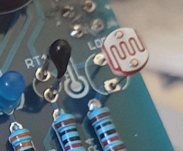
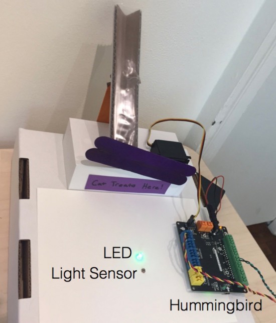
The example project uses one servo motor, one single color LED, and a light sensor. The dispenser consists of a servo motor attached to craft sticks that block the bottom of a chute containing cat treats. The position of the servo motor can be changed in software to release treats.
To receive a treat, the cat must cover a light sensor in front of the chute. When the cat covers the sensor, the servo motor briefly moves to open the chute and dispense a treat. The LED was included to show our test cat the location of the light sensor.
Programming with the Hummingbird
One unique feature of the Hummingbird is that it supports three different programming options for producing an Arduino program. These options provide steps of increasing difficulty to support learners as they transition from programming novices to Arduino experts.
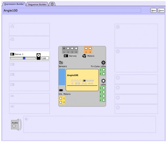
Beginners can start with the CREATE Lab Visual Programmer. This software option is based on storyboarding. Users can select the motors and LEDs that they are using on a schematic of the Hummingbird board. Then they can create expressions by using sliders to set the values of these outputs. The expression below sets a servo motor to 100°.
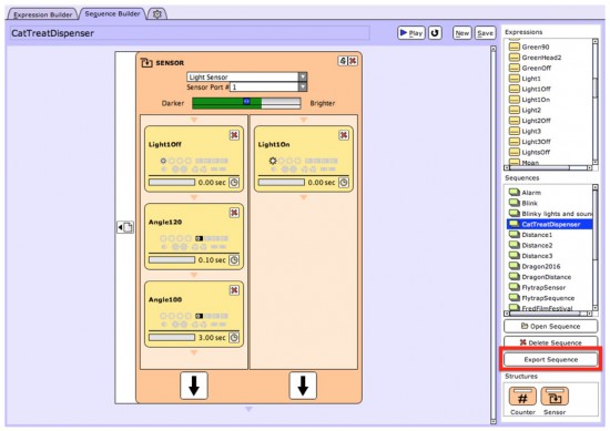
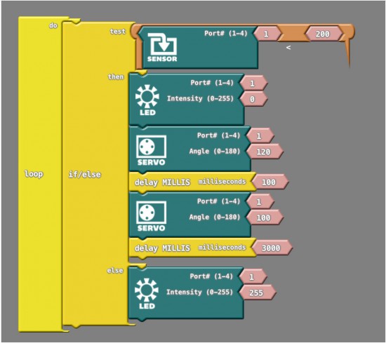
Expressions can be combined to create sequences. For example, the sequence below controls our automatic cat treat dispenser. This sequence is controlled by a sensor block. If the light level is low, the three expressions on the left are executed. If the light level is high, the three expressions on the right are executed. The user can then convert this sequence to an Arduino program by simply clicking the “Export Sequence” button (shown outlined in red). The Hummingbird can then be placed into Arduino mode and the program uploaded to the microcontroller.
Another option for beginners is ArduBlock, which provides a visual introduction to the Arduino language. The Hummingbird extension for ArduBlock includes a block for each Hummingbird component. A program in ArduBlock to control the treat dispenser is shown below. This program is equivalent to the CREATE Lab Visual Programmer sequence shown above.
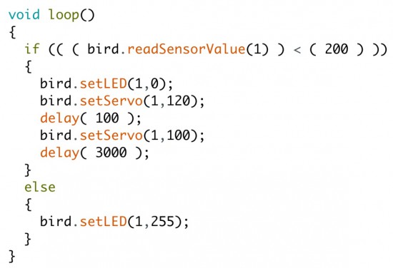
The Arduino code generated by this ArduBlock program is shown below. Individuals moving from the CREATE Lab Visual Programmer or ArduBlock to Arduino can start by modifying the generated code. For example, in the video we modified the commands inside the else to make the LED blink to attract the cat’s attention.
Once individuals are comfortable with the Arduino programming language, they can create more complex programs in Arduino. For instance, the video shows how we modified our robot and our code to incorporate three lights and three sensors. To get a treat, the cat must cover the sensor when the corresponding light is on.
The cat treat dispenser is only one example of a Hummingbird robot using the power of the Arduino at its core. The parts can be used and reused to construct an unlimited number of robots with low-cost materials such as cardboard, pipe cleaners, recycled materials, and even paper mache!
This robust DIN-rail mountable, Leonardo-compatible controller enables you to take your existing Arduino projects and swiftly transform them into permanent installations. The prototyping area and screw connectors allow you to install your own circuitry and reliably connect to accessories.
In the video below, Industruino co-founder Loic De Buck discusses these key features and more with Davide Gomba. (You can also find an extended version here.)
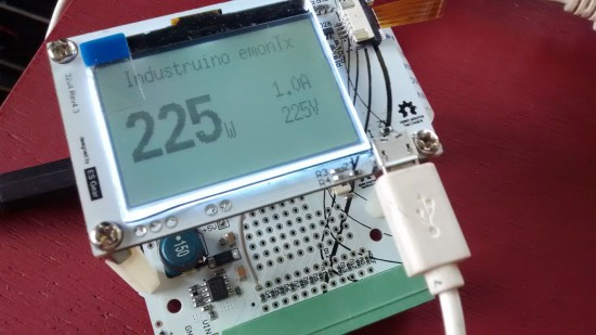
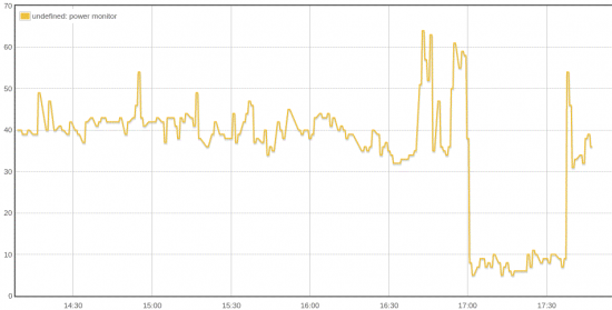
The team recently created an excellent tutorial showing how you to build an Arduino-based electricity consumption monitor with the Industruino PROTO platform. You can use it to measure AC power of your appliances, including a water cooker, TV, laptop charger, or anything else plugged into a wall socket. Alternatively, you can even use it in your electricity cabinet to evaluate the power consumption throughout your entire house (at least one phase).
The challenge is to measure an AC of a relatively high voltage (220-240V) with a direct current 5V Arduino MCU.
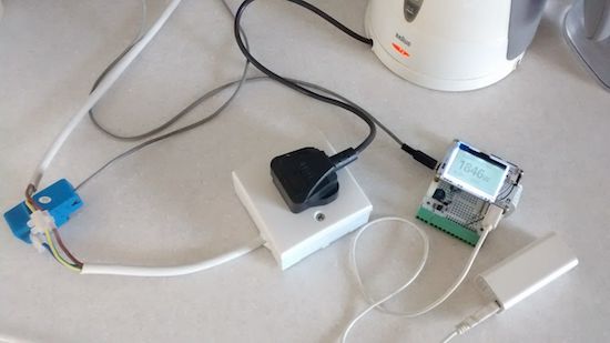
This may seem dangerous, but we will use a non-invasive Current Transformer (CT), so our Arduino remains galvanically isolated from the high voltage AC.
This prototype is based on the excellent open source project OpenEnergyMonitor. It uses parts of the its standard emonTx hardware and software to report the AC apparent power consumption, based on measurements of a Current Transformer as in the picture on the left. The original project also allows to measure 3 phase and/or real power, but for our prototype here we are only measuring the current of one phase, not its voltage which would require an AC/AC adaptor.
Planet Arduino is, or at the moment is wishing to become, an aggregation of public weblogs from around the world written by people who develop, play, think on Arduino platform and his son. The opinions expressed in those weblogs and hence this aggregation are those of the original authors. Entries on this page are owned by their authors. We do not edit, endorse or vouch for the contents of individual posts. For more information about Arduino please visit www.arduino.cc
You are currently browsing the archives for the tutorial category.

 [EbenKouao] uses a 3D-printable robotic gripper, base, and arm design as the foundation of his build. Hobby servos and a single NEMA 17 stepper take care of the moving, and the wiring and motor driving is all carefully explained. Gesture control is done by wearing an articulated glove upon which is mounted flex sensors and MPU6050 accelerometers. These sensors detect the wearer’s movements and turn them into motion commands, which in turn get sent wirelessly from the glove to the robotic arm with HC-05 Bluetooth modules. We really dig [EbenKouao]’s idea of mounting the glove sensors to this slick 3D-printed articulated gauntlet frame, but using a regular glove would work, too. The latest version of the Arduino code can be found on the project’s GitHub repository.