Hello readers
Today we continue with the series of articles on basic electronics with this continuation of the article about the resistor. Part one can be found here.
With regards to this article, it is only concerned with direct current (DC) circuits.
In this chapter we will examine how two or more resistors alter the flow of current in various ways. First of all, let’s recap what we learned in the previous chapter.
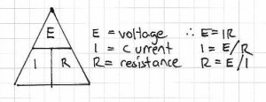
Ohm’s Law – the relationship between voltage, current and resistance:
Resistors in series:

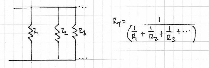
Resistors in parallel:

Dividing voltage with resistors:

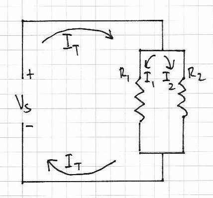
However the fun doesn’t stop there. As there is a relationship between voltage, current and resistance, we can also divide current with resistors. For now we will see how this works with two resistors. Please consider the following:

There is a balance between the two resistors with regards to the amount of current each can handle. The sum of the current through both resistors is the total current flowing through the circuit (It). The greater the resistance the less current will flow, and vice versa. That is, they are inversely proportional. And if R1 = R2, I1 = I2. Therefore, I1/I2=R2/R1 – or you can re-arrange the formula to find the other variables.
Here is an example of doing just that:
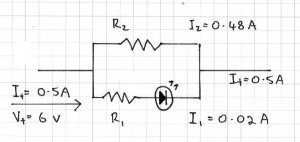
Our problem here – there is 6 volts DC at half an amp running from left to right, and we want to use an indicator LED in line with the current. However the LED only needs 2 volts at 20mA. What value should the resistors be?
First of all, let’s look at R1. It needs to change 6V to 2V, and only allow 20 mA to pass. R=E/A or R= 4 volts /0.2 amps = 200 ohms.
So R1 is 200 ohms. I1 is .02 A. Now we know that the total current is equal to I1+I2, so I2 will be 0.48A. That leaves us with the known unknown R2  We can re-arrange the formula R2/R1=I1/I2 to get R2 = (R1 x I1)/I2 – which gives us R2 of 8.3 ohms. Naturally this is a hypothetical, but I hope you now understand the relationship between the current through the resistors, and their actual resistance.

What we have just demonstrated in the problem above is an example of Kirchhoff’s current law (KCL). Gustav Kirchhoff was another amazing German physicist who worked on the understandings of electrical circuits amongst other things. More on GK here. His current law states that the amount of current entering a junction in a circuit must be equal to the sum of the currents leaving that junction. And not-coincidentally, there is also Kirchhoff’s voltage law (KVL) – the amount of voltage supplied to a circuit must equal the sum of the voltage drops in the circuit. These two laws also confirm one of the basic rules of physics – energy can not be created nor destroyed, only changed into different forms.
Here is a final way of wrapping up both KCL and KVL in one example:
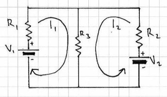
The current through R3 is equal to I1 + I2
Therefore, using Ohm’s law, V1 = R1I1 + (R3 x (I1+I2)) and V2 = R2I2 + (R3 x (I1+I2))
So with some basic algebra you can determine various unknowns. If algebra is your unknown, here is a page of links to free mathematics books, or have a poke around BetterWorldBooks.

There is also another way of finding the currents and voltages in a circuit with two or more sources of supply – the Superposition Theorem.
This involves removing all the sources of power (except for one) at a time, then using the rules of series and parallel resistors to calculate the current and voltage drops across the other components in the circuit. Then once you have all the values calculated with respect to each power source, you superimpose them (by adding them together algebraically) to find the voltages and currents when all the power sources are active. It sounds complex, but when you follow this example below, you will find it is quite simple. And a lot easier the th.. fourth time. Just be methodical and take care with your notes and calculations. So let’s go!
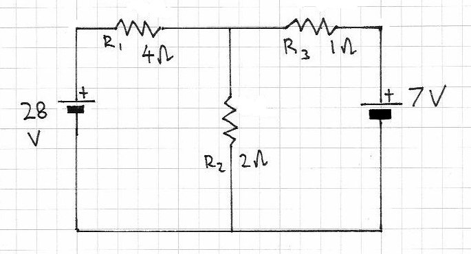
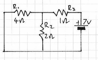
Consider this circuit:

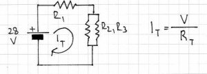
With the Superposition theorem we can determine the current flowing through the resistors, the voltage drops across them, and the direction in which the current flows. With our example circuit, the first thing to do is replace the 7V power source with a link:
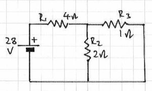
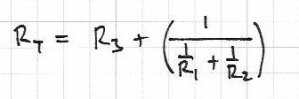
Next, we can determine the current values. We can use Ohm’s law for this. What we have is one power source, and R1 which is in series with R2/R3 (two parallel resistors). The total current in the circuit runs through R1, so calculate this first. It may help to think of the resistors in this way:

Then the formula for Rt is simple (above), and Rt is And now that we have a value for Rt, and the voltage (28V) the current is simple:
Which gives us a value of 6 amps for It. This current flows through R1, so the current for R1 is also 6 amps.
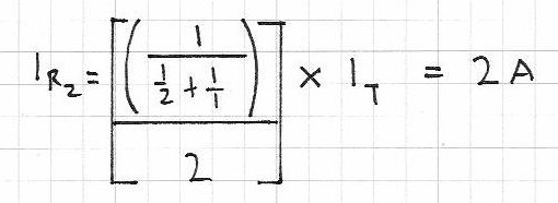
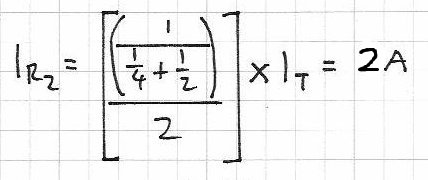
Next, the current through R2:

Using Kirchhoff’s Current Law, the current flowing through R2 and R2 will equal It. So, this is 4 amps.
At this point, note down what we know so far:
For source voltage 28V, Ir1 = 6A, Ir2 = 2A and Ir3 = 4A; R1=4 ohms, R2 = 2 ohms, R3 = 1 ohm.
Now – repeat the process by removing the 28V source and returning the 7V source, that is:

The total resistance Rt:
Gives us Rt = 2.3333 ohms (or 2 1/3);
Total current It will be 7 volts/Rt = 3 amps, so Ir3 = 3;

So Ir2 = 2A – therefore using KCL Ir1 = 3-2 = 1A.
So, with 7V source: Ir1 = 1A, Ir2 = 2A and Ir3 = 3A.
Next, we calculate the voltage drop across each resistor, again by using only one voltage source at a time. Using Ohm’s law, voltage = current x resistance.
For 28V:
Vr1 = 4 x 6 = 24V; Vr2 = 2 x 2 = 4V; Vr3 = 4 x 1 = 4V. Recall that R2 and R3 are in parallel, so the total voltage drop (24 + 4V) = 28 V which is the supply voltage.
Now, for 7V:
Vr1 = 4V, Vr2 = 4V, Vr3 = 3V.
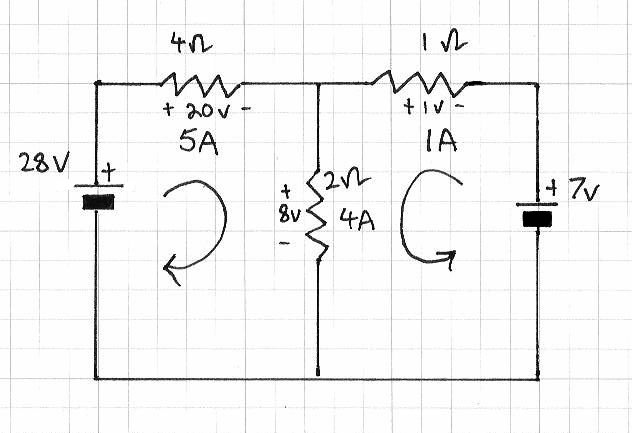
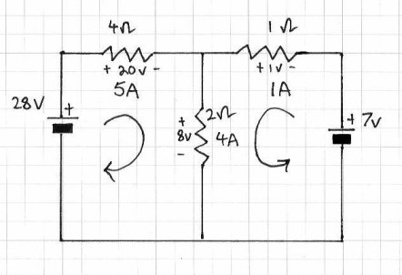
Phew – almost there. Now time to superimpose all the data onto the schematic to map out the current flow and voltage drops when both power sources are in use:

Finally, we combine the voltage values together, and the current values together. If the arrow is on the left, it is positive; on the right – negative. So:
Current – Ir1 = 6 – 1 = 5A; Ir2 = 2 +2 = 4A; Ir3 = 4-3 = 1A;
Voltage – Vr1 = 24 – 4 = 20V; Vr2 = 4 + 4 = 8V; Vr3 = 4 – 3 = 1V.
And with a deep breath we can proudly show the results of the investigation:
So that is how you use the Superposition theorem. However, there are some things you must take note of:
- the theorem only works for circuits that can be reduced to series and parallel combinations for each of the power sources
- only works when the equations are linear (i.e. straight line results, no powers, complex numbers, etc)
- will not work when resistance changes with temperature, current and so on
- all components must behave the same way regardless to polarity
- you cannot calculate power (watts) with this theorem, as it is non-linear.

Well that is enough for today. I hope you understood and can apply what we have discussed today. The final chapter on resistors can be found here.
As always, thank you for reading and I look forward to your comments and so on. Furthermore, don’t be shy in pointing out errors or places that could use improvement. Please subscribe using one of the methods at the top-right of this web page to receive updates on new posts. Or join our new Google Group.
Otherwise, have fun, be good to each other – and make something!
Notes: In writing this post, I used information from allaboutcircuits.com, plus information from various books by Forrest Mims III and “Practical Electronics Handbook” 4th ed., Ian Sinclair. And used a lot of paper working out the theorem for myself. Thank you!