Posts | Comments

Planet Arduino

Archive for the ‘555’ Category

It’s a little known secret that when the Hackaday writers gather in their secret underground bunker to work on our plans for world domination, we often take breaks to play our version of the corporate “Buzzword Bingo”, where paradigms are leveraged and meetings circle back to loop in offline stakeholders, or something like that. Our version, however, is “Comment Line Bingo”, and right in the middle of the card is the seemingly most common comment of all: “You should have used a 555,” or variations thereof.

So it was with vicious glee that we came across the Trollduino V1.0 by the deliciously named [Mild Lee Interested]. It’s the hardware answer to the common complaint, which we’ll grant is often justified. The beautiful part of this is that Trollduino occupies the same footprint as an Arduino Uno and is even pin-compatible with the microcontroller board, or at least sort of. The familiar line of components and connectors sprout from the left edge of the board, and headers for shields line the top and bottom edges too. “Sketches” are implemented in hardware, with jumpers and resistors and capacitors of various values plugged in to achieve all the marvelous configurations the indispensable timer chip can be used for. And extra points for the deliberately provocative use of Comic Sans in the silkscreen.

Hats off to [Lee] for a thoroughly satisfying troll, and a nice look at what the 555 chip can really do. If you want a more serious look at the 555, check out this 555 modeled on a breadboard, or dive into the story of the chip’s development.

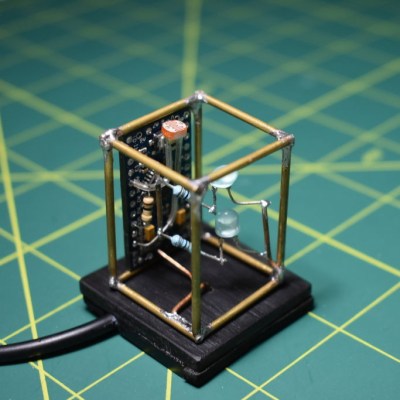
If you’re planning to get into circuit sculpture one of these days, it would probably be best to start with something small and simple, instead of trying to make a crazy light-up spaceship or something with a lot of curves on the first go. A small form factor doesn’t necessarily mean it can’t also be useful. Why not start by making a small automatic night light?

The circuit itself is quite simple, especially because it uses an Arduino. You could accomplish the same thing with a 555, but that’s going to complicate the circuit sculpture part of things a bit. As long as the ambient light level coming in from the light-dependent resistor is low enough, then the two LEDs will be lit.

We love the frosted acrylic panels that [akshar1101] connected together with what looks like right angle header pins. If you wanted to expose the electronics, localize the light diffusion with a little acrylic cover that slips over the LEDs. Check it out in the demo after the break.

There’s more than one way to build a glowing cuboid night light. The Rubik’s way, for instance.

Hardly a week goes by that some Hackaday post doesn’t elicit one of the following comments:

That’s stupid! Why use an Arduino when you could do the same thing with a 555?

And:

That’s stupid! Why use a bunch of parts when you can use an Arduino?

However, we rarely see those two comments on the same post. Until now. [ZHut] managed to bring these two worlds together by presenting how to make an Arduino blink an LED in conjunction with a 555 timer. We know, we know. It is hard to decide how to comment about this. You can consider it while you watch the video, below.

On the plus side, there probably is a use case for this. The LED will blink with absolutely no intervention from the Arduino. You could put the Arduino in deep sleep, if you wanted to and that LED will still blink. With a little work, you could probably adapt this idea to any number of circuits out of the 555 playbook, like a PWM generator, for example.

There’s almost nothing a 555 can’t do. If you want to see what’s under its expressionless face, this teardown is an interesting read. We just hope the comment section doesn’t overload like a Star Trek computer being asked by Captain Kirk to compute every digit of pi.


Filed under: Arduino Hacks
Jul
31

Various 1 Hz Oscillator Methods

1 hz, 555, 74hc14, astable, clock, clocks, digital, DS1307, DS3232, em406a, gps, logic, pps, timebase, tronixstuff, TTL, tutorial Comments Off on Various 1 Hz Oscillator Methods 

Introduction

During the fun and enjoyment of experimenting with electronics there will come a time when you need a nice 1 Hz oscillator to generate a square-wave signal to drive something in the circuit. On… off… on… off… for all sorts of things. Perhaps a metronome, to drive a TTL clock, blink some LEDs, or for more nefarious purposes. No matter what you need that magic 1 Hz for – there’s a variety of methods to generate it – some more expensive than others – and some more accurate than others.

A few of you may be thinking “pull out the Arduino” and yes, you could knock out a reasonable 1 Hz – however that’s fine for the bench, but wild overkill for embedding a project as a single purpose. So in this article we’ll run through three oscillator methods that can generate a 1 Hz signal (and other frequencies) using methods that vary in cost, accuracy and difficulty – and don’t rely on mains AC. That will be a topic for another day.

Using a 555 timer IC

You can solve this problem quite well for under a dollar with the 555, however the accuracy is going to heavily rely on having the correct values for the passive components. We’ll use the 555 in astable mode, and from a previous article here’s the circuit:

555 astable 1 Hz circuit

 And with a 5V power supply, here’s the result:

555-1

As you can see the cycle time isn’t the best, which can be attributed to the tolerance of the resistors and capacitor C1. A method to increase the accuracy would be to add small trimpots in series with the resistors (and reduce their value accordingly by the trimpot value) – then measure the output with a frequency counter (etc). whilst adjusting the trimpots. If you’re curious about not using C2, the result of doing so introduces some noise on the rising edge, for example:

555-2noise

So if you’ve no other option, or have the right values for the passives – the 555 can do the job. Or get yourself a 555 and experiment with it, there’s lots of fun to be had with it.

Using a GPS receiver module

A variety of GPS modules have a one pulse per second output (PPS) and this includes my well-worn EM406A module (as used in the Arduino tutorials):

EM406AGPS

With a little work you can turn that PPS output into a usable and incredibly accurate source of 1 Hz. As long as your GPS can receive a signal. In fact, this has been demonstrated in the April 2013 edition of Silicon Chip magazine, in their frequency counter timebase project. But I digress.

If you have an EM406A you most likely have the cable and if not, get one to save your sanity as the connector is quite non-standard. If you’re experimenting a breakout board will also be quite convenient, however you can make your own by just chopping off one end of the cable and soldering the required pins – for example:

EM406Abreakout

You will need access to pins 6, 5, 2 and 1. Looking at the socket on the GPS module, they are numbered 6 to 1 from left to right. Pin 6 is the PPS output, 5 is GND, 2 is for 5V and 1 is GND. Both the GNDs need to be connected together.

Before moving forward you’re probably curious about the pulse, and want to see it. Good idea! However the PPS signal is incredibly quick and has an amplitude of about 2.85 V. If you put a DSO on the PPS and GND output, you can see the pulses as shown below:

GPS-raw-PPS

 To find the length of the pulse, we had to really zoom in to a 2 uS timebase:

GPS-PPS-zoom

 Wow, that’s small. So a little external circuitry is required to convert that minuscule pulse into something more useful and friendly. We’ll increase the pulse length by using a “pulse stretcher”. To do this we make a monostable timer (“one shot”) with a 555. For around a half-second pulse we’ll use 47k0 for R1 and 10uF for C1. However this triggers on a low signal, so we first pass the PPS signal through a 74HC14 Schmitt inverter – a handy part which turns irregular signals into more sharply defined ones – and also inverts it which can then be used to trigger the monostable. Our circuit:

GPSPPS_schem

 and here’s the result – the PPS signal is shown with the matching “stretched” signal on the DSO:

GPS-1-Hz1

So if you’re a stickley for accuracy, or just want something different for portable or battery-powered applications, using the GPS is a relatively simple solution.

Using a Maxim DS1307/DS3232 real-time clock IC

Those of you with a microcontroller bent may have a Maxim DS1307 or DS3232. Apart from being pretty easy to use as a real-time clock, both of them have a programmable square wave output. Connection via your MCU’s I2C bus is quite easy, for example with the DS1307:

squarewave_schem

Using a DS3232 is equally as simple. We use a pre-built module with a similar schematic. Once you have either of them connected, the code is quite simple. For the DS1307 (bus address 0×68), write 0×07 then 0×11 to the I2C bus – or for the DS3232 (bus address is also 0×68) write 0x0E then 0×00. Finally, let’s see the 1 Hz on the DSO:

ds32321hz

Certainly not the cheapest method, however it gives you an excellent level of accuracy without the GPS.

Conclusion

By no means is this list exhaustive, however hopefully it was interesting and useful. If there’s any other methods you’d like to see demonstrated, leave a comment below and we’ll see what’s possible. And if you made it this far – check out my new book “Arduino Workshop” from No Starch Press.

LEDborder

In the meanwhile have fun and keep checking into tronixstuff.com. Why not follow things on twitterGoogle+, subscribe  for email updates or RSS using the links on the right-hand column? And join our friendly Google Group – dedicated to the projects and related items on this website. Sign up – it’s free, helpful to each other –  and we can all learn something.

The post Various 1 Hz Oscillator Methods appeared first on tronixstuff.

Hello readers!

Today we are going to examine the 4541 CMOS programmable timer IC. The main function of this chip is to act as a monostable timer. You are probably thinking one of two things – “what is a monostable timer?” or “why didn’t he use a 555 timer instead?”. A monostable timer is a timer that once activated sets an output high for a specified period of time, then stops waiting to be told to start again.  If you are not up to speed on the 555, have a look at my extensive review.

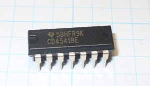
Although the 555 is cheap, easy to use and makes a popular timer, I have found that trying to get an exact time interval out of it somewhat difficult due to capacitor tolerance, so after some poking around found this IC and thought “Hmm – what have we here?”. So as always, let’s say hello:

As you can see this is a 14-pin package by Texas Instruments. It is also available in various surface-mount options. It is also currently available from FairchildNXP, ON Semi, and ST Micro. Note that this is a CMOS semiconductor, and that you should practice good anti-static precautions when handling it. Futhermore, when designing it into your circuit, don’t leave any pins floating – that is not connected to +5V or ground; unless specified by the data sheet. Here is the data sheet from ON Semiconductor.

This IC is interesting in that it contains a timer that can count to one of four values: 2^8, 2^10, 2^13, and 2^16. That is: 256, 1024, 8192 and 65536. With wiring you select which value to count to, and also the action to take whilst counting and once finished. This is quite easy, by connecting various pins to either GND or +5V. The following table from the data sheet details this:

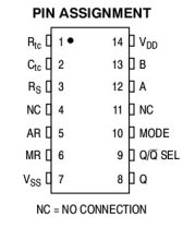
And here are the pinouts:

The speed of the counting (the frequency) is determined by a simple RC circuit. For more information on RC circuits, please visit this post. You can calculate the frequency using the following formula:

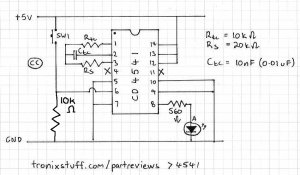
There are two external resistors used in the circuit – Rtc and Rs. Rs needs to be as close as possible to twice the value of Rtc. Try and use 1% tolerance metal-film resistors for accuracy, and a small value capacitor. Also remember to take note of the restrictions printed next to the formula above.

Before examining a demonstration circuit, I would like to show you how to calculate your timing duration. As you can see from the formula above, calculating the frequency is easy enough. Once you have a value for f, (the number of counts per second) divide this into the count value less one power you have wired the chip. That is, if you have wired the chip up for 2^16, divide your frequency into 2^15.

For example, my demonstration circuit has Rtc as 10k ohm, Ctc as 10 nF, and Rs as 20k ohm; and the chip is wired for 2^16 count. Remember to convert your values back to base units. So resistance in ohms, and capacitance in farads. Remember that 1 microfarad is 1×10⁻⁶ farads. So my frequency is:


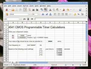
So my timing duration will be 2^15 divided by 4347.826 Hz (result from above) which is  7.536 seconds give or take a fraction of a second. To make these calculations easier, there is a spreadsheet you can download here. For example:

Here is my demonstration monstable circuit. Once the power has been turned on the counter starts, and once finished the LED is lit. Or if the circuit already has power, the reset button SW1 is pressed to start counting. You can see that pins 12 and 13 are high to enable counting to 2^16; pin 6 is low unless the button is pressed; and pin 9 is low which keeps the LED off while counting.


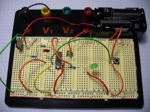
And my demonstration laid out (I really do make everything I write about):

Easily done. Although this IC has been around for a long time, and many other products have superseded it, the 4541 can still be quite useful. For example, an Arduino system might need to trigger a motor, light, or something to runfor a period of time whilst doing something else. Unfortunately (thankfully?) Arduino cannot multi-task sketches, so this is where the 4541 can be useful. You only need to use a digitalWrite() to send a pulse to pin 6 of your timer circuit, and then the sketch can carry on, while the timer does its job and turns something on or off for a specified period of time.

Well I hope you found this part review interesting, and helped you think of something new to make.

As always, thank you for reading and I look forward to your comments and so on. Furthermore, don’t be shy in pointing out errors or places that could use improvement. Please subscribe using one of the methods at the top-right of this web page to receive updates on new posts. Or join our new Google Group. High resolution photos are available on flickr.

Otherwise, have fun, be good to each other – and make something! :)

Notes: In writing this post, I used information from NXP and On Semiconductor. Thank you.


  • Newsletter

    Sign up for the PlanetArduino Newsletter, which delivers the most popular articles via e-mail to your inbox every week. Just fill in the information below and submit.

  • Like Us on Facebook