Posts | Comments

Planet Arduino

Archive for the ‘photo’ Category

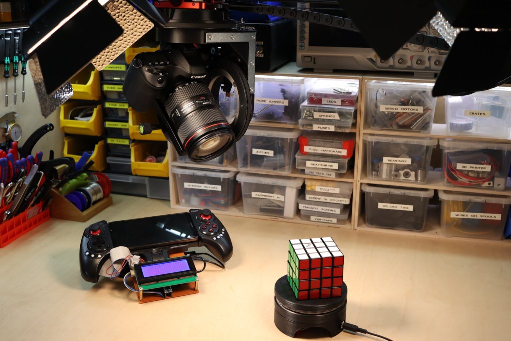
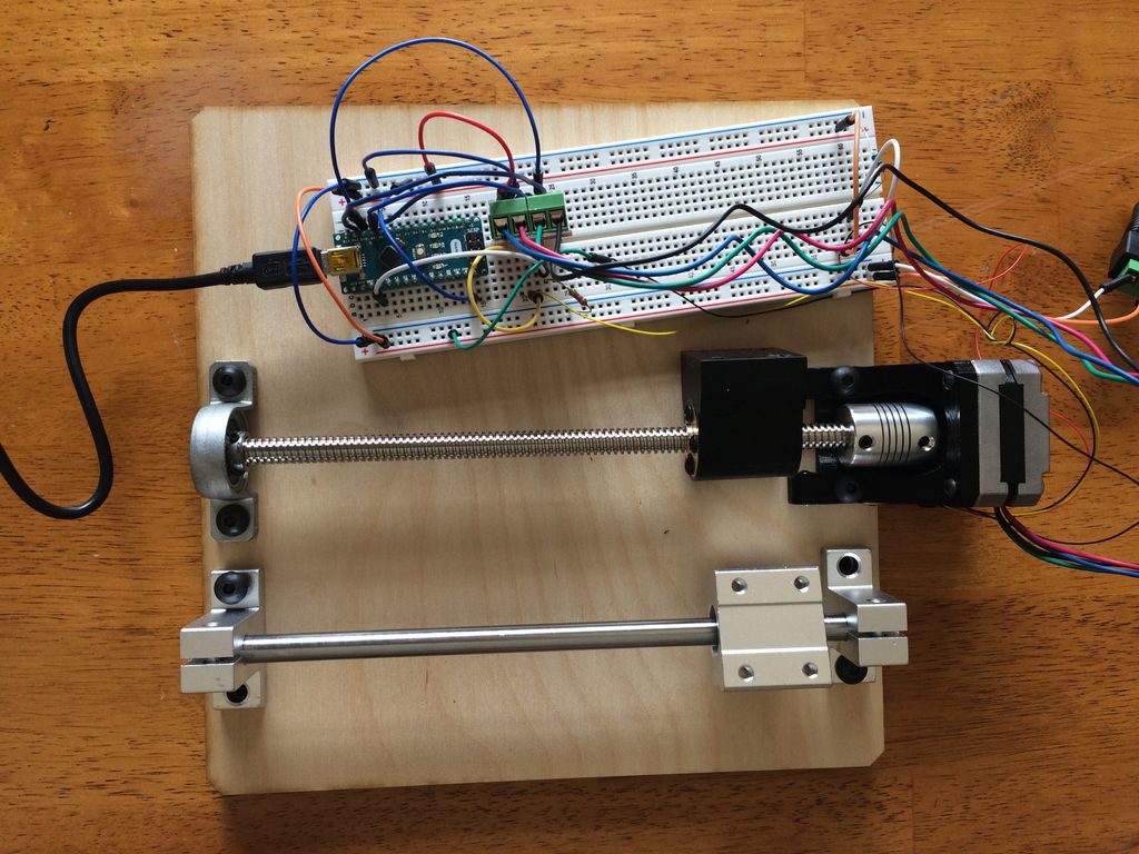
Being a camera operator is tough. Having to move the camera and maintain a smooth motion can be tricky, and the speed at which it’s done is never consistent. That’s what prompted Andy to create his own motorized robotic camera rig that can move in up to four different axes simultaneously. The camera gets attached to a standard mounting plate and then placed into the gimbal. The gimbal is able to both pitch the camera up (rotate around the X axis) and rotate it side to side (called ‘yaw’ or Z-axis rotation). In order to prevent a bunch of wires from tangling around each other while spinning, each rotational axis uses a slipring to transfer electrical power and signals continuously. 

Most of the magic is housed in the electronics and software. Andy went with an Arduino Uno running Grbl firmware to translate GCODE commands into concrete actions with the stepper motors. He used a set of opto-interrupting modules that detect when an object has passed between an emitter and detector to signal when the axis is homed. And finally, a Raspberry Pi runs his custom program that takes in keyframe data, parses it, and sends it to the Uno. 

As you can see from his excellent video, the camera rig is amazing at capturing smooth, continuous shots along multiple axes. You can view more about this project on its Hackaday write-up

The post This low-cost motion control rig helps capture high-quality shots appeared first on Arduino Blog.

While taking photos today is normally a digital affair, there is a wealth of visual information stored on film negatives. Digitization is possible, but it tends to be rather time-intensive, so photographer/hacker Seckin Sinan Isik decided to automate the process.

His setup uses a film carrier augmented with a stepper motor and belt drive to advance the 35mm film under a tripod-mounted digital camera. This is controlled by an Arduino Nano, with the camera’s view shown via a video capture device on a nearby computer.

In one mode, the user can adjust the film position semi-manually using pushbuttons, then scan the negative. The whole process can also be automated, with a Python computer vision routine.

More details on the project can ben found in Isik’s PetaPixel article here.

Astrophotography can be challenging, in a large part because your subject matter — or your base, the Earth rather — is constantly moving. In order to take excellent long exposures of far-off objects, Redditor intercipere came up with a beautiful 3D-printable, star-following mount that holds and rotates a DSLR camera.

Now intercipere can simply input the RA/DEC coordinates and the device will automatically move to a desired target in the sky.

Motion is handled by an Arduino Uno and two small stepper motors, with a 16×2 LCD shield user interface. The rig is capable of tracking for at least four minutes, producing this photo of the Andromeda galaxy with a cheapo lens from a heavy light polluted area.

Normally the 10-50 gigapixels of a DSLR are good enough for nearly any photo you can imagine, but if you need more—and don’t want to spend many thousands of dollars—then this clever setup by Jon Bumstead may be just the thing.

His contraption uses a Nikon D5000 camera situated above a small photographic subject, which progressively moves in front of the lens using an X/Y stage setup. Motion is handled by pair of stepper motors, under the control of an Arduino Nano and two L9110 driver boards. The Nano also commands the camera to snap a picture when the subject in position, producing an array of photos that can be stitched together to form an image with extreme detail.

In optical microscopes, there is a fundamental trade-off between field-of-view and resolution: the finer the detail, the smaller the region imaged by the microscope. One way to overcome this limitation is to translate the sample and acquire images over a larger field-of-view. The basic idea is to stitch together many high resolution images to form a large FOV. In these images, you get to see both the full sample, as well as fine detail in any portion of the sample. The result is an image consisting of about a billion pixels, much larger in comparison to the pictures taken by a DSLR or smartphone, which typically have around 10 to 50 million pixels.

In this Instructable, I will go over how to build a microscope capable of imaging a 90mm x 60mm field-of-view with pixels corresponding to 2 micrometer at the sample (although, I think the resolution is probably closer to 15 micrometer). The system uses camera lenses, but the same concept can be applied using microscope objectives to get even finer resolution.

Jan
31

[Jordan] managed to cobble together his own version of a low resolution digital camera using just a few components. The image generated is pretty low resolution and is only in grey scale, but it’s pretty impressive what can be done with some basic hardware.

The heart of the camera is the image sensor. Most consumer digital cameras have tons of tiny receptors all jammed into the sensor. This allows for a larger resolution image, capturing more detail in a smaller space. Unfortunately this also usually means a higher price tag. [Jordan’s] sensor includes just a single pixel. The sensor is really just an infrared photodiode inside of a tube. The diode is connected to an analog input pin on an Arduino. The sensor can be pointed at an object, and the Arduino can sense the brightness of that one point.

In order to compile an actual image, [Jordan] needs to obtain readings of multiple points. Most cameras do this using the large array of pixels. Since [Jordan’s] camera only has a single pixel, he has to move it around and take each reading one at a time. To accomplish this, the Arduino is hooked up to two servo motors. This allows the sensor to be aimed horizontally and vertically. The Arduino slowly scans the sensor in a grid, taking readings along the way. A Processing application then takes each reading and compiles the final image.

Since this camera compiles an image so slowly, it sometimes has a problem with varying brightness. [Jordan] noticed this issue when clouds would pass over while he was taking an image. To fix this problem, he added an ambient light sensor. The Arduino can detect the amount of overall ambient light and then adjust each reading to compensate. He says it’s not perfect but the results are still an improvement. Maybe next time he can try it in color.


Filed under: Arduino Hacks
Jan
27

[AlxDroidDev] built himself a nice remote control box for CHDK-enabled cameras. If you haven’t heard of CHDK, it’s a pretty cool software modification for some Canon cameras. CHDK adds many new features to inexpensive cameras. In this case, [AlxDroidDev] is using a feature that allows the camera shutter to be activated via USB. CHDK can be run from the SD card, so no permanent modifications need to be made to the camera.

[AlxDroidDev’s] device runs off of an ATMega328p with Arduino. It operates from a 9V battery. The circuit contains an infrared receiver and also a Bluetooth module. This allows [AlxDroidDev] to control his camera using either method. The device interfaces to the camera using a standard USB connector and cable. It contains three LEDs, red, green, and blue. Each one indicates the status of a different function.

The Arduino uses Ken Shirrif’s IR Remote library to handle the infrared remote control functions. SoftwareSerial is used to connect to the Bluetooth module. The Arduino code has built-in functionality for both Canon and Nikon infrared remote controls. To control the camera via Bluetooth, [AlxDroidDev] built a custom Android application. The app can not only control the camera’s shutter, but it can also control the level of zoom.


Filed under: Arduino Hacks
Dec
20

OV7670 Camera Module DIY Guide

arduino, camera, image, JPEG, OV7670, photo Comments Off on OV7670 Camera Module DIY Guide 

camera-0706-A

This camera module can perform image processing such as AWB (auto white balance), AE (automatic exposure) and AGC (automatic gain control), for the video signal coming from CMOS sensor. What’s more, in fusion of other advanced technology such as image enhancement processing under low illumination, and image noise intelligent forecast and suppress, this module would output high quality digital video signals by standard CCIR656 interface. OV7670 built-in JPEG decoder supported reatime encoding for collected image, and external controller can easily read the M – JPEG video streams, achieving the camera design of double stream. OV7670 supported motion detection and OSD display function of screen characters and pattern overlay, capable of self-defining detection area and sensitivity.

OV7670 Camera Module DIY Guide - [Link]

Oct
02

Simple Photo Flash Trigger for Water Balloon Photography

arduino, arduino hacks, balloons, flash, photo, Photography, trigger, water Comments Off on Simple Photo Flash Trigger for Water Balloon Photography 

Water Balloon Photography

There have been countless projects to make custom photo flash trigger circuits. Usually the circuits react to sound, triggering the camera flash at the moment a certain sound is triggered. That type of trigger can be used to detect the popping of a balloon or shattering of glass. Other triggers detect motion, like a projectile crossing a laser beam for example. [Udo's] friend had a fun idea to take photos of water balloons popping. Unfortunately neither of those trigger methods would be well suited for this situation. That’s when [Udo] had to get creative.

[Udo] built a unique trigger circuit that uses the water inside the balloon as the trigger. The core component of the circuit is an Arduino. One of the Arduino’s analog pins is configured to enable the internal pull-up resistor. If nothing else is connected to the pin, the Arduino will read 5 volts there. The pin is connected to a needle on the end of a stick. There is a second needle on the same stick, just a short distance away from the first. When these needles pierce the balloon’s skin, the water inside allows for a brief moment of conductivity between the two pins. The voltage on the analog pin then drops slightly, and the Arduino can detect that the balloon has popped.

[Udo] already had a flash controller circuit. He was able to trigger it with the Arduino by simply trying the flash controller’s trigger pin to one of the Arduino’s pins. If the Arduino pulls the pin to ground, it closes the switch on the flash controller and the flash is triggered. Both circuits must share a common ground in order for this to work.

All of the code for [Udo's] project is freely available. With such spectacular photographs, it’s only a matter of time before we see more of these floating around.


Filed under: Arduino Hacks

Strobe Remote

If you want to take a photograph with a professional look, proper lighting is going to be critical. [Richard] has been using a commercial lighting solution in his studio. His Lencarta UltraPro 300 studio strobes provide adequate lighting and also have the ability to have various settings adjusted remotely. A single remote can control different lights setting each to its own parameters. [Richard] likes to automate as much as possible in his studio, so he thought that maybe he would be able to reverse engineer the remote control so he can more easily control his lighting.

[Richard] started by opening up the remote and taking a look at the radio circuitry. He discovered the circuit uses a nRF24L01+ chip. He had previously picked up a couple of these on eBay, so his first thought was to just promiscuously snoop on the communications over the air. Unfortunately the chips can only listen in on up to six addresses at a time, and with a 40-bit address, this approach may have taken a while.

Not one to give up easily, [Richard] chose a new method of attack. First, he knew that the radio chip communicates to a master microcontroller via SPI. Second, he knew that the radio chip had no built-in memory. Therefore, the microcontroller must save the address in its own memory and then send it to the radio chip via the SPI bus. [Richard] figured if he could snoop on the SPI bus, he could find the address of the remote. With that information, he would be able to build another radio circuit to listen in over the air.

Using an Open Logic Sniffer, [Richard] was able to capture some of the SPI communications. Then, using the datasheet as a reference, he was able to isolate the communications that stored information int the radio chip’s address register. This same technique was used to decipher the radio channel. There was a bit more trial and error involved, as [Richard] later discovered that there were a few other important registers. He also discovered that the remote changed the address when actually transmitting data, so he had to update his receiver code to reflect this.

The receiver was built using another nRF24L01+ chip and an Arduino. Once the address and other registers were configured properly, [Richard's] custom radio was able to pick up the radio commands being sent from the lighting remote. All [Richard] had to do at this point was press each button and record the communications data which resulted. The Arduino code for the receiver is available on the project page.

[Richard] took it an extra step and wrote his own library to talk to the flashes. He has made his library available on github for anyone who is interested.


Filed under: Arduino Hacks, radio hacks


  • Newsletter

    Sign up for the PlanetArduino Newsletter, which delivers the most popular articles via e-mail to your inbox every week. Just fill in the information below and submit.

  • Like Us on Facebook