Posts | Comments

Planet Arduino

Archive for the ‘CMOS’ Category

Looks like another shot has been fired in the simmering Coil Gun Control War. This time, [Great Scott] is taken to the discrete woodshed with a simplified and improved control circuit using a single CMOS chip and a few transistors. Where will it end? Won’t somebody think of the children?

The latest salvo is in response to [GreatScott]’s attempt to control a DIY coil gun with discrete logic, which in turn was a response to comments that he took the easy way out and used an Arduino in the original build. [Great Scott]’s second build was intended to justify the original design choice, and seemed to do a good job of explaining how much easier and better the build was with a microcontroller. Case closed, right?

Nope. Embedded designer [fede.tft] wasn’t sure the design was even close to optimized, so he got to work — on his vacation, no less!’ He trimmed the component count down to a single CMOS chip (a quad Schmitt trigger NAND), a couple of switching transistors, the MOSFETs that drive the coils, and a few passives. The NANDs are set up as flip-flops that are triggered and reset by the projectile sensors, which are implemented as hardwired AND gates. The total component count is actually less than the support components on the original Arduino build, and [fede.tft] goes so far as to offer ideas for an alternative that does away with the switching transistors.

Even though [fede.tft] admits that [GreatScott] has him beat since he actually built both his circuits, hats off to him for showing us what can likely be accomplished with just a few components. We’d like to see someone implement this design, and see just how simple it can get.


Filed under: Arduino Hacks, weapons hacks
Nov
18

Kit Review – Altronics 3 Digit Counter Module

4029, 4511, altronics, CMOS, counter, digit, digital, Electronics, K2505, kit, kit review, LED, review, three, tronixstuff Comments Off on Kit Review – Altronics 3 Digit Counter Module 

Introduction

In this review we examine the three digit counter module kit from Altronics. The purpose of this kit is to allow you to … count things. You feed it a pulse, which it counts on the rising edge of the signal. You can have it count up or down, and each kit includes three digits.

You can add more digits, in groups of three with a maximum of thirty digits. Plus it’s based on simple digital electronics (no microcontrollers here) so there’s some learning afoot as well. Designed by Graham Cattley the kit was first described in the now-defunct (thanks Graham) January 1998 issue of Electronics Australia magazine.

Assembly

The kit arrives in the typical retail fashion:

Altronics K2505 Counter Module Kit

And includes the magazine article reprint along with Altronics’ “electronics reference sheet” which covers many useful topics such as resistor colour codes, various formulae, PCB track widths, pinouts and more. There is also a small addendum which uses two extra (and included) diodes for input protection on the clock signal:

Altronics K2505 Counter Module Kit instructions

The counter is ideally designed to be mounted inside an enclosure of your own choosing, so everything required to build a working counter is included however that’s it:

Altronics K2505 Counter Module Kit parts

No IC sockets, however I decided to live dangerously and not use them – the ICs are common and easily found. The PCBs have a good solder mask and silk screen:

Altronics K2505 Counter Module Kit PCBs

Altronics K2505 Counter Module Kit PCBs rear

With four PCBs (one each for a digit control and one for the displays) the best way to start was to get the common parts out of the way and fitted, such as the current-limiting resistors, links, ICs, capacitors and the display module. The supplied current-limiting resistors are for use with a 9V DC supply, however details for other values are provided in the instructions:

Altronics K2505 Counter Module Kit

Altronics K2505 Counter Module Kit

Altronics K2505 Counter Module Kit

At this point you put one of the control boards aside, and then start fitting the other two to the display board. This involves holding the two at ninety degrees then soldering the PCB pads to the SIL pins on the back of the display board. Starting with the control board for the hundreds digit first:

Altronics K2505 Counter Module Kit

Altronics K2505 Counter Module Kit

… at this stage you can power the board for a quick test:

Altronics K2505 Counter Module Kit

… then fit the other control board for the tens digit and repeat:

Altronics K2505 Counter Module Kit

Now it’s time to work with the third control board. This one looks after the one’s column and also a few features of the board. Several functions such as display blanking, latch (freeze the display while still counting) and gate (start or stop counting) can be controlled and require resistors fitted to this board which are detailed in the instructions.

Finally, several lengths of wire (included) are soldered to this board so that they can run through the other two to carry signals such as 5V, GND, latch, reset, gate and so on:

Altronics K2505 Counter Module Kit

These wires can then be pulled through and soldered to the matching pads once the last board has been soldered to the display board:

Altronics K2505 Counter Module Kit

 You also need to run separate wires between the carry-out and clock-in pins between the digit control boards (the curved ones between the PCBs):

Altronics K2505 Counter Module Kit

For real-life use you also need some robust connections for the power, clock, reset lines, etc., however for demonstration use I just used alligator clips. Once completed a quick power-up showed the LEDs all working:

Altronics K2505 Counter Module Kit

How it works

Each digit is driven by a common IC pairing – the  4029 (data sheet) is a presettable up/down counter with a BCD (binary-coded decimal) output which feeds a 4511 (data sheet) that converts the BCD signal into outputs for a 7-segment LED display. You can count at any readable speed, and I threw a 2 kHz square-wave at the counter and it didn’t miss a beat. By default the units count upwards, however by setting one pin on the board LOW you can count downwards.

Operation

Using the counters is a simple matter of connecting power, the signal to count and deciding upon display blanking and the direction of counting. Here’s a quick video of counting up, and here it is counting back down.

Conclusion

This is a neat kit that can be used to count pulses from almost anything. Although some care needs to be taken when soldering, this isn’t anything that cannot be overcome without a little patience and diligence. So if you need to count something, get one ore more of these kits from Altronics. Full-sized images are available on flickr. And while you’re here – are you interested in Arduino? Check out my new book “Arduino Workshop” from No Starch Press – also shortly available from Altronics.

In the meanwhile have fun and keep checking into tronixstuff.com. Why not follow things on twitterGoogle+, subscribe  for email updates or RSS using the links on the right-hand column? And join our friendly Google Group – dedicated to the projects and related items on this website. Sign up – it’s free, helpful to each other –  and we can all learn something.

The post Kit Review – Altronics 3 Digit Counter Module appeared first on tronixstuff.

Hello readers

Today we conclude the series of articles on the resistor. You may also enjoy part one and two.

With regards to this article, it is only concerned with direct current (DC) circuits.

Pull up and pull down resistors

When working with digital electronics circuits, you will most likely be working with CMOS integrated circuits, such as the 4541 programmable timer we reviewed in the past. These sorts of ICs may have one or more inputs, that can read a high state (like a switch being on) or a low state (or like a switch being off). In fact you would use a switch in some cases to control these inputs. Consider the following hypothetical situation with a hypothetical CMOS IC in part of a circuit from a hypothetical designer:


The IC in this example has two inputs, A and B. The IC sets D high if input A is high (5V), and low if A is low (0V). The designer has placed a button (SW1) to act as the control of input A. Also, the IC sets C high if input B is low (0V) or low if it is high (5V). So again, the designer has placed another button (SW2) to act as the control of input B, when SW2 is pressed, B will be low.

However when the designer breadboarded the circuit, the IC was behaving strangely. When they pressed a button, the correct outputs were set, but when they didn’t press the buttons, the IC didn’t behave at all. What was going on? After a cup of tea and a think, the designer realised – “Ah, for input A, high is 5V via the button, but what voltage does the IC receive when A is low? … and vice-versa for input B”. As the inputs were not connected to anything when the buttons were open, they were susceptible to all sorts of interference, with random results.

So our designer found the data sheet for the IC, and looked up the specification for low and high voltages:

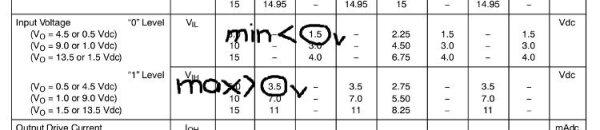
“Aha … with a supply voltage of 5V, a low input cannot be greater than 1.5V, and a high input must be greater than 3.5V. I can fix that easily!”. Here was the designer’s fix:

On paper, it looked good. Input A would be perfectly low (0V) when the SW1 was not being pressed, and input B would be perfectly high (connected to 5V) when SW2 was not pressed. The designer was in a hurry, so they breadboarded the circuit and tested the resulting C and D outputs when SW1 and SW2 were pressed. Luckily, only for about 30 seconds, until their supervisor walked by and pointed out something very simple, yet very critical: when either button was pressed in, there would be a direct short from supply to ground! Crikey… that could have been a bother. The supervisor held their position for a reason, and made the following changes to our designer’s circuit:

Instead of shorting the inputs straight to supply or earth, they placed the resistors R1 and R2 into the circuit, both 10k ohm value. Why? Looking at SW1 and input A, when SW1 is open, input A is connected to ground via the 10k resistor R1. This will definitely set input A to zero volts when SW1 is open – perfect. However when SW1 is closed, input A is connected directly to 5V (great!) making it high. Some current will also flow through the resistor, which dissipates it as heat, and therefore not shorting out the circuit (even better). You can use Ohm’s law to calculate the current through the resistor:

I (current) = 5 (volts) / 10000 (ohms) = 0.0005 A, or half a milliamp.

As power dissipated (watts) = voltage x current, power equals 0.0025 watts, easily handled by a common 1/4 watt resistor. Our resistor R1 is called a pull-down resistor as it pulls the voltage at input A down to zero volts.

And with R2, when SW2 is open, input B is connected directly to 5V via R2. However. as the IC inputs are high impedance, the voltage at input B will still be 5V (perfect). When SW2 is closed, input B will be set to zero volts, via the direct connection to ground. Again, some current will flow through the resistor R2, in the same way as R1. However, in this situation, we call R2 a pull-up resistor, as it pulls the voltage at input B up to 5V.

Generally 10k ohm resistors are the norm with CMOS digital circuits like the ones above, so you should always have a good stock of them.

If you are using TTL ICs, inputs should still not be left floating, use a pull-up resistor of 10k ohm as well.

Pull-up resistors can also be used in other situations, such as maintaining voltages on data bus lines, such as the I2C bus (as used in our Arduino clock tutorials).

So that is the resistor. I hope you understood and can apply what we have discussed. If you feel something is missing, or would like further explanations, please ask.

As always, thank you for reading and I look forward to your comments and so on. Furthermore, don’t be shy in pointing out errors or places that could use improvement. Please subscribe using one of the methods at the top-right of this web page to receive updates on new posts. Or join our new Google Group.

Otherwise, have fun, be good to each other – and make something! :)

Thank you!


  • Newsletter

    Sign up for the PlanetArduino Newsletter, which delivers the most popular articles via e-mail to your inbox every week. Just fill in the information below and submit.

  • Like Us on Facebook