Posts | Comments

Planet Arduino

Archive for the ‘photodiode’ Category

[jbumstead] used MATLAB to convert the text messages into binary to be cut out of the disk.
[jbumstead] wanted to demonstrate the idea of information-storing devices such as LPs, CDs, and old hard drives. What he came up with lies directly at the intersection of art and technology: an intricately-built machine that plays beautiful collaged wooden disks. Much like the media that inspired the Wooden Disk Player, it uses a laser to read encoded data, which in this case is short bits of text like “Don’t Panic”.

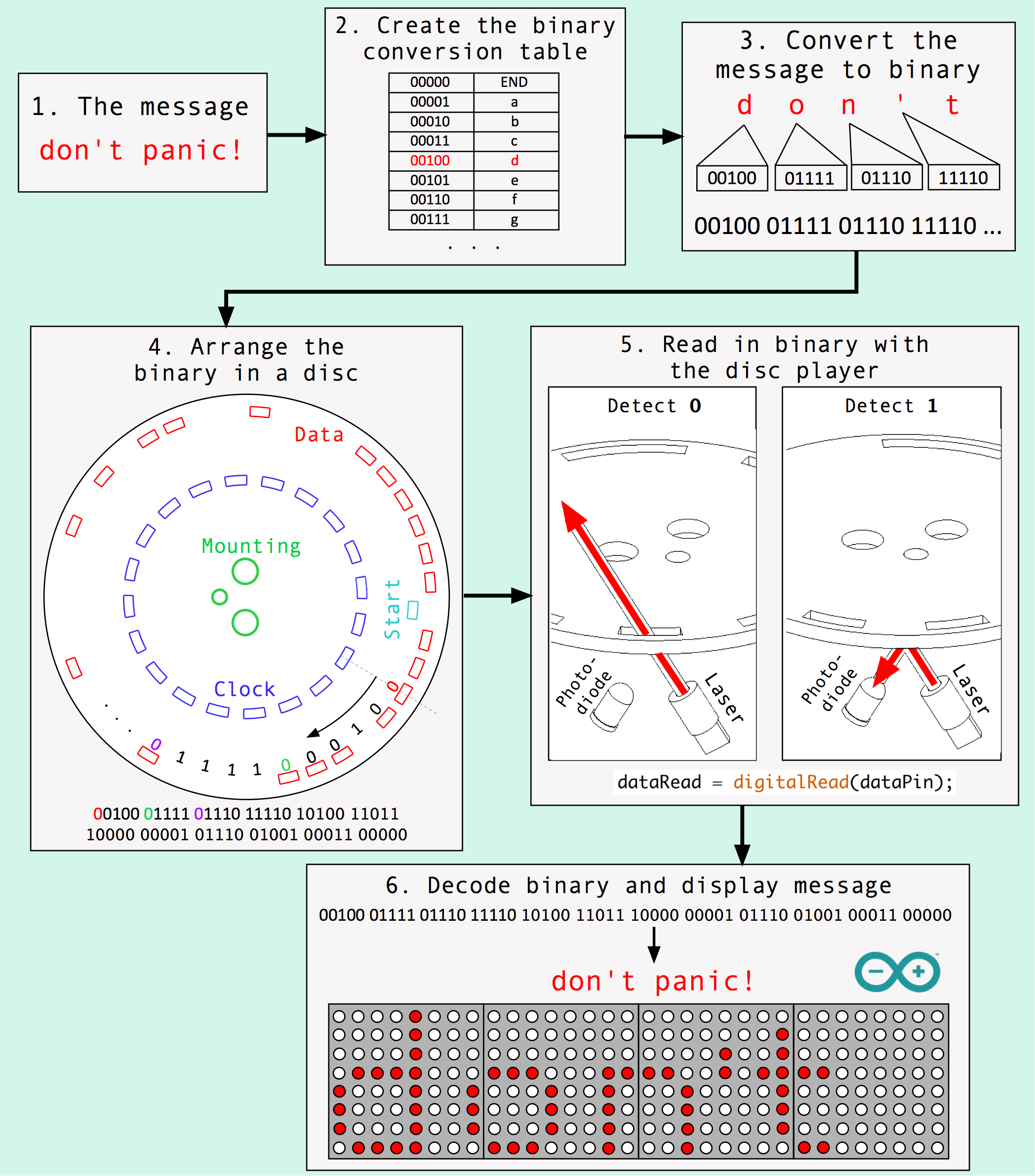
These snippets are stored in binary and read by a laser and photodiode pair that looks for holes and not-holes in the disk. The message is then sent to an Arduino Nano, which translates it into English and scrolls the text on an LED matrix. For extra fun, the Nano plays a MIDI note every time it reads a 1, and you can see the laser reading the disk through a protective acrylic shield.

Though the end result is fantastic, [jbumstead] had plenty of issues along the way which are explored in the build video after the break. We love it when people show us their mistakes, because it happens to all of us and we shouldn’t ever let it tell us to stop hacking.

If anyone knows their way around lasers, it’s [jbumstead]. We loved playing their laser harp at Supercon!

Via adafruit

When [millerman4487] bought a TCS230-based color sensor, he was expecting a bit more documentation. Since he didn’t get it, he did a little research and some experimentation and wrote it up to help the rest of us.

The TCS3200 uses an 8×8 array of photodiodes. The 64 diodes come in four groups of 16. One group has a blue filter, one has green and the other has a red filter. The final set of diodes has no filter at all. You can select which group of diodes is active at any given time.

Sixteen photodiodes have blue filters, 16 photodiodes have green filters, 16 photodiodes have red filters, and 16 photodiodes are clear with no filters. The four types (colors) of photodiodes are interdigitated to minimize the effect of non-uniformity of incident irradiance. All photodiodes of the same color are connected in parallel. Pins S2 and S3 are used to select which group of photodiodes (red, green, blue, clear) are active.

The output of the array is a frequency that corresponds to the light intensity measured by one bank of photodiodes. You’ll need to make several pulse input measurements to compute the color and [millernam4487] provides code for it. You may, however, need to calibrate the device before you get good results.

We’ve looked at color sensors before, of course. They can even unlock doors.

Chances are pretty good you’ve had a glowing probe clipped to your fingertip or earlobe in some clinic or doctor’s office. If you have, then you’re familiar with pulse oximetry, a cheap and non-invasive test that’s intended to measure how much oxygen your blood is carrying, with the bonus of an accurate count of your pulse rate. You can run down to the local drug store or big box and get a fingertip pulse oximeter for about $25USD, but if you want to learn more about photoplethysmography (PPG), [Rajendra Bhatt]’s open-source pulse oximeter might be a better choice.

PPG is based on the fact that oxygenated and deoxygenated hemoglobin have different optical characteristics. A simple probe with an LED floods your fingertip with IR light, and a photodiode reads the amount of light reflected by the hemoglobin. [Rajendra]’s Easy Pulse Plugin receives and amplifies the signal from the probe and sends it to a header, suitable for Arduino consumption. What you do with the signal from there is up to you – light an LED in time with your heartbeat, plot oxygen saturation as a function of time, or drive a display to show the current pulse and saturation.

We’ve seen some pretty slick DIY pulse oximeters before, and some with a decidedly home-brew feel, but this seems like a good balance between sophisticated design and open source hackability. And don’t forget that IR LEDs can be used for other non-invasive diagnostics too.

The 2015 Hackaday Prize is sponsored by:


Filed under: Arduino Hacks, Medical hacks, The Hackaday Prize
Jan
31

[Jordan] managed to cobble together his own version of a low resolution digital camera using just a few components. The image generated is pretty low resolution and is only in grey scale, but it’s pretty impressive what can be done with some basic hardware.

The heart of the camera is the image sensor. Most consumer digital cameras have tons of tiny receptors all jammed into the sensor. This allows for a larger resolution image, capturing more detail in a smaller space. Unfortunately this also usually means a higher price tag. [Jordan’s] sensor includes just a single pixel. The sensor is really just an infrared photodiode inside of a tube. The diode is connected to an analog input pin on an Arduino. The sensor can be pointed at an object, and the Arduino can sense the brightness of that one point.

In order to compile an actual image, [Jordan] needs to obtain readings of multiple points. Most cameras do this using the large array of pixels. Since [Jordan’s] camera only has a single pixel, he has to move it around and take each reading one at a time. To accomplish this, the Arduino is hooked up to two servo motors. This allows the sensor to be aimed horizontally and vertically. The Arduino slowly scans the sensor in a grid, taking readings along the way. A Processing application then takes each reading and compiles the final image.

Since this camera compiles an image so slowly, it sometimes has a problem with varying brightness. [Jordan] noticed this issue when clouds would pass over while he was taking an image. To fix this problem, he added an ambient light sensor. The Arduino can detect the amount of overall ambient light and then adjust each reading to compensate. He says it’s not perfect but the results are still an improvement. Maybe next time he can try it in color.


Filed under: Arduino Hacks
Jan
11

There are many ways to detect a heartbeat electronically. One of the simpler ways is to take [Orlando’s] approach. He’s built a finger-mounted pulse detector using a few simple components and an Arduino.

This circuit uses a method known as photoplethysmography. As blood is pumped through your body, the volume of blood in your extremities increases and decreases with each heartbeat. This method uses a light source and a detector to determine changes in the amount of blood in your extremities. In this case, [Orlando] is using the finger.

[Orlando] built a finger cuff containing an infrared LED and a photodiode. These components reside on opposite sides of the finger. The IR LED shines light through the finger while the photodiode detects it on the other side. The photodiode detects changes in the amount of light as blood pumps in and out of the finger.

The sensor is hooked up to an op amp circuit in order to convert the varying current into a varying voltage. The signal is then filtered and amplified. An Arduino detects the voltage changes and transmits the information to a computer via serial. [Orlando] has written both a LabVIEW program as well as a Processing program to plot the data as a waveform. If you’d rather ditch the PC altogether, you might want to check out this standalone heartbeat sensor instead.


Filed under: Arduino Hacks


  • Newsletter

    Sign up for the PlanetArduino Newsletter, which delivers the most popular articles via e-mail to your inbox every week. Just fill in the information below and submit.

  • Like Us on Facebook