Posts | Comments

Planet Arduino

Archive for the ‘CRO’ Category

Hello readers

Today we are going to examine the Texas Instruments TLC5940 16-channel LED driver IC. My reason for doing this is to demonstrate another, easier way of driving many LEDs as well as LED display modules that are common-anode. If you have a common-cathode display module, you should have a look at the Maxim MAX7219. Moving along, here is the IC:

Another nice big DIP IC. Also available in HTSSOP and QFN packaging. What can this IC do for us? It can control 16 LEDs per IC, and also be cascaded to control more and more, with the display data arriving via a serial line in the same manner as a 74HC595 shift register. Furthermore, another benefit of this IC is that you don’t need matching current-limiting resistors for your LEDs, as this IC is a current sink, in that the current flows from the 5V rail, through the LED, then into the IC. However, it can control the brightness of the LEDs using pulse-width modulation over 4096 steps via software, or using a single resistor.

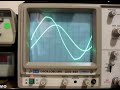
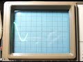
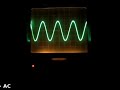
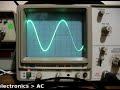
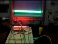
What is pulse-width modulation? Normally an LED might be on, or off. But if you switch it on and off very quickly, it does not look as bright (as it is not on 100% of the time). If you alter the period of time between on and off, you can alter the perceived brightness of the LED. Here is an example, compare the brightness of the LED bars against the display of the CRO – as the brightness increases, the voltage (amplitude [vertical thickness]) spreads across the entire time period (horizontal axis); as the brightness decreases, the voltage spread across time retreats:

Using the IC is very easy on the hardware front. Here is the data sheet: TLC5940.pdf. The pinout diagram is quite self-explanatory:

Pins OUT0~OUT15 are the current-sink pins for each LED. When one is selected they allow current to flow into the IC from the 5V rail, with the LED in between – turning it on. However it is easier to understand with a practical example, such as this (click to enlarge):

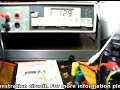
Here we have our Arduino board or compatible sending serial data to the TLC5940 to control sixteen LEDs. The 2k ohm resistor is required to set the maximum current available to flow through the LEDs, thereby adjusting their brightness. Using software you can adjust the brightness with PWM for each LED by itself. Very important: this circuit will need external power into the Arduino or a separate 5V power supply. The circuitry on the breadboard draws up to ~318 mA by itself – running the Arduino from USB only made it somewhat flaky in operation. Here is the circuit in action with an ammeter between the breadboard and 5V out on the Arduino:

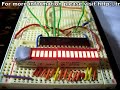
Anyhow, let’s get moving once more – here is the assembled demonstration circuit:

For our example, we will be using the Arduino way of doing things. Thankfully (once more) there is a library to make controlling the IC exponentially easier. The library page and download files are available from here; the documentation page is here.  If you need guidance on installing a library, please visit here. However the commands to control the IC are quite simple with the Arduino library.

First of all, include the TLC5940 library, as such:

#include “Tlc5940.h”

Then in void setup(); you create the object using the function:

Tlc.init();

You can insert a number between 0 and 4095 to set the starting PWM (LED brightness) value, however this is optional.

Setting an output for display requires two functions, first Tlc.set(l, p); where l is the output (0~15) and p is the PWM brightness level – then execute Tlc.update(); which sends the command to the IC to be executed. The sketch below is easy to follow and understand the process involved.

Moving forward with the demonstration, here is the sketch  – TLC5940demo.pdf, and the video clip of operation:

When the LEDs are glowing from dim to bright and return, we are altering the PWM value of the LEDs to adjust their brightness. This also occurs during the last operation where the LEDs are operating like the bonnet of KITT.

Well once again that’s enough blinkiness for now, again this is another useful IC that helps simplify things and be creative. As always, avoid the risk of counterfeit ICs  – so please avoid disappointment, support your local teams and buy from a reputable distributor. Living in Australia, mine came from Farnell (part number 1226306). So have fun!

Remember, if you have any questions at all please leave a comment (below). We also have a Google Group dedicated to the projects and related items on the website – please sign up, it’s free and we can all learn something. High resolution photos are available from flickr.

Otherwise, have fun, stay safe, be good to each other – and make something! :)

[Note – the TLC5940 was purchased by myself personally and reviewed without notifying the manufacturer or retailer]

Hello everyone

Today we are going to continue exploring alternating current, with regards to how resistors and capacitors deal with AC. This chapter is part two, chapter one is here.

To help with the explanations, remember this diagram:

That is, note that there are three possible voltage values, Vpp, Vp and Vrms. Moving on. Alternating current flows through various components just like direct current. Let’s examine some components and see.

First, the resistor. It operates in the same way with AC as it does DC, and the usual calculations apply with regards to Ohm’s law, dividing voltage and so on. However you must keep in mind the type of voltage value. For example, 10Vrms + 20Vpp does NOT equal 30 of anything. But we can work it out. 20Vpp is 10Vp,  which is 7.07Vrms… plus 10Vrms = 17.07Vrms. Therefore, 10Vrms + 20Vpp = 17.07Vrms.

Furthermore, when using Ohm’s law, or calculating power, the result of your equation must always reflect the type of voltage used in the calculations. For example:


Next, the capacitor. Capacitors oppose the flow of alternating current in an interesting way – in simple terms, the greater the frequency of the current, the less opposition to the current. However, we call this opposition reactance, which is measured in ohms. Here is the formula to calculate reactance:


the result Xc is measured in Ohms, f is frequency is Hertz, and C is capacitance in Farads. Here are two examples – note to convert the value of the capacitor back to Farads


Also consider if you have identical frequencies, a smaller capacitor will offer a higher resistance than a larger capacitor. Why is this so? A smaller capacitor will reach the peak voltages quicker as it charges in less time (as it has less capacitance); wheras a larger capacitor will take longer to charge and reach the peak voltage, therefore slowing down the current flow which in turn offers a higher reactance.

Resistors and capacitors can also work together as an AC voltage divider. Consider the following schematic:

As opposed to a DC voltage divider, R2 has been replaced with C1, the 0.1 uF capacitor. In order to calculate Vout, we will need the reactance of C1 – and subsitute that value for R2:

However, once the voltage has been divided, Vout has been transformed slightly – it is now out of phase. This means that Vout oscillates at the same frequency, but at different time intervals than Vin. The easiest way to visualise this is with an oscilloscope, which you can view below:

Please note that my CRO is not in the best condition. In the clip it was set to a time base of 2 milliseconds/division horizontal and 5 volts/division vertical.

Thus ends chapter two of our introduction to alternating current. I hope you understood and can apply what we have discussed today. As always, thank you for reading and I look forward to your comments and so on. Furthermore, don’t be shy in pointing out errors or places that could use improvement, you can either leave a comment below or email me – john at tronixstuff dot com.

Please subscribe using one of the methods at the top-right of this web page to receive updates on new posts. Or join our Google Group and post your questions there.

Otherwise, have fun, be good to each other – and make something! :)

Hello everyone!

Today we are going to introduce the basics of AC – alternating current. This is necessary in order to understand future articles, and also to explain in layperson’s terms what AC is all about. So let’s go!

AC – Alternating Current. We see those two letters all around us. But what is alternating current? How does current alternate? We know that DC (direct current) is the result of a chemical reaction of some sort – for example in a battery, or from a solar cell. We know that it can travel in either direction, and we have made use of it in our experimenting. DC voltage does not alter (unless we want it to).

Therein lies the basic difference – and why alternating current is what is is – it alternates! :) This is due to the way AC current is created, usually by a generator of some sort. In simple terms a generator can be thought of as containing a rotating coil of wire between two magnets. When a coil passes a magnet, a current is induced by the magnetic field. So when the coil rotates, a current is induced, and the resulting voltage is relative to the coil’s positioning with the magnets.

For example, consider the diagram below (exploded view, it is normally more compact):

This is a very basic generator. A rotating coil of wire is between two magnets. The spacing of the magnets in real life is much closer. So as the coil rotates, the magnetic fields induce a current through the coil, which is our alternating current. But as the coil rotates around and around, the level of voltage is relative to the distance between the coil and the magnet. The voltage increases from zero, then decreases, then increases… as the coil constantly rotates. If you were to graph the voltage level (y-axis) against time (x-axis), it would look something like below:

That graph is a sine wave… and is a representation of perfect AC current. If you were to graph DC voltage against time, it would be a straight horizontal line. For example, compare the two images below, 2 volts DC and AC, shown on an oscilloscope:

2 volts DC

The following clip is 2 volts AC, as shown on the oscilloscope:

So as you can see, AC is not a negative and positive current like DC, it swings between negative and positive very quickly. So how do you take the voltage measurement? Consider the following:

The zero-axis is the point of reference with regards to voltage. That is, it is the point of zero volts. In the oscilloscope video above, the maximum and minimum was 2 volts. Therefore we would say it was 2 volts peak, or 2Vp. It could also be referred to as 4 volts peak to peak, or 4Vpp – as there is a four volt spread between the maximum and minimum values of the sine wave. There is another measurement in the diagram above – Vrms, or volts root mean squared. The Vrms value is the amount of AC that can do the same amount of work as the equivalent DC voltage. Vrms = 0.707 x Vp; and Vp = 1.41 * Vrms. Voltages of power outlets are rated at Vrms instead of peak as this is relative to calculations. For example, in Australia we have 240 volts:

DO NOT do this

Well, close enough. In fact, our electricity distributor says we can have a tolerance of +/- 10%… some rural households can have around 260 volts. Moving on…

The final parameter of AC is the frequency, or how many times per second the voltage changes from zero to each peak then back to zero. That is the time for one complete cycle. The number of times this happens per second is the frequency, and is measured in Hertz (Hz). The most common frequency you will hear about is your domestic supply frequency. Australia is 50 Hz, the US is 60 Hz, etc. In areas that have a frequency of 60 Hz, accurate mains-powered time pieces can be used, as the seconds hand or counter can be driven from the frequency of the AC current.

The higher the frequency, the shorter the period of time taken by one cycle. The frequency and time are inversely proportional, so frequency = 1/time; and time – 1/frequency. For example, if your domestic supply is 50 Hz, the time for each cycle is 1/50 = 0.02 seconds. This change can be demonstrated quite well on an oscilloscope, for example:

In the video above there is 2 volts AC, and the frequency starts from 100 Hz, then moves around the range of 10 to 200 Hz. As you can see, the amplitude of the sine wave does not change (the height, which indicates the voltage) but the time period does alter, indicating the frequency is changing. And here is the opposite:

This video is a demonstration of changing the voltage, whilst maintaining a fixed frequency.

Thus ends the introduction to alternating current. In the next instalment about AC we will look at how AC works in electronic circuits, and how it is handled by various components.

I hope you understood and can apply what we have discussed today. As always, thank you for reading and I look forward to your comments and so on. Furthermore, don’t be shy in pointing out errors or places that could use improvement.

Please subscribe using one of the methods at the top-right of this web page to receive updates on new posts. Or join our Google Group and post your questions there.

Otherwise, have fun, be good to each other – and make something! :)


  • Newsletter

    Sign up for the PlanetArduino Newsletter, which delivers the most popular articles via e-mail to your inbox every week. Just fill in the information below and submit.

  • Like Us on Facebook