06
Kit Review – JYE Tech FG085 DDS Function Generator
dds, digital, direct, ds2102, fg085, frequency, function generator, generator, jyetech, kit, kit review, KIT-11394, learning electronics, review, rigol, servo, sine, square, staircase, sweep, synthesis, test equipment, triangle, tronixstuff, wave Comments Off on Kit Review – JYE Tech FG085 DDS Function Generator
Introduction
There has been a lot of talk lately about inexpensive DDS (direct digital synthesis) function generators, and I always enjoy a kit – so it was time to check out the subject of this review. It’s the “FG085 miniDDS function generator” from JYE Tech. JYE is a small company in China that makes inexpensive test equipment kits, for example their capacitance meter (my first kit review!) and DSO. The capacitance meter was good, the DSO not so good – so let’s hope this is better than their last efforts.
Assembly
The instructions (AssemblyGuide_085G) are much better than previous efforts, and if you have bought the kit – read them. The kit arrives in a large zip-lock bag, with the following bundle of parts:

The AC adaptor is 100~240V in, 15V DC out. Everything is included with the kit including a short BNC to alligator clips lead for output. The PCBs are very good, with a nice solder mask and silk screen:

and back:

At this point we realise that most of the work is already done. There’s two microcontrollers ATmega48 and ATmega168- one for display and user-interface control, and the other for function generation. It takes only a few minutes to solder in the through-hole parts, headers and sockets:

… then you flip over the PCB and add the LCD:

… followed by the buttons and rotary encoder. From previous research this is the part that causes people a lot of trouble – so read carefully. There’s a lot of buttons – and if they aren’t inserted into the PCB correctly your life will become very difficult. The buttons must be inserted a certain way – they’re “polarised” – for example:

As you can see above, one side has a double-vertical line and the other side has a single. When you fit the buttons to the PCB – the side with the double-vertical must face the left-hand side of the PCB – the side with the DC socket. For example:

Furthermore, don’t be in a rush and put all the buttons in then try to solder them all at once. Do them one at a time, and hold them tight to the PCB with some blu-tac or similar. If they don’t sit flush with the PCB the front panel won’t fit properly and the buttons will stick when in use. So exercise some patience, and you’ll be rewarded with an easy to use function generator. Rush them in and you’ll be very unhappy. I warned you! After fitting each button, test fit the front panel to check the alignment, for example:

Then you end up with nicely-aligned buttons:

… which all operate smoothly when the panel is fitted:

After the buttons comes the rotary encoder. Be very careful when fitting it to the PCB – the data legs are really weak, and bend without much effort. If you push in the encoder, be mindful of the legs not going through the holes and bending upwards. Furthermore, when soldering in the encoder note that you’re really close to an electrolytic – you don’t want to stab it with a hot iron:

The CP2012 chip in the image above is for the USB interface. More on that later. Now the next stage is the power-test. Connect DC power and turn it on – you should be greeted by a short copyright message followed by the operation display:

If you didn’t – remove the power and check your soldering – including the capacitor polarities and look for bridges, especially around the USB socket. Now it’s time to fit the output BNC socket. For some reason only known to the designers, they have this poking out the front of the panel for the kit – however previous revisions have used a simple side-entry socket. Thus you need to do some modifications to the supplied socket. First, chop the tag from the sprocket washer:

… then remove the paper from the front panel:

Now solder a link to the washer in a vertical position:

… then fit the BNC socket to the panel, with the washer aligned as such:

Finally, align the top panel with the PCB so the BNC socket pin and washer link drop into the PCB and solder them in:

If you want to use the servo mode, solder three short wires that can attach to a servo form the three “output” pads between the BNC and USB socket.
Finally, screw in the panels and you’re finished!

Using the function generator
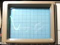
Operation is quite simple, and your first reference should be the manual (manual.pdf). The display defaults to normal function generator mode at power-up – where you can adjust the frequency, offset, amplitude and type of output – sine, square, triangle, ramp up, ramp down, staircase up and down:

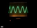
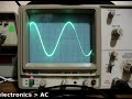
The ranges for all functions is 0~10 khz, except for sine which can hit 200 kHz. You can enter higher frequencies, such as up to 250 kHz for sine – but the results aren’t so good.
Instead of filling this review with lots of screen dumps from an oscilloscope to demonstrate the output – I’ve made the following video where you can see various functions being displayed on a DSO:
You can also create signals to test servos, with adjustable pulse-width, amplitude and cycle times. However you’ll need to solder three wires onto the PCB (next to the BNC socket area) to attach to the servo.
According to the user manual and various retailers’ websites – the FG085 can generate frequency sweeping signals. These are signals that sweep from a start to as finish frequency over a period of time. However the firmware on the supplied unit is old and needs updating to enable this function. You can download the firmware in .hex file format from here. Then go and dig up an AVR programmer and avrdude. At the time of writing we had some issues with the signature not being recognised when updating the firmware, and solidly bricked the FG085. Our fault – so when that’s sorted out we’ll update the review – stay tuned.
There is also a USB port on the side – after installing CP2102 drivers in Windows we could connect at 115200 bps with terminal, however all the FG085 returned was the firmware version number. Perhaps later on the designers will update the firmware to allow for PC control. Somehow I wouldn’t bank on it.
Oh – if you’re wondering what DDS is - click here!
Conclusion
It’s an interesting piece of equipment. Putting the firmware upgrade issues to one side, the FG085 does what it sets out to do. During testing it worked well, and we didn’t come across any obvious inaccuracies during use. The price varies between US$43 and $50 – so for that money it’s a good kit. Just take care during construction and you’ll be fine.
The function generator is available in kit form or assembled, with or without panels from China. The kit version with panels is also available from Sparkfun (KIT-11394) and their resellers. Full-sized images available on flickr. This kit was purchased and reviewed without notifying the supplier.

In the meanwhile have fun and keep checking into tronixstuff.com. Why not follow things on twitter, Google+, subscribe for email updates or RSS using the links on the right-hand column? And join our friendly Google Group – dedicated to the projects and related items on this website. Sign up – it’s free, helpful to each other – and we can all learn something.