Posts | Comments

Planet Arduino

Archive for the ‘robot arm’ Category

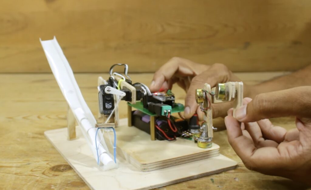
We all know how annoying a ceiling fan can be when it isn’t balanced well and that annoyance perfectly demonstrates the necessity of a good, sturdy bearing. A ceiling fan’s bearing needs to allow for smooth rotational motion with as little friction as possible, while completely constraining movement in every other axis. Those properties make a ceiling base a surprisingly good starting point for a SCARA, as demonstrated in tuenhidiy’s recent Instructables write-up.

In their tutorial, tuenhidiy refers to this as a “Spaceship Scara Arm.” It isn’t exactly clear why they chose the “spaceship” terminology, but it is similar to a conventional SCARA (Selective Compliance Assembly Robot Arm) — just one with only two degrees of freedom (DOF).

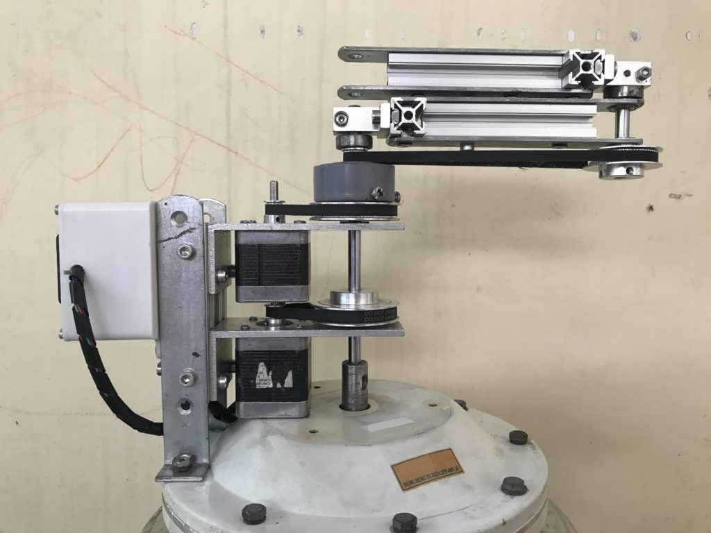
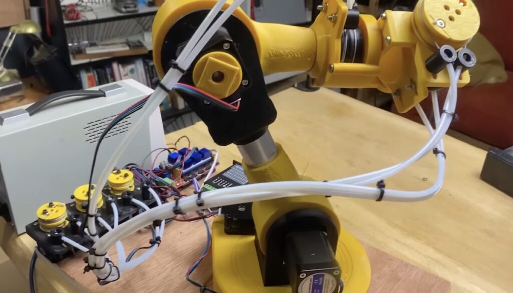
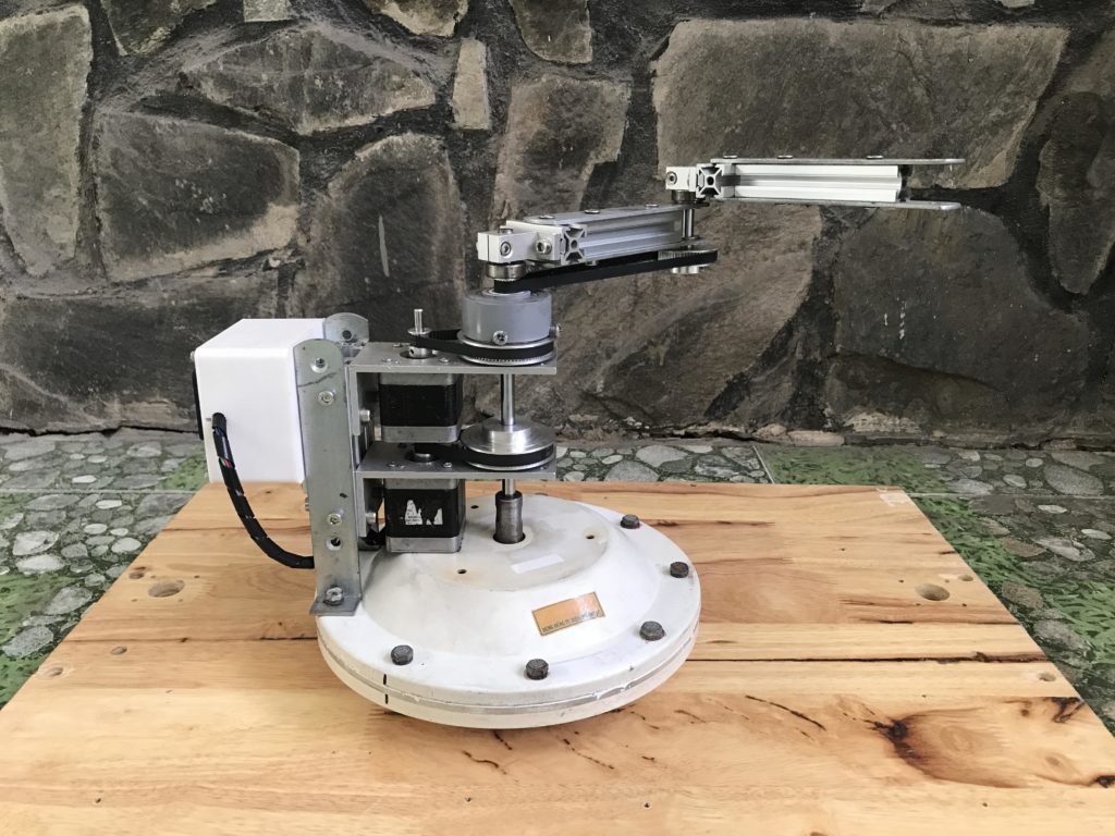
The entire point of a SCARA is that it is fully constrained, except for rotation around the Z axis at each joint. After their ceiling fan broke, tuenhidiy noticed that the fan’s base with its beefy bearing would be perfect for this application. They took that, added a couple of stepper motors and belts, some aluminum extrusion, and a couple more bearings to create this simple SCARA.

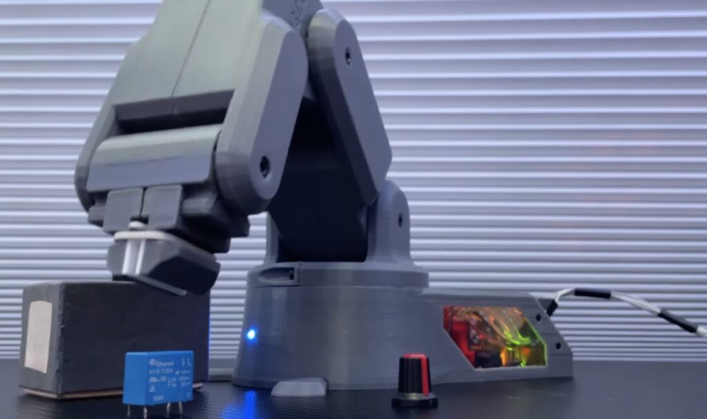
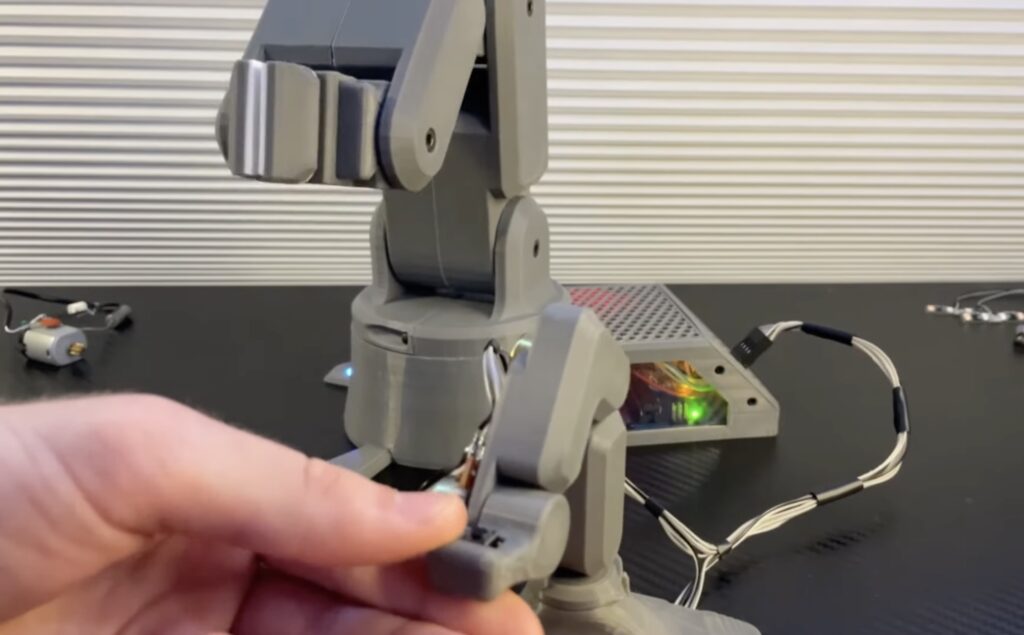
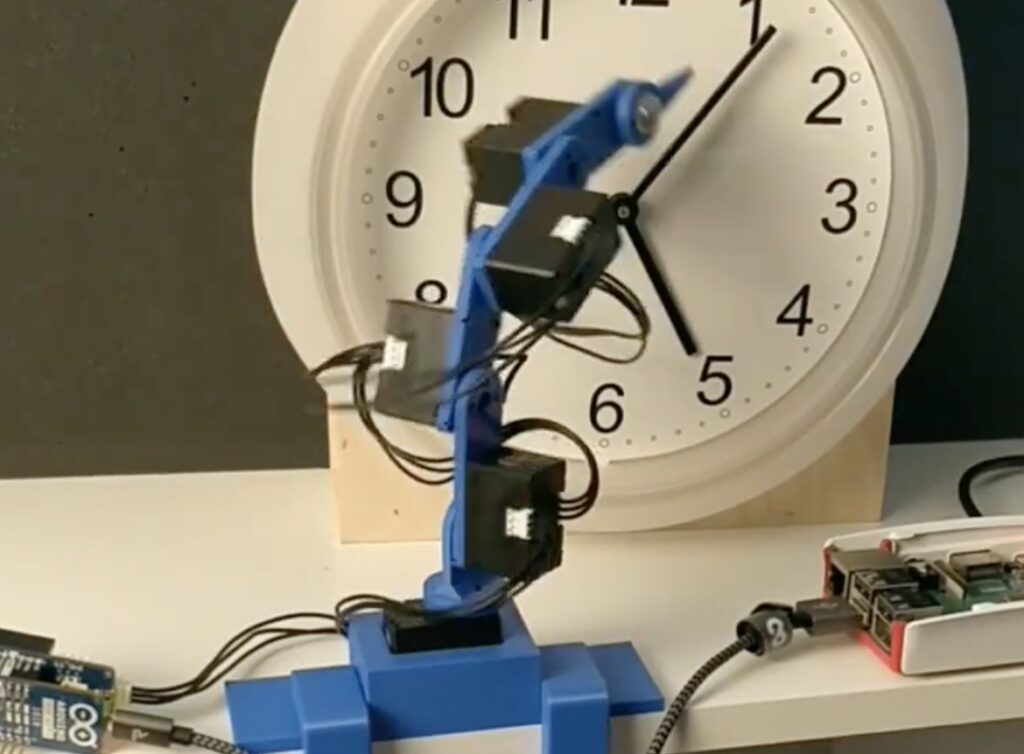
An Arduino UNO Rev3 board controls those motors through a CNC Shield V3. Grbl firmware makes it easy to control the positions of the motors using just about any software a user could possibly want. Some simple calculations regarding the arm’s geometry and gear ratios should let appropriate software determine exactly where it is in space. For a demonstration, tuenhidiy added a DC solenoid for its magnetic capabilities. But anyone replicating this project can add their own end effector to suit their needs.

The post Ceiling fan becomes a “spaceship” SCARA robot arm appeared first on Arduino Blog.

There are many ways to control a robot arm, with the simplest being a sequential list of rotation commands for the motors. But that method is very inefficient when the robot needs to do anything complex in the real world. A more streamlined technique lets the user move the arm as necessary, which sets a “recording” of the movements that the robot can then repeat. We tend to see that in high-end robots, but Mr Innovative built a robot arm with recording capability using very affordable materials.

This uses an input controller that is roughly the same size and shape as the robot arm, so Mr Innovative can manipulate that controller and the arm will mimic the movements like a puppet. The robot arm will also record those movements so it can repeat them later without any direct oversight. The video shows this in action with a demonstration in which the robot picks up small cylindrical objects and places them at the top of chute, where they slide back down for the process to continue indefinitely.

An Arduino Nano board powers the servo motors through a custom driver board to actuate the robot arm. It takes input from the controller, which has rotary potentiometers in the joints where the robot arm has servo motors. Therefore, the values from the potentiometers match the desired angles of the servo motors. The custom driver board has two buttons: one to activate the gripper and one to record to movements. When Mr Innovative holds down the second button, the Arduino will store all the movement commands so that it can repeat them.  

The post This cheap robot arm can follow recorded movements appeared first on Arduino Blog.

If you want a robot arm, either for some practical job or just fun, you have a lot of options. There are many consumer and industrial robot arms on the market, but the models that aren’t glorified toys tend to be pricey. You can also build your own. If you go that route, you’ll want a design that is well-engineered and well-documented. It isn’t free, but the ARCTOS robot arm is a high-quality option that meets both of those criteria.

Based on aesthetics alone, the ARCTOS robot arm looks fantastic. It resembles something you’d see in a lab in a sci-fi movie. But it also offers more than a pretty package. It has six degrees of freedom and a payload of 500 grams, making it suitable for tasks ranging from pick-and-place to packing boxes. Best of all, you can assemble it using easily sourced hardware and 3D-printed parts. Those parts are PLA and just about any modern 3D printer can handle the fabrication.

The ARCTOS design files will set you back €39.95 (about $44) and sourcing all of the parts for the build will cost around $400. Stepper motors actuate the joints, through simple belt drives and cycloidal gear boxes. An Arduino Mega 2560 controls those through a standard CNC shield. It runs open source firmware based on GRBL that will work with a variety of control software options to suit different tasks.

The post Build your own high-quality ARCTOS robot arm appeared first on Arduino Blog.

Getting started in the world of robotics can be a very challenging task, even for more experienced hobbyists, due to how difficult it can be to achieve smooth and precise motion through programming. Frustrated by the lack of accessible options, the YouTuber known as “Build Some Stuff” decided to not only design his own, but to do it using as few prefabricated parts as possible and while keeping the total cost under $60.

The premise of the arm project was to utilize a total of five servo motors for manipulating each degree of freedom, as well as an Arduino Leonardo and a PCA9685 driver for controlling them. Once the components had been selected, Build Some Stuff then moved onto the next step of creating 3D models of each of the robot arm’s joints in Fusion 360 before 3D printing them. He also made a scaled-down version of the larger arm assembly and replaced the servo motors with potentiometers, therefore allowing him to translate the model’s position into degrees for the motors.

Although simple, the code running on the Leonardo was still responsive enough to move the servos in nearly perfect synchronization compared to the model. To see more about how Build Some Stuff was able to make this robotic system from scratch and some of the problems he ran into, watch the video below!

The post An Arduino Leonardo-powered, 3D-printed robotic arm designed from scratch appeared first on Arduino Blog.

Building a capable robot is only half of the battle. To take advantage of that robot, you’ll need a good way to control it. When it makes sense, you can pre-program movements. But when you want to control a robot in real time, you need suitable controller. Conventional joysticks and gamepads don’t translate well to robot arm movement, which is why Jelle Vermandere built a miniature robot arm to control a larger robot arm.

Vermandere built the larger robot arm in the past, but found that traditional control methods have several shortcomings. His solution was to build a small replica of that robot arm. He can manipulate the small robot arm by hand, and the large robot arm will mirror the movement. This digital puppetry works well, because Vermandere can direct each joint in a fluid and natural manner. This isn’t a new technique, but Vermandere does a great job of explaining how it works and how you might be able to achieve similar results.

The smaller robot arm has the same design as the larger. That means that any rotation of the smaller robot’s joints will translate to the larger; if the small robot’s elbow joint rotates 45 degrees, then so should the larger robot’s. That smaller robot has servo motors in each joint, which contain potentiometers for position feedback. An Arduino Nano 33 BLE board looks at that feedback data to determine the angle of each joint. It then passes that to the computer that controls the larger robot, which sets the larger robot’s joint angles to match.

An additional benefit of this setup is that the smaller robot can still work like a robot. It has servo motors in the joints, which the Arduino can control. So Vermandere can utilize the smaller robot for other tasks.

The post Micro robot arm controls macro robot arm appeared first on Arduino Blog.

For those with an interest in robotics, there is little in this world more enticing than a robot arm. A rover may be able to drive around, but so can a cheap RC car. A robot arm, on the other hand, can do real work, like stacking blocks or moving colored balls from one bin to another. But what if you want to control that robot arm over the internet? Engineer Zero has a nice tutorial explaining exactly how to do that.

Engineer Zero started with a cheap OWI-535 “Robotic Arm Edge” kit, which isn’t much more than a toy. It comes with a cheap little controller that lets the user manually operate the arm, but that’s it. To upgrade it into a “real” robot arm, Engineer Zero connected its five motors to an Arduino Uno board through L9110 motor drivers. That let them control the robot arm from their computer and provided the potential for other kinds of control.

In this case, the control that Engineer Zero was interested in was remote. Not just from across the room, but from anywhere in the world. They already had the Arduino connected to a cheap old laptop, so they just needed a way to interact with that laptop from afar. To accomplish that, they used a Google Chrome extension called Chrome Remote Desktop. When installed on the local computer’s and remote computer’s browsers, that extension lets the remote computer control the local computer — the remote computer being a second laptop. Engineer Zero can take that second laptop anywhere in the world with an internet connection, and they’ll be able to control their robot arm.

The post Controlling a robot arm over the internet appeared first on Arduino Blog.

To give an electric car more range, you need a bigger battery pack. But that adds weight, so you need bigger motors and more battery capacity to compensate. This creates a vicious cycle and robot arms are susceptible to a similar problem. A robot arm needs to lift its own weight in addition to whatever it picks up. Bigger motors to increase the payload capacity also increase weight, thereby decreasing the payload capacity. This video from RoTechnic describes how to sidestep that cycle with remote motors.

RoTechnic’s robot arm has six degrees of freedom (DoF): a rotating base, a shoulder joint, an elbow joint, a rotating wrist joint, a tilting wrist joint, and a rotating end effector. If the robot were a conventional design, all of those joints (except the first two) would require a motor that adds levered weight to lift. The weight of those motors would subtract from the amount that the arm could otherwise lift. But three of this robot’s motors sit on the table nearby so that it doesn’t need to lift them.

RoTechnic used an Arduino Mega 2560 board to control those motors. Most of the robot’s other parts were 3D-printed. Some of the motors, like for base rotation and the shoulder joint, remain in the conventional location. But three of the motors actuate their joints via fishing lines fed through Bowden tubes. The motors have spools and when those rotate they loosen one line while tightening the other. Each joint has a similar spool, so the fishing lines turn them. The only limitation is that a joint can’t rotate indefinitely, but one can mitigate that by looping the fishing line around each spool many times to provide an equivalent number of revolutions.

This technique has been in use in the robotics industry for longer than computer control and isn’t groundbreaking. But RoTechnic’s build demonstrates how easy it is for hobbyists to integrate the technique into their robot designs. 

The post Increase a robot arm’s payload capacity by relocating its wrist motors appeared first on Arduino Blog.

close-up image of a philodendron houseplant with electrodes attached, connected to a robot arm holding a machete

In a straight fight between a houseplant and a human, you might expect the plant to be at a significant disadvantage. So [David Bowen] has decided to even the odds a little by arming this philodendron with a robot arm and a machete.

The build is a little short on details but, from the video, it appears that adhesive electrodes have been attached to the leaves of the recently-empowered plant and connected directly to analog inputs of an Arduino Uno.  From there, the text tells us that the signals are mapped to movements of the industrial robot arm that holds the blade.

It’s not clear if the choice of plant is significant, but an unarmed philodendron appears to be otherwise largely innocuous, unless you happen to be a hungry rodent. We hope that there is also a means of disconnecting the power remotely, else this art installation could defend itself indefinitely! (or until it gets thirsty, at least.) We at Hackaday welcome our new leafy overlords.

We have covered the capabilities of plants before, and they can represent a rich seam of research for the home hacker.  They can tell you when they’re thirsty, but can they bend light to their will?  We even held a Plant Communication Hack Chat in 2021.

Thanks to [Niklas] for the tip.

Often used to make rugs, tufting is a process wherein a hollow needle is used to cram thread or yarn into fabric in some kind of pattern. This can be done by hand, with a gun, or with big machines. Some machines are set up to punch the same pattern quickly over and over again, and these are difficult to retool for a new pattern. Others are made to poke arbitrary patterns and change easily, but these machines move more slowly.

This robotic tufting system by [Owen Trueblood] is of the slow and arbitrary type. It will consist of a modified tufting gun strapped to a robot arm for CNC textile art. Tufting guns are manufactured with simple controls — a power switch, a knob to set the speed, and a trigger button to do the tufting. Once it’s affixed to the robot arm, [Owen] wants to remote control the thing.

The gun’s motor driver is nothing fancy, just a 555 using PWM to control a half H-bridge based on input from the speed control potentiometer. [Owen] replaced the motor controller with an Arduino and added an I/O port. The latter is a 3.5 mm stereo audio jack wired to GND and two of the Arduino’s pins. One is a digital input to power the gun, and the other is used as an analog speed controller based on input voltage. [Owen] is just getting started, and we’re excited to keep tabs on this project as the gun goes robotic.

This isn’t the first time we’ve seen robots do textiles — here’s a 6-axis robot arm that weaves carbon fiber.

Normally when an inexpensive wall clock stops ticking, you simply buy a new one. However, ‘Developer Hendrik’ decided to bring his broken clock back to life, or some semblance thereof, using a 3D-printed four-axis robot arm dubbed “Serworm Michael.”

Under the control of a MKR 1010 WiFi and DYNAMIXEL MKR Shield, along with a Raspberry Pi, Serworm Michael is set up to push the minute hand into the next position. Five DYNAMIXEL XL330-M288-T servos drive the robot, which are programmed by physically moving the arm and using a command line interface.

You can see it in action in the video below, while more details on Serworm Michael are available on GitHub.

The post This overengineered robotic clock will not be underappreciated appeared first on Arduino Blog.


  • Newsletter

    Sign up for the PlanetArduino Newsletter, which delivers the most popular articles via e-mail to your inbox every week. Just fill in the information below and submit.

  • Like Us on Facebook