Working with GSM modules and by extension Arduino GSM shields can either be a lot of fun or bring on a migraine. This is usually due to the quality of module, conditions placed on the end user by the network, reception, power supply and more.
Furthermore we have learned after several years that even after following our detailed and tested tutorials, people are having trouble understanding why their GSM shield isn’t behaving. With this in mind we’re very happy to have learned about a free online tool that can be used to test almost every parameter of a GSM module with ease – AT Command Tester. This software is a Java application that runs in a web browser, and communicates with a GSM module via an available serial port.
Initial Setup
It’s simple, just visit http://m2msupport.net/m2msupport/module-tester/ with any web browser that can run Java. You may need to alter the Java security settings down to medium. Windows users can find this in Control Panel> All Control Panel Items > Java – for example:
Once the security settings have been changed, just visit the URL, click ‘accept’ and ‘run’ in the next dialogue box that will appear, for example:
And after a moment, the software will appear:
Once you’re able to run the AT Command Tester software, the next step is to physically connect the hardware. If you’re just using a bare GSM module, a USB-serial adaptor can be used for easy connection to the PC. For Arduino GSM shield users, you can use the Arduino as a bridge between the shield and PC, however if your GSM shield uses pins other than D0/D1 for serial data transmission (such as our SIM900 shield) then you’ll need to upload a small sketch to bridge the software and hardware serial ports, for example:
//Serial Relay – Arduino will patch a serial link between the computer and the GPRS Shield
//at 19200 bps 8-N-1 Computer is connected to Hardware UART
//GPRS Shield is connected to the Software UART

#include <SoftwareSerial.h>

SoftwareSerial mySerial(7,8); // change these paramters depending on your Arduino GSM Shield

void setup()
{
  Serial.begin(19200);
  //Serial.println(“Begin”);
  mySerial.begin(19200);

}

void loop()
{
  if (mySerial.available())
    Serial.write(mySerial.read());
  if (Serial.available())
    mySerial.write(Serial.read());
}
Using the software
Once you have the hardware connected and the Arduino running the required sketch, run the software – then click “Find ports” to select the requried COM: port, set the correct data speed and click “Connect”. After a moment the software will interrogate the GSM module and report its findings in the yellow log area:
As you can see on the left of the image above, there is a plethora of options and functions you can run on the module. By selecting the manufacturer of your GSM module form the list, a more appropriate set of functions for your module is displayed.
When you click a function, the AT command sent to the module and its response is shown in the log window – and thus the magic of this software. You can simply throw any command at the module and await the response, much easier than looking up the commands and fighting with terminal software. You can also send AT commands in batches, experiment with GPRS data, FTP, and the GPS if your module has one.
To give you a quick overview of what is possible, we’ve made this video which captures us running a few commands on a SIM900-based Arduino shield. If possible, view it in 720p.
Conclusion
Kudos to the people from the M2Msupport website for bringing us this great (and free) tool. It works – so we’re happy to recommend it. And if you enjoyed this article, or want to introduce someone else to the interesting world of Arduino – check out my book (now in a third printing!) “Arduino Workshop”.
Have fun and keep checking into tronixstuff.com. Why not follow things on twitter, Google+, subscribe for email updates or RSS using the links on the right-hand column, or join our forum – dedicated to the projects and related items on this website. Sign up – it’s free, helpful to each other – and we can all learn something.
Every month Australian electronics magazine Silicon Chip publishes a variety of projects, and in February 1994 they published the “90 Second Digital Message Recorder” project. That was a long time ago, however you can still find the kit today at Altronics (and at the time of writing, on sale for AU$26), and thus the subject of our review.
The kit offers a simple method of recording and playing back 90 seconds of audio, captured with an electret microphone. When mounted in a suitable enclosure it will make a neat way of leaving messages or instructions for others at home.
Assembly
The kit arrives in typical Altronics fashion:
… and includes everything required including IC sockets for the ISD2590 and the audio amplifier:
The PCB missed out on silk-screening – which is a pity:
however it is from an original design from twenty years ago. The solder mask is neat and helps prevent against lazy soldering mistakes:
Finally the detailed instructions including component layout and the handy Altronics reference guide are also included. After checking and ordering the resistors, they were installed first along with the links:
If you have your own kit, there is a small error in the instructions. The resistor between the 2k2 and the 10uF electrolytic at the top of the board is 10k0 not 2k2. Moving on, these followed by the capacitors and other low-profile components:
The rest of the components went in without any fuss, and frankly it’s a very easy kit to assemble:
The required power supply is 6V, and a power switch and 4 x AA cell holder is included however were omitted for the review.
How it works
Instead of some fancy microcontrollers, the kit uses an ISD2590P single chip voice recording and playback IC:
It’s a neat part that takes care of most of the required functions including microphone preamp, automatic gain control, and an EEPROM to store the analogue voltage levels that make up the voice sample. The ISD2590 samples audio at 5.3 kHz which isn’t CD quality, but enough for its intended purpose.
Apart from some passive components for power filtering, controls and a speaker amplifier there isn’t much else to say. Download the ISD2590 data sheet (pdf), which is incredibly detailed including some example circuits.
Operation
Once you apply power it’s a simple matter of setting the toggle switch on the PCB down for record, or up for playback. You can record in more than one session, and each session is recorded in order until the memory is full. Then the sounds can be played back without any fuss.
The kit is supplied with the generic 0.25W speaker which is perhaps a little weak for the amplifier circuit in the kit, however by turning down the volume a little the sound is adequate. In this video you can see (and hear) a quick recording and playback session.
Conclusion
This kit could be the base for convenient message system – and much more interesting than just scribbling notes for each other. Or you could built it into a toy and have it play various tunes or speech to amuse children. And for the price it’s great value to experiment with an ISD2590 – just use an IC socket. Or just have some fun – we did. Full-sized images are available on flickr.
And if you enjoyed this article, or want to introduce someone else to the interesting world of Arduino – check out my book (now in a third printing!) “Arduino Workshop”.
Have fun and keep checking into tronixstuff.com. Why not follow things on twitter, Google+, subscribe for email updates or RSS using the links on the right-hand column, or join our forum – dedicated to the projects and related items on this website. Sign up – it’s free, helpful to each other – and we can all learn something.
blinky, kitbiz, reviewComments Off on Nice review of Blinky POV from BigMessO’Wires
Steve over at Big Mess O’ Wires wrote up a nice review of our Blinky POV kit. A few excerpts are below, you can read the whole thing at the Big Mess O’ Wires blog post.
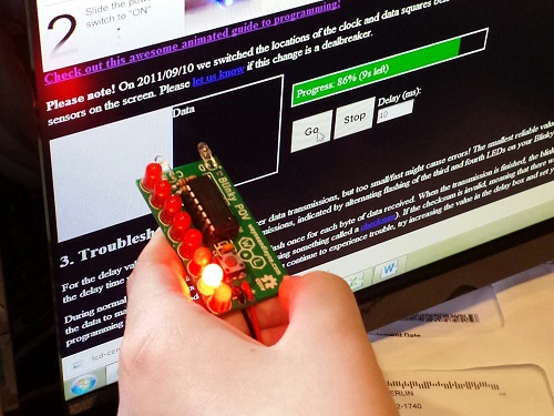
My oldest daughter Alice has an occasional interest in electronics, and as her dad I try to encourage her without becoming too annoying. We’ve done some past projects like Snap Circuits experiments, building a Drawdio pen, and constructing an animated Halloween LED display. Recently we had a chance to build a Blinky POV from Wayne and Lane. Or more accurately I should say she had a chance to build it, since my role was limited to talking her through the steps and taking photos. It’s impressive what an 11-year-old can do with a soldering iron!
The main reason I selected Wayne and Lane’s Blinky POV instead of another similar one was the novel method used to program it. Instead of a PIC programmer, a serial connection, or some other conventional interface, it uses a pair of photo sensors to program new messages using flashes of light. Go to the Blinky Programmer web page, design some pixel or text-based messages, and click “go”. A clever bit of javascript flashes two squares on the screen, and when the Blinky POV is held near these flashing squares, it reprograms the stored messages in about 30-60 seconds. In our experience this method was very reliable, and much less hassle than dealing with virtual serial ports or other wired interfaces. And it actually made programming fun – like magic! The web page interface is surprisingly versatile, too. You can design pixel art or text messages, adjust the scrolling speed, switch between multiple stored messages, and define what should happen at the end of each message.
This is starting to sound like a Wayne and Lane commercial, so I should probably add that I have no affiliation with them other than being a satisfied customer. If there’s a young builder in your life who might enjoy a simple but fun-filled electronics project, give Blinky POV a try.
These adapters would definitely be indispensable if you’re planning to do any kind of tinkering with your Arduino and whatever NXT peripherals you had in mind.
I had a lot of fun putting them together and they plugged into the breadboard very easily and sat very snugly afterwards. They’re very reasonably priced at just $4 a piece. They come with the required 82K Ohm resistor, which you will need for the pull-up.
In this review of an older kit we examine the aptly-named “Mini Stereo Amplifier” from Dick Smith Electronics (catalogue number K5008), based on the article published in the October 1992 issue of Silicon Chip magazine.
The purpose of the kit is to offer a stereo 1W+1W amplifier for use with portable audio devices that only used headphones, such as the typical portable tape players or newly available portable CD players. I feel old just writing that. At the time it would have been quite a useful kit, paired with some inexpensive speakers the end user would have a neat and portable sound solution. So let’s get started.
Assembly
Larger kits like this one that couldn’t be retailed on hanger cards shipped in corrugated cardboard boxes that were glued shut. They looked good but as soon as a sneaky customer tore one open “to have a look” it was ruined and hard to sell:
The amplifier kit was from the time when DSE still cared about kits, so you received the sixteen page “Guide to Kit Construction” plus the kit instructions, nasty red disclaimer sheet, feedback card, plus all the required components and the obligatory coil of solder that was usually rubbish:
However the completeness of the kit is outstanding, everything is included for completion including an enclosure and handy front panel sticker:
… all the sockets, plenty of jumper wire and even the rubber feet:
The PCB is from the old-school of design – without any silk-screening or solder mask:
However the instructions are quite clear so you can figure out the component placement easily. Which brings us to that point – all the components went in with ease:
… then it was a matter of wiring in the sockets, volume potentiometer and power switch:
Instead of using a 3.5mm phono socket for power input, I used a 9V battery snap instead. The amplifier can run on voltages down to 1.8V so it will do for the limited use I have in mind for the amplifier. However in the excitement of assembly I forgot the power switch:
However it wasn’t any effort to rectify that. You will also notice three links on the PCB, which I fitted instead of making coils (more on this later). So at that point the soldering work is finished:
Now to drill out the holes on the faceplate. Instead of tapering out the slots on the side of the housing, I just drilled all the holes on the front panel:
Turns out the adhesive on the front panel sticker had lost its mojo, so I might head off and get some white-on-black tape for the label maker. However in the meanwhile we have one finished mini stereo amplifier, which reminds me of an old grade seven electronics project:
How it works
The amplifier is based on the STMicro TDA2822M (data sheet .pdf) dual low-voltage amplifier IC. In fact the circuit is a slight modification of the stereo example in the data sheet. As mentioned earlier, the benefit of this IC is that it can operate on voltates down to 1.8V, however to reach the maximum power output of 1W per channel into 8Ω loads you need a 9V supply. The output will drop to around 300 mW at 6V.
Finally the Silicon Chip design calls for a triplet of coils, one each on the stereo input wires – used to prevent the RF signal being “shunted away” from the amplifier inputs. The idea behind that was some portable radios used the headphones as an antenna, however we’ll use it with the audio out from a mobile phone so it was easier to skip hand-winding the coils and just put links in the PCB.
Using the Amplifier
The purpose of this kit was to have some sound while working in the garage, so I’ve fitted a pair of cheap 1W 8Ω speakers each to a length of wire and a 3.5mm plug as shown in the image above. And for that purpose, it works very well.
Conclusion
Another kit review over. This is a genuinely useful kit and a real shame you can’t buy one today. And again – to those who have been asking me privately, no I don’t have a secret line to some underground warehouse of old kits – just keep an eye out on ebay as they pop up now and again. Full-sized images and much more information about the kit are available on flickr.
And while you’re here – are you interested in Arduino? Check out my new book “Arduino Workshop” from No Starch Press.
In the meanwhile have fun and keep checking into tronixstuff.com. Why not follow things on twitter, Google+, subscribe for email updates or RSS using the links on the right-hand column? And join our friendly Google Group – dedicated to the projects and related items on this website. Sign up – it’s free, helpful to each other – and we can all learn something.
In this review we examine the three digit counter module kit from Altronics. The purpose of this kit is to allow you to … count things. You feed it a pulse, which it counts on the rising edge of the signal. You can have it count up or down, and each kit includes three digits.
You can add more digits, in groups of three with a maximum of thirty digits. Plus it’s based on simple digital electronics (no microcontrollers here) so there’s some learning afoot as well. Designed by Graham Cattley the kit was first described in the now-defunct (thanks Graham) January 1998 issue of Electronics Australia magazine.
Assembly
The kit arrives in the typical retail fashion:
And includes the magazine article reprint along with Altronics’ “electronics reference sheet” which covers many useful topics such as resistor colour codes, various formulae, PCB track widths, pinouts and more. There is also a small addendum which uses two extra (and included) diodes for input protection on the clock signal:
The counter is ideally designed to be mounted inside an enclosure of your own choosing, so everything required to build a working counter is included however that’s it:
No IC sockets, however I decided to live dangerously and not use them – the ICs are common and easily found. The PCBs have a good solder mask and silk screen:
With four PCBs (one each for a digit control and one for the displays) the best way to start was to get the common parts out of the way and fitted, such as the current-limiting resistors, links, ICs, capacitors and the display module. The supplied current-limiting resistors are for use with a 9V DC supply, however details for other values are provided in the instructions:
At this point you put one of the control boards aside, and then start fitting the other two to the display board. This involves holding the two at ninety degrees then soldering the PCB pads to the SIL pins on the back of the display board. Starting with the control board for the hundreds digit first:
… at this stage you can power the board for a quick test:
… then fit the other control board for the tens digit and repeat:
Now it’s time to work with the third control board. This one looks after the one’s column and also a few features of the board. Several functions such as display blanking, latch (freeze the display while still counting) and gate (start or stop counting) can be controlled and require resistors fitted to this board which are detailed in the instructions.
Finally, several lengths of wire (included) are soldered to this board so that they can run through the other two to carry signals such as 5V, GND, latch, reset, gate and so on:
These wires can then be pulled through and soldered to the matching pads once the last board has been soldered to the display board:
You also need to run separate wires between the carry-out and clock-in pins between the digit control boards (the curved ones between the PCBs):
For real-life use you also need some robust connections for the power, clock, reset lines, etc., however for demonstration use I just used alligator clips. Once completed a quick power-up showed the LEDs all working:
How it works
Each digit is driven by a common IC pairing – the 4029 (data sheet) is a presettable up/down counter with a BCD (binary-coded decimal) output which feeds a 4511 (data sheet) that converts the BCD signal into outputs for a 7-segment LED display. You can count at any readable speed, and I threw a 2 kHz square-wave at the counter and it didn’t miss a beat. By default the units count upwards, however by setting one pin on the board LOW you can count downwards.
Operation
Using the counters is a simple matter of connecting power, the signal to count and deciding upon display blanking and the direction of counting. Here’s a quick video of counting up, and here it is counting back down.
Conclusion
This is a neat kit that can be used to count pulses from almost anything. Although some care needs to be taken when soldering, this isn’t anything that cannot be overcome without a little patience and diligence. So if you need to count something, get one ore more of these kits from Altronics. Full-sized images are available on flickr. And while you’re here – are you interested in Arduino? Check out my new book “Arduino Workshop” from No Starch Press – also shortly available from Altronics.
In the meanwhile have fun and keep checking into tronixstuff.com. Why not follow things on twitter, Google+, subscribe for email updates or RSS using the links on the right-hand column? And join our friendly Google Group – dedicated to the projects and related items on this website. Sign up – it’s free, helpful to each other – and we can all learn something.
This is the second in a series of tutorials examining various uses of the Arduino Yún. In this article we’ll examine how your Arduino Yún can send data that it captures from the analogue and digital inputs and a real-time clock IC to an online Google Docs spreadsheet. Doing so gives you a neat and inexpensive method of capturing data in real-time and having the ability to analyse the data from almost anywhere, and export it with very little effort.
Getting Started
If you haven’t already done so, ensure your Arduino Yún can connect to your network via WiFi or cable – and get a Temboo account (we run through this here). And you need (at the time of writing) IDE version 1.5.4 which can be downloaded from the Arduino website. Finally, you will need a Google account, so if you don’t have one – sign up here.
Testing the Arduino Yún-Google Docs connection
In this first example we’ll run through the sketch provided by Temboo so you can confirm everything works as it should. First of all, create a spreadsheet in Google Docs. Call it “ArduinoData” and label the first two columns as “time” and “sensor”, as shown in the screen shot below:
Always label the required columns. You can call them whatever you need. For new Google users, the URL shown in my example will be different to yours. Next, copy the following sketch to the IDE:
/*
  SendDataToGoogleSpreadsheet

  Demonstrates appending a row of data to a Google spreadsheet from the Arduino Yun
  using the Temboo Arduino Yun SDK.

  This example code is in the public domain.

*/

#include <Bridge.h>
#include <Temboo.h>
#include "TembooAccount.h" // contains Temboo account information

/*** SUBSTITUTE YOUR VALUES BELOW: ***/

// Note that for additional security and reusability, you could
// use #define statements to specify these values in a .h file.

const String GOOGLE_USERNAME = "your-google-username";
const String GOOGLE_PASSWORD = "your-google-password";

// the title of the spreadsheet you want to send data to
// (Note that this must actually be the title of a Google spreadsheet
// that exists in your Google Drive/Docs account, and is configured
// as described above.)
const String SPREADSHEET_TITLE = "your-spreadsheet-title";

const unsigned long RUN_INTERVAL_MILLIS = 60000; // how often to run the Choreo (in milliseconds)

// the last time we ran the Choreo
// (initialized to 60 seconds ago so the
// Choreo is run immediately when we start up)
unsigned long lastRun = (unsigned long)-60000;

void setup() {

  // for debugging, wait until a serial console is connected
  Serial.begin(9600);
  delay(4000);
  while(!Serial);

  Serial.print("Initializing the bridge...");
  Bridge.begin();
  Serial.println("Done");
}

void loop()
{
  // get the number of milliseconds this sketch has been running
  unsigned long now = millis();

  // run again if it's been 60 seconds since we last ran
  if (now - lastRun >= RUN_INTERVAL_MILLIS) {

    // remember 'now' as the last time we ran the choreo
    lastRun = now;

    Serial.println("Getting sensor value...");

    // get the value we want to append to our spreadsheet
    unsigned long sensorValue = getSensorValue();

    Serial.println("Appending value to spreadsheet...");

    // we need a Process object to send a Choreo request to Temboo
    TembooChoreo AppendRowChoreo;

    // invoke the Temboo client
    // NOTE that the client must be reinvoked and repopulated with
    // appropriate arguments each time its run() method is called.
    AppendRowChoreo.begin();

    // set Temboo account credentials
    AppendRowChoreo.setAccountName(TEMBOO_ACCOUNT);
    AppendRowChoreo.setAppKeyName(TEMBOO_APP_KEY_NAME);
    AppendRowChoreo.setAppKey(TEMBOO_APP_KEY);

    // identify the Temboo Library choreo to run (Google > Spreadsheets > AppendRow)
    AppendRowChoreo.setChoreo("/Library/Google/Spreadsheets/AppendRow");

    // set the required Choreo inputs
    // see https://www.temboo.com/library/Library/Google/Spreadsheets/AppendRow/
    // for complete details about the inputs for this Choreo

    // your Google username (usually your email address)
    AppendRowChoreo.addInput("Username", GOOGLE_USERNAME);

    // your Google account password
    AppendRowChoreo.addInput("Password", GOOGLE_PASSWORD);

    // the title of the spreadsheet you want to append to
    AppendRowChoreo.addInput("SpreadsheetTitle", SPREADSHEET_TITLE);

    // convert the time and sensor values to a comma separated string
    String rowData(now);
    rowData += ",";
    rowData += sensorValue;

    // add the RowData input item
    AppendRowChoreo.addInput("RowData", rowData);

    // run the Choreo and wait for the results
    // The return code (returnCode) will indicate success or failure
    unsigned int returnCode = AppendRowChoreo.run();

    // return code of zero (0) means success
    if (returnCode == 0) {
      Serial.println("Success! Appended " + rowData);
      Serial.println("");
    } else {
      // return code of anything other than zero means failure
      // read and display any error messages
      while (AppendRowChoreo.available()) {
        char c = AppendRowChoreo.read();
        Serial.print(c);
      }
    }

    AppendRowChoreo.close();
  }
}

// this function simulates reading the value of a sensor
unsigned long getSensorValue() {
  return analogRead(A0);
}
Now look for the following two lines in the sketch:
This is where you put your Google account username and password. For example, if your Google account is “CI5@gmail.com” and password “RS2000Escort” the two lines will be:
Finally, create your header file by copying the the header file data from here (after logging to Temboo) into a text file and saving it with the name TembooAccount.h in the same folder as your sketch from above. You know this has been successful when opening the sketch, as you will see the header file in a second tab, for example:
Finally, save and upload your sketch to the Arduino Yún. After a moment or two it will send values to the spreadsheet, and repeat this every sixty seconds – for example:
If your Yún is connected via USB you can also watch the status via the serial monitor.
One really super-cool and convenient feature of using Google Docs is that you can access it from almost anywhere. Desktop, tablet, mobile… and it updates in real-time:
So with your Yún you can capture data and view it from anywhere you can access the Internet. Now let’s do just that.
Sending your own data from the Arduino Yún to a Google Docs Spreadsheet
In this example we’ll demonstrate sending three types of data:
With these types of data you should be able to represent all manner of things. We use the RTC as the time and date from it will match when the data was captured, not when the data was written to the spreadsheet. If you don’t have a DS3232 you can also use a DS1307.
If you’re not familiar with these parts and the required code please review this tutorial. When connecting your RTC – please note that SDA (data) is D2 and SCL (clock) is D3 on the Yún.
The sketch for this example is a modified version of the previous sketch, except we have more data to send. The data is captured into variables from the line:
// get the values from A0 to A3 and D7, D8
You can send whatever data you like, as long as it is all appended to a String by the name of rowdata. When you want to use a new column in the spreadsheet, simply append a comma “,” between the data in the string. In other words, you’re creating a string of CSV (comma-separated values) data. You can see this process happen from the line that has the comment:
// CSV creation starts here!
in the example sketch that follows shortly. Finally, you can alter the update rate of the sketch – it’s set to every 60 seconds, however you can change this by altering the 60000 (milliseconds) in the following line:
const unsigned long RUN_INTERVAL_MILLIS = 60000;
Don’t forget that each update costs you a call and some data from your Temboo account – you only get so many for free then you have to pay for more. Check your Temboo account for more details.
So without further ado, the following sketch will write the values read from A0~A3, the status of D7 and D8 (1 for HIGH, 0 for LOW) along with the current date and time to the spreadsheet. Don’t forget to update the password, username and so on as you did for the first example sketch:
#include <Bridge.h>
#include <Temboo.h>
#include "TembooAccount.h" // contains Temboo account information
#include "Wire.h"
#define DS3232_I2C_ADDRESS 0x68
unsigned long analog0, analog1, analog2, analog3;
int digital7 = 7;
int digital8 = 8;
boolean d7, d8;
byte second, minute, hour, dayOfWeek, dayOfMonth, month, year; // for RTC
const String GOOGLE_USERNAME = "your-google-username";
const String GOOGLE_PASSWORD = "your-google-password";
const String SPREADSHEET_TITLE = "your-spreadsheet-title";
// update interval in milliseconds (every minute would be 60000)
const unsigned long RUN_INTERVAL_MILLIS = 60000;
unsigned long lastRun = (unsigned long)-60000;
void setup()
{
// activate I2C bus
Wire.begin();
// for debugging, wait until a serial console is connected
Serial.begin(9600);
delay(4000);
while(!Serial);
Serial.print("Initializing the bridge...");
Bridge.begin();
Serial.println("Done");
// Set up digital inputs to monitor
pinMode(digital7, INPUT);
pinMode(digital8, INPUT);
}
// for RTC
// Convert normal decimal numbers to binary coded decimal
byte decToBcd(byte val)
{
return ( (val/10*16) + (val%10) );
}
// Convert binary coded decimal to normal decimal numbers
byte bcdToDec(byte val)
{
return ( (val/16*10) + (val%16) );
}
void readDS3232time(byte *second,
byte *minute,
byte *hour,
byte *dayOfWeek,
byte *dayOfMonth,
byte *month,
byte *year)
{
Wire.beginTransmission(DS3232_I2C_ADDRESS);
Wire.write(0); // set DS3232 register pointer to 00h
Wire.endTransmission();
Wire.requestFrom(DS3232_I2C_ADDRESS, 7); // request 7 bytes of data from DS3232 starting from register 00h
// A few of these need masks because certain bits are control bits
*second = bcdToDec(Wire.read() & 0x7f);
*minute = bcdToDec(Wire.read());
*hour = bcdToDec(Wire.read() & 0x3f); // Need to change this if 12 hour am/pm
*dayOfWeek = bcdToDec(Wire.read());
*dayOfMonth = bcdToDec(Wire.read());
*month = bcdToDec(Wire.read());
*year = bcdToDec(Wire.read());
}
void setDS3232time(byte second, byte minute, byte hour, byte dayOfWeek, byte dayOfMonth, byte month, byte year)
// sets time and date data to DS3232
{
Wire.beginTransmission(DS3232_I2C_ADDRESS);
Wire.write(0); // sends 00h - seconds register
Wire.write(decToBcd(second)); // set seconds
Wire.write(decToBcd(minute)); // set minutes
Wire.write(decToBcd(hour)); // set hours
Wire.write(decToBcd(dayOfWeek)); // set day of week (1=Sunday, 7=Saturday)
Wire.write(decToBcd(dayOfMonth)); // set date (1~31)
Wire.write(decToBcd(month)); // set month
Wire.write(decToBcd(year)); // set year (0~99)
Wire.endTransmission();
}
void loop()
{
// get the number of milliseconds this sketch has been running
unsigned long now = millis();
// run again if it's been 60 seconds since we last ran
if (now - lastRun >= RUN_INTERVAL_MILLIS) {
// remember 'now' as the last time we ran the choreo
lastRun = now;
Serial.println("Getting sensor values...");
// get the values from A0 to A3 and D7, D8
analog0 = analogRead(0);
analog1 = analogRead(1);
analog2 = analogRead(2);
analog3 = analogRead(3);
d7 = digitalRead(digital7);
d8 = digitalRead(digital8);
Serial.println("Appending value to spreadsheet...");
// we need a Process object to send a Choreo request to Temboo
TembooChoreo AppendRowChoreo;
// invoke the Temboo client
// NOTE that the client must be reinvoked and repopulated with
// appropriate arguments each time its run() method is called.
AppendRowChoreo.begin();
// set Temboo account credentials
AppendRowChoreo.setAccountName(TEMBOO_ACCOUNT);
AppendRowChoreo.setAppKeyName(TEMBOO_APP_KEY_NAME);
AppendRowChoreo.setAppKey(TEMBOO_APP_KEY);
// identify the Temboo Library choreo to run (Google > Spreadsheets > AppendRow)
AppendRowChoreo.setChoreo("/Library/Google/Spreadsheets/AppendRow");
// your Google username (usually your email address)
AppendRowChoreo.addInput("Username", GOOGLE_USERNAME);
// your Google account password
AppendRowChoreo.addInput("Password", GOOGLE_PASSWORD);
// the title of the spreadsheet you want to append to
AppendRowChoreo.addInput("SpreadsheetTitle", SPREADSHEET_TITLE);
// get time and date from RTC
readDS3232time(&second, &minute, &hour, &dayOfWeek, &dayOfMonth, &month, &year);
// smoosh all the sensor, date and time data into a String
// CSV creation starts here!
String rowData(analog0);
rowData += ",";
rowData += analog1;
rowData += ",";
rowData += analog2;
rowData += ",";
rowData += analog3;
rowData += ",";
rowData += d7;
rowData += ",";
rowData += d8;
rowData += ",";
// insert date
rowData += dayOfMonth;
rowData += "/";
rowData += month;
rowData += "/20";
rowData += year;
rowData += ",";
// insert time
rowData += hour;
if (minute<10)
{
rowData += "0";
}
rowData += minute;
rowData += ".";
if (second<10)
{
rowData += "0";
}
rowData += second;
rowData += "h";
// add the RowData input item
AppendRowChoreo.addInput("RowData", rowData);
// run the Choreo and wait for the results
// The return code (returnCode) will indicate success or failure
unsigned int returnCode = AppendRowChoreo.run();
// return code of zero (0) means success
if (returnCode == 0) {
Serial.println("Success! Appended " + rowData);
Serial.println("");
} else {
// return code of anything other than zero means failure
// read and display any error messages
while (AppendRowChoreo.available()) {
char c = AppendRowChoreo.read();
Serial.print(c);
}
}
AppendRowChoreo.close();
}
}
… which in our example resulted with the following:
… and here is a video that shows how the spreadsheet updates in real time across multiple devices:
Conclusion
It’s no secret that the Yún isn’t the cheapest devleopment board around, however the ease of use as demonstrated in this tutorial shows that the time saved in setup and application is more than worth the purchase price of the board and extra Temboo credits if required.
And if you’re interested in learning more about Arduino, or want to introduce someone else to the interesting world of Arduino – check out my book (now in a third printing!) “Arduino Workshop” from No Starch Press.
In the meanwhile have fun and keep checking into tronixstuff.com. Why not follow things on twitter, Google+, subscribe for email updates or RSS using the links on the right-hand column? And join our friendly Google Group – dedicated to the projects and related items on this website. Sign up – it’s free, helpful to each other – and we can all learn something.
In this review of an older kit (circa 1993~1997) we examine the Diesel Sound Simulator for Model Railroads kit from (the now defunct) Dick Smith Electronics, based on the article published in the December 1992 issue of Silicon Chip magazine.
The purpose of this kit is to give you a small circuit which can fit in a HO scale (or larger) locomotive, or hidden underneath the layout – that can emulate the rumbling of a diesel-electric locomotive to increase the realism of a train. However the kit is designed for use with a PWM train controller (also devised by Silicon Chip!) so not for the simple direct-DC drive layouts.
Assembly
The diesel sound kit was from the time when DSE still cared about kits, so you received the sixteen page “Guide to Kit Construction” plus the kit instructions, nasty red disclaimer sheet, feedback card, plus all the required components and the obligatory coil of solder that was usually rubbish:
Everything required to get going is included, except IC sockets. My theory is it’s cheaper to use your own sockets than source older CMOS/TTL later on if you want to reuse the ICs, so sockets are now mandatory here:
The PCB is from the old school of “figure-it-out-yourself”, no fancy silk-screening here:
Notice the five horizontal pads between the two ICs – these were for wire bridges in case you needed to break the PCB in two to fit inside your locomotive.
Actual assembly was straight-forward, all the components went in without any issues. Having two links under IC2 was a little annoying, however a short while later the PCB was finished and the speaker attached:
How it works
As mentioned earlier this diesel sound kit was designed for use with the Silicon Chip train PWM controller, so the design is a little different than expected. It can handle a voltage of around 20 V, and the sound is determined by the speed of the locomotive.
The speed is determined by the back EMF measured from the motor – and (from the manual) this is the voltage produced by the motor which opposes the current flow through it and this voltage is directly proportional to speed.
Not having a 20V DC PWM supply laying about I knocked up an Arduino to PWM a 20V DC supply via an N-MOSFET module and experimented with the duty cycle to see what sort of noises could be possible. The output was affected somewhat by the supply voltage, however seemed a little higher in pitch than expected.
You can listen to the results in the following video:
I reckon the sound from around the twenty second mark isn’t a bad idle noise, however in general not that great. The results will ultimately be a function of a lower duty-cycle than I could create at the time and the values of R1 and R2 used in the kit.
Conclusion
Another kit review over. With some time spent experimenting you could generate the required diesel sounds, a Paxman-Valenta it isn’t… but it was a fun kit and I’m sure it was well-received at the time. To those who have been asking me privately, no I don’t have a secret line to some underground warehouse of old kits – just keep an eye out on ebay and they pop up now and again. Full-sized images and much more information about the kit are available on flickr.
And while you’re here – are you interested in Arduino? Check out my new book “Arduino Workshop” from No Starch Press.
In the meanwhile have fun and keep checking into tronixstuff.com. Why not follow things on twitter, Google+, subscribe for email updates or RSS using the links on the right-hand column? And join our friendly Google Group – dedicated to the projects and related items on this website. Sign up – it’s free, helpful to each other – and we can all learn something.
In this review we examine the Pocket Oscillator Kit from Altronics, based on an design from (the now defunct) February and March 1989 editions of Electronics Australia magazine. The purpose of this oscillator is to give you a high quality, portable square or sine wave generator that can be used to test audio equipment, speaker response, fool about with oscilloscopes (!), and so on. The prototype basic specifications are as follows:
Frequency range: 41~1082 Hz and 735 Hz~18.1 kHz
Output: 1.27V RMS sine, 1.45V peak square
Load: 1.0V RMS sine into 330 Ω
Distortion: 0.16% THD at 1 kHz
Assembly
The kit is packaged in typical form, without any surprises:
In the usual Altronics fashion, the instructions are accompanied with a neat “electronics reference sheet” which covers many useful topics such as resistor colour codes, various formulae, PCB track widths, pinouts and more. The kit instructions are based on the original magazine article and include a small addendum which isn’t any problem.
Unlike some kits, everything is included to create a finished product (except for the IC socket):
… including a nice enclosure which has the control instructions screen-printed on the lid…
However at this point I think the definition of a “pocket” is the same used by Sir Clive Sinclair when he had those pocket televisions. At this time I won’t use the enclosure as my drill press is in storage, however look forward to fitting the kit within at a later point. The PCB has a neat solder mask and silk screen:
Assembly was pretty straight forward, the original design has tried to minimise PCB real-estate, so all the resistors are mounted vertically. The signal diodes take this a step further – each pair needs to be soldered together:
… then the pair is also mounted vertically:
However it all works in the end. The rest of the circuit went together well, and we used our own IC socket for the opamp:
From this point you need to wire up the power, switches and potentiometers:
… and consider mounting the whole lot in the enclosure (or before assembly!):
However as mentioned earlier, I just went for the open octopus method for time being:
How it works
The oscillator is based around the Texas Instruments TL064 opamp, and due to copyright I can’t give you the schematic. For complete details on the oscillator, either purchase the kit or locate the February and March 1989 edition of Electronics Australia magazine. However the waveforms from the oscillator looked good (as far as they can on a DSO):
Conclusion
The oscillator works well, however the PCB layout could have been a little lot easier on the end-user. It’s time for a redesign, possibly put all the contacts for external switches around the perimeter – and allow space for the diodes to lay normally. Nevertheless – this is a neat kit, and still quite popular after all these years. For the price you get a few hours of kit fun and a useful piece of test equipment. So if you’re into audio or experimenting, check it out. Full-sized images are available on flickr.
And while you’re here – are you interested in Arduino? Check out my new book “Arduino Workshop” from No Starch Press – also shortly available from Altronics.
In the meanwhile have fun and keep checking into tronixstuff.com. Why not follow things on twitter, Google+, subscribe for email updates or RSS using the links on the right-hand column? And join our friendly Google Group – dedicated to the projects and related items on this website. Sign up – it’s free, helpful to each other – and we can all learn something.
[Note - kit purchased without notifying the supplier]
After helping many people get started with the world of Arduino and electronics, we still find a small percentage of people who are turned off by the concept of programming or have trouble breaking larger tasks into smaller ones with regards to writing algorithms for their code/sketch.
So after being introduced to a new graphical programming tool called “Ardublock“, we were excited about the possibilities wanted to share it with our readers. Ardublock provides a truly graphical and non-coding solution to controlling an Arduino, that is an open-source product and thus free to download and try for yourself.
Installation
Ardublock is a Java application that runs from inside the Arduino IDE, which can be downloaded from here. It’s only one file, that needs to be placed in a new folder in the Arduino IDE. The folder names must be the same as shown below:
Once you’ve copied the file, simply open the Arduino IDE and select Ardublock from the Tools menu:
From which point a new window appears – the Ardublock “development environment”:
Using Ardublock
It’s quite simple – you simply select the required function from the menu on the left and drag it into the large area on the right. For a quick example where we blink the onboard LED on and off – watch the following video:
The following image is the screen capture of the program from the video:
As you can see the “blocks” just fit together, and parameters can be changed with the right mouse button. After a few moments experimenting with the Ardublock software you will have the hang of it in no time at all.
And thus you can demonstrate it to other people and show them how easy it is. And there is much more than just digital output controls, all the functions you’re used to including I2C, variables, constants, servos, tone and more are available.
The only technical thing you need to demonstrate is that the Arduino IDE needs to stay open in the background – as once you have finished creating your program, Ardublock creates the required real Arduino sketch back in the IDE and uploads it to the board.
This is also a neat function – the user can then compare their Ardublock program against the actual sketch, and hopefully after a short duration the user will have the confidence to move on with normal coding.
Conclusion
Ardublock provides a very simple method of controlling an Arduino, and makes a great starting point for teaching the coding-averse, very young people or the cognitively-challenged. It’s open source, integrates well with the official IDE and works as described – so give it a go.
And if you enjoyed this review, or want to introduce someone else to the interesting world of Arduino – check out my book (now in a third printing!) “Arduino Workshop” from No Starch Press.
In the meanwhile have fun and keep checking into tronixstuff.com. Why not follow things on twitter, Google+, subscribe for email updates or RSS using the links on the right-hand column? And join our friendly Google Group – dedicated to the projects and related items on this website. Sign up – it’s free, helpful to each other – and we can all learn something.
Planet Arduino is, or at the moment is wishing to become, an aggregation of public weblogs from around the world written by people who develop, play, think on Arduino platform and his son. The opinions expressed in those weblogs and hence this aggregation are those of the original authors. Entries on this page are owned by their authors. We do not edit, endorse or vouch for the contents of individual posts. For more information about Arduino please visit www.arduino.cc
You are currently browsing the archives for the review category.