25
Kit Review – FriedCircuits LED Matrix Link
arduino, as1107, friedcircuits, kit, kit review, LED, LED matrix, matrix, MAX7219, mobile will, module, review, tronixstuff, tutorial Comments Off on Kit Review – FriedCircuits LED Matrix Link
Introduction
Time for another kit review, and in this instalment we’ve received some LED matrix modules and a matching Arduino-compatible controller board from friedcircuits.us. Behind the name is William Garrido – who some of you may know as “mobile will” from following his blog. Over time William has created a range of small and useful products, which are now available on the tindie online store.
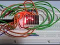
The system comprises of two modules. The first is a small Arduino-compatible board with an ATmega328P microcontroller – the LED matrix master. It’s quite small and is designed to be the start of a chain of matching LED matrix link boards. Each of these holds an 8×8 LED matrix and is controlled by the AS1107 LED driver IC. This is a direct replacement IC for the popular MAX7219, works exactly the same and is a great find instead of using knock-off MAX7219s. You can chain up to 8 matrix modules from the one controller. We received a matrix master and two matrix link boards to examine, which arrived in solid packaging a fun Tindie sticker:

Assembly
All the surface-mount soldering is done in advance, leaving you with some simple through-hole soldering for the LED matrix and the connectors between each module. The PCBs are clearly labelled with the silk screen and have mounting holes for permanent installations:


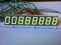
So after a few minutes of soldering it’s time to get the blinking on:

You may have noticed by now that the master board doesn’t have a USB socket, so you’ll need a 5V FTDI cable or a USBasp programmer to upload your Arduino sketches or AVR .hex file to get things moving.
Controlling a matrix or more
As the system is basically an Arduino-compatible with one or more MAX7219-compatible modules you can find all sorts of example sketches to experiment with. If you haven’t used a MAX7219/AS1107 before there are a couple of starting points including the Arduino library and another random tutorial. Using an example sketch on the Arduino forum by member “danigom“, and after checking the data, clock and load pins it was ready to go. Here’s the sketch for your consideration:
/* Program is currently hard coded to drive 4x MAX7219 chips
though altering code to drive upto 7 chips is trivial
Orginal sketch by Arduino forum member "danigom"
http://forum.arduino.cc/index.php?action=profile;u=188950
*/
//We always have to include the libraries
#include <avr/pgmspace.h>
#include <LedControl.h>
// *CONSTANTS
const int DIN = 12; //DataIn pin (18)
const int CLK = 11; //Clock pin (17)
const int LOAD = 10; //Load pin (16)
const int numDevices = 2; //Number of MAX7219 LED Driver Chips (1-8)
const long scrollDelay = 70;
prog_uchar font5x7 [] PROGMEM = { //Numeric Font Matrix (Arranged as 7x font data + 1x kerning data)
B00000000, //Space (Char 0x20)
B00000000,
B00000000,
B00000000,
B00000000,
B00000000,
B00000000,
6,
B10000000, //!
B10000000,
B10000000,
B10000000,
B00000000,
B00000000,
B10000000,
2,
B10100000, //"
B10100000,
B10100000,
B00000000,
B00000000,
B00000000,
B00000000,
4,
B01010000, //#
B01010000,
B11111000,
B01010000,
B11111000,
B01010000,
B01010000,
6,
B00100000, //$
B01111000,
B10100000,
B01110000,
B00101000,
B11110000,
B00100000,
6,
B11000000, //%
B11001000,
B00010000,
B00100000,
B01000000,
B10011000,
B00011000,
6,
B01100000, //&
B10010000,
B10100000,
B01000000,
B10101000,
B10010000,
B01101000,
6,
B11000000, //'
B01000000,
B10000000,
B00000000,
B00000000,
B00000000,
B00000000,
3,
B00100000, //(
B01000000,
B10000000,
B10000000,
B10000000,
B01000000,
B00100000,
4,
B10000000, //)
B01000000,
B00100000,
B00100000,
B00100000,
B01000000,
B10000000,
4,
B00000000, //*
B00100000,
B10101000,
B01110000,
B10101000,
B00100000,
B00000000,
6,
B00000000, //+
B00100000,
B00100000,
B11111000,
B00100000,
B00100000,
B00000000,
6,
B00000000, //,
B00000000,
B00000000,
B00000000,
B11000000,
B01000000,
B10000000,
3,
B00000000, //-
B00000000,
B11111000,
B00000000,
B00000000,
B00000000,
B00000000,
6,
B00000000, //.
B00000000,
B00000000,
B00000000,
B00000000,
B11000000,
B11000000,
3,
B00000000, ///
B00001000,
B00010000,
B00100000,
B01000000,
B10000000,
B00000000,
6,
B01110000, //0
B10001000,
B10011000,
B10101000,
B11001000,
B10001000,
B01110000,
6,
B01000000, //1
B11000000,
B01000000,
B01000000,
B01000000,
B01000000,
B11100000,
4,
B01110000, //2
B10001000,
B00001000,
B00010000,
B00100000,
B01000000,
B11111000,
6,
B11111000, //3
B00010000,
B00100000,
B00010000,
B00001000,
B10001000,
B01110000,
6,
B00010000, //4
B00110000,
B01010000,
B10010000,
B11111000,
B00010000,
B00010000,
6,
B11111000, //5
B10000000,
B11110000,
B00001000,
B00001000,
B10001000,
B01110000,
6,
B00110000, //6
B01000000,
B10000000,
B11110000,
B10001000,
B10001000,
B01110000,
6,
B11111000, //7
B10001000,
B00001000,
B00010000,
B00100000,
B00100000,
B00100000,
6,
B01110000, //8
B10001000,
B10001000,
B01110000,
B10001000,
B10001000,
B01110000,
6,
B01110000, //9
B10001000,
B10001000,
B01111000,
B00001000,
B00010000,
B01100000,
6,
B00000000, //:
B11000000,
B11000000,
B00000000,
B11000000,
B11000000,
B00000000,
3,
B00000000, //;
B11000000,
B11000000,
B00000000,
B11000000,
B01000000,
B10000000,
3,
B00010000, //<
B00100000,
B01000000,
B10000000,
B01000000,
B00100000,
B00010000,
5,
B00000000, //=
B00000000,
B11111000,
B00000000,
B11111000,
B00000000,
B00000000,
6,
B10000000, //>
B01000000,
B00100000,
B00010000,
B00100000,
B01000000,
B10000000,
5,
B01110000, //?
B10001000,
B00001000,
B00010000,
B00100000,
B00000000,
B00100000,
6,
B01110000, //@
B10001000,
B00001000,
B01101000,
B10101000,
B10101000,
B01110000,
6,
B01110000, //A
B10001000,
B10001000,
B10001000,
B11111000,
B10001000,
B10001000,
6,
B11110000, //B
B10001000,
B10001000,
B11110000,
B10001000,
B10001000,
B11110000,
6,
B01110000, //C
B10001000,
B10000000,
B10000000,
B10000000,
B10001000,
B01110000,
6,
B11100000, //D
B10010000,
B10001000,
B10001000,
B10001000,
B10010000,
B11100000,
6,
B11111000, //E
B10000000,
B10000000,
B11110000,
B10000000,
B10000000,
B11111000,
6,
B11111000, //F
B10000000,
B10000000,
B11110000,
B10000000,
B10000000,
B10000000,
6,
B01110000, //G
B10001000,
B10000000,
B10111000,
B10001000,
B10001000,
B01111000,
6,
B10001000, //H
B10001000,
B10001000,
B11111000,
B10001000,
B10001000,
B10001000,
6,
B11100000, //I
B01000000,
B01000000,
B01000000,
B01000000,
B01000000,
B11100000,
4,
B00111000, //J
B00010000,
B00010000,
B00010000,
B00010000,
B10010000,
B01100000,
6,
B10001000, //K
B10010000,
B10100000,
B11000000,
B10100000,
B10010000,
B10001000,
6,
B10000000, //L
B10000000,
B10000000,
B10000000,
B10000000,
B10000000,
B11111000,
6,
B10001000, //M
B11011000,
B10101000,
B10101000,
B10001000,
B10001000,
B10001000,
6,
B10001000, //N
B10001000,
B11001000,
B10101000,
B10011000,
B10001000,
B10001000,
6,
B01110000, //O
B10001000,
B10001000,
B10001000,
B10001000,
B10001000,
B01110000,
6,
B11110000, //P
B10001000,
B10001000,
B11110000,
B10000000,
B10000000,
B10000000,
6,
B01110000, //Q
B10001000,
B10001000,
B10001000,
B10101000,
B10010000,
B01101000,
6,
B11110000, //R
B10001000,
B10001000,
B11110000,
B10100000,
B10010000,
B10001000,
6,
B01111000, //S
B10000000,
B10000000,
B01110000,
B00001000,
B00001000,
B11110000,
6,
B11111000, //T
B00100000,
B00100000,
B00100000,
B00100000,
B00100000,
B00100000,
6,
B10001000, //U
B10001000,
B10001000,
B10001000,
B10001000,
B10001000,
B01110000,
6,
B10001000, //V
B10001000,
B10001000,
B10001000,
B10001000,
B01010000,
B00100000,
6,
B10001000, //W
B10001000,
B10001000,
B10101000,
B10101000,
B10101000,
B01010000,
6,
B10001000, //X
B10001000,
B01010000,
B00100000,
B01010000,
B10001000,
B10001000,
6,
B10001000, //Y
B10001000,
B10001000,
B01010000,
B00100000,
B00100000,
B00100000,
6,
B11111000, //Z
B00001000,
B00010000,
B00100000,
B01000000,
B10000000,
B11111000,
6,
B11100000, //[
B10000000,
B10000000,
B10000000,
B10000000,
B10000000,
B11100000,
4,
B00000000, //(Backward Slash)
B10000000,
B01000000,
B00100000,
B00010000,
B00001000,
B00000000,
6,
B11100000, //]
B00100000,
B00100000,
B00100000,
B00100000,
B00100000,
B11100000,
4,
B00100000, //^
B01010000,
B10001000,
B00000000,
B00000000,
B00000000,
B00000000,
6,
B00000000, //_
B00000000,
B00000000,
B00000000,
B00000000,
B00000000,
B11111000,
6,
B10000000, //`
B01000000,
B00100000,
B00000000,
B00000000,
B00000000,
B00000000,
4,
B00000000, //a
B00000000,
B01110000,
B00001000,
B01111000,
B10001000,
B01111000,
6,
B10000000, //b
B10000000,
B10110000,
B11001000,
B10001000,
B10001000,
B11110000,
6,
B00000000, //c
B00000000,
B01110000,
B10001000,
B10000000,
B10001000,
B01110000,
6,
B00001000, //d
B00001000,
B01101000,
B10011000,
B10001000,
B10001000,
B01111000,
6,
B00000000, //e
B00000000,
B01110000,
B10001000,
B11111000,
B10000000,
B01110000,
6,
B00110000, //f
B01001000,
B01000000,
B11100000,
B01000000,
B01000000,
B01000000,
6,
B00000000, //g
B01111000,
B10001000,
B10001000,
B01111000,
B00001000,
B01110000,
6,
B10000000, //h
B10000000,
B10110000,
B11001000,
B10001000,
B10001000,
B10001000,
6,
B01000000, //i
B00000000,
B11000000,
B01000000,
B01000000,
B01000000,
B11100000,
4,
B00010000, //j
B00000000,
B00110000,
B00010000,
B00010000,
B10010000,
B01100000,
5,
B10000000, //k
B10000000,
B10010000,
B10100000,
B11000000,
B10100000,
B10010000,
5,
B11000000, //l
B01000000,
B01000000,
B01000000,
B01000000,
B01000000,
B11100000,
4,
B00000000, //m
B00000000,
B11010000,
B10101000,
B10101000,
B10001000,
B10001000,
6,
B00000000, //n
B00000000,
B10110000,
B11001000,
B10001000,
B10001000,
B10001000,
6,
B00000000, //o
B00000000,
B01110000,
B10001000,
B10001000,
B10001000,
B01110000,
6,
B00000000, //p
B00000000,
B11110000,
B10001000,
B11110000,
B10000000,
B10000000,
6,
B00000000, //q
B00000000,
B01101000,
B10011000,
B01111000,
B00001000,
B00001000,
6,
B00000000, //r
B00000000,
B10110000,
B11001000,
B10000000,
B10000000,
B10000000,
6,
B00000000, //s
B00000000,
B01110000,
B10000000,
B01110000,
B00001000,
B11110000,
6,
B01000000, //t
B01000000,
B11100000,
B01000000,
B01000000,
B01001000,
B00110000,
6,
B00000000, //u
B00000000,
B10001000,
B10001000,
B10001000,
B10011000,
B01101000,
6,
B00000000, //v
B00000000,
B10001000,
B10001000,
B10001000,
B01010000,
B00100000,
6,
B00000000, //w
B00000000,
B10001000,
B10101000,
B10101000,
B10101000,
B01010000,
6,
B00000000, //x
B00000000,
B10001000,
B01010000,
B00100000,
B01010000,
B10001000,
6,
B00000000, //y
B00000000,
B10001000,
B10001000,
B01111000,
B00001000,
B01110000,
6,
B00000000, //z
B00000000,
B11111000,
B00010000,
B00100000,
B01000000,
B11111000,
6,
B00100000, //{
B01000000,
B01000000,
B10000000,
B01000000,
B01000000,
B00100000,
4,
B10000000, //|
B10000000,
B10000000,
B10000000,
B10000000,
B10000000,
B10000000,
2,
B10000000, //}
B01000000,
B01000000,
B00100000,
B01000000,
B01000000,
B10000000,
4,
B00000000, //~
B00000000,
B00000000,
B01101000,
B10010000,
B00000000,
B00000000,
6,
B01100000, // (Char 0x7F)
B10010000,
B10010000,
B01100000,
B00000000,
B00000000,
B00000000,
5
};
prog_uchar scrollText[] PROGMEM ={
" THE QUICK BROWN FOX JUMPED OVER THE LAZY DOG 1234567890 the quick brown fox jumped over the lazy dog \0"};
// * GLOBAL VARIABLES
unsigned long bufferLong [14] = {0}; //Buffer for scrolling text
LedControl lc=LedControl(DIN,CLK,LOAD,numDevices);
void setup(){
for (int x=0; x<numDevices; x++){
lc.shutdown(x,false); //The MAX72XX is in power-saving mode on startup
lc.setIntensity(x,8); // Set the brightness to default value
lc.clearDisplay(x); // and clear the display
}
}
void loop(){
scrollMessage(scrollText);
scrollFont();
}
void scrollFont() {
for (int counter=0x20;counter<0x80;counter++){
loadBufferLong(counter);
delay(500);
}
}
// Scroll Message
void scrollMessage(prog_uchar * messageString) {
int counter = 0;
int myChar=0;
do {
// read back a char
myChar = pgm_read_byte_near(messageString + counter);
if (myChar != 0){
loadBufferLong(myChar);
}
counter++;
}
while (myChar != 0);
}
// Load character into scroll buffer
void loadBufferLong(int ascii){
if (ascii >= 0x20 && ascii <=0x7f){
for (int a=0;a<7;a++){ // Loop 7 times for a 5x7 font
unsigned long c = pgm_read_byte_near(font5x7 + ((ascii - 0x20) * 8) + a); // Index into character table to get row data
unsigned long x = bufferLong [a*2]; // Load current scroll buffer
x = x | c; // OR the new character onto end of current
bufferLong [a*2] = x; // Store in buffer
}
byte count = pgm_read_byte_near(font5x7 +((ascii - 0x20) * 8) + 7); // Index into character table for kerning data
for (byte x=0; x<count;x++){
rotateBufferLong();
printBufferLong();
delay(scrollDelay);
}
}
}
// Rotate the buffer
void rotateBufferLong(){
for (int a=0;a<7;a++){ // Loop 7 times for a 5x7 font
unsigned long x = bufferLong [a*2]; // Get low buffer entry
byte b = bitRead(x,31); // Copy high order bit that gets lost in rotation
x = x<<1; // Rotate left one bit
bufferLong [a*2] = x; // Store new low buffer
x = bufferLong [a*2+1]; // Get high buffer entry
x = x<<1; // Rotate left one bit
bitWrite(x,0,b); // Store saved bit
bufferLong [a*2+1] = x; // Store new high buffer
}
}
// Display Buffer on LED matrix
void printBufferLong(){
for (int a=0;a<7;a++){ // Loop 7 times for a 5x7 font
unsigned long x = bufferLong [a*2+1]; // Get high buffer entry
byte y = x; // Mask off first character
lc.setRow(3,a,y); // Send row to relevent MAX7219 chip
x = bufferLong [a*2]; // Get low buffer entry
y = (x>>24); // Mask off second character
lc.setRow(2,a,y); // Send row to relevent MAX7219 chip
y = (x>>16); // Mask off third character
lc.setRow(1,a,y); // Send row to relevent MAX7219 chip
y = (x>>8); // Mask off forth character
lc.setRow(0,a,y); // Send row to relevent MAX7219 chip
}
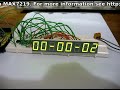
}In the following video you can see the sketch in action with two and one matrix modules:
Where to from here?
The matrix modules can find a wide range of uses, from simple fun and scrolling text to various LED matrix games, status displays and more. They also work well with the XOBXOB IoT USB-connected example. The design files are available for perusal on the friedcircuits github page. And don’t forget the matrix master board in itself is a tiny Arduino-compatible – with the full eight ADCs and digital I/O pins available. Thus you can embed this in another project if so desired.
Conclusion
The LED matrix modules are simple to use and work well together. Plus the matrix master board makes for a neat little Arduino-compatible as well. For more information and to order, visit the friedcircuits.us website. Full-sized images are on flickr. And if you made it this far – check out my new book “Arduino Workshop” from No Starch Press.

In the meanwhile have fun and keep checking into tronixstuff.com. Why not follow things on twitter, Google+, subscribe for email updates or RSS using the links on the right-hand column? And join our friendly Google Group – dedicated to the projects and related items on this website. Sign up – it’s free, helpful to each other – and we can all learn something.
[Note - kits reviewed were a promotional consideration from friedcircuits]
The post Kit Review – FriedCircuits LED Matrix Link appeared first on tronixstuff.