Posts | Comments

Planet Arduino

Archive for the ‘Atmega 2560’ Category

It might be fair to suspect that most people who are considered digital natives have very little to no clue about what is actually going on inside their smartphones, tablets, and computers. To be fair, it is not easy to understand how modern CPUs work but this was different at the beginning of the 80s when personal computers just started to become popular. People who grew up back then might have a much better understanding of computer basics thanks to computer education systems. The Busch 2090 Microtronic Computer System released in 1981 in Germany was one of these devices teaching people the basics of programming and machine language. It was also [Michael Wessel]’s first computer and even though he is still in proud possession of the original he just recently recreated it using an Arduino.

The original Microtronic was sold under the catchy slogan “Hobby of the future which has already begun!” Of course, the specs of the 4-bit, 500 kHz TMS 1600 inside the Microtronic seem laughable compared to modern microcontrollers, but it did run a virtual environment that taught more than the native assembly. He points out though that the instruction manual was exceptionally well written and is still highly effective in teaching students the basics of computer programming.

Already, a couple of years back he wrote an Arduino-based Microtronic emulator. In his new project, he got around to extending the functionality and creating a custom PCB for the device. The whole thing is based on ATMega 2560 Pro Mini including an SD card module for file storage, an LCD display, and a whole bunch of pushbuttons. He also added an RTC module and a speaker to recreate some of the original functions like programming a digital clock or composing melodies. The device can also serve as an emulator of the cassette interface of the original Microtronic that allowed to save programs with a whopping data rate of 14 baud.

He has certainly done a great job of preserving this beautiful piece of retro-tech for the future. Instead of an Arduino, retro computers can also be emulated on an FPGA or just take the original hardware and extend it with a Raspberry Pi.

The Z80 is one of those old CPUs that is both obtainable and easy to work with — at least in some versions. [Doctor Volt] put together what may be the simplest possible setups to get a working Z80 system. He has the processor, of course. But everything else — clock, memory, and power — are from an Arduino Mega 2560. You could argue that’s two chips, but the board actually has several chips on it. On the other hand, you could probably pull off the same stunt with a bare ATMega 2560.

We’ve seen this done before, but usually with a few more support chips. If you are a purist, [Doctor Volt] also has some Z80 and CP/M experiments where the Arduino only acts as a disk drive for the computer and there are only two support chips. There are three videos for both projects that you can see below.

We were struck by how simple the first project was, though. Around 100 lines of source code is all it takes, and some of those are comments. The Arduino even provides the system memory (1K of it) and you initialize it by changing the memory.h file and reloading the Arduino.

The code does a bit of setup for interrupts and the clock and then just spins. The Arduino gets an interrupt on a CPU read and a different interrupt on a CPU write. All memory reads draw out of the simulated 1K RAM and memory writes go there, as well. The write code also can detect an I/O port write and sends that data to the Arduino serial port. It doesn’t appear to matter what I/O port you write to.

This reminded us of one of our favorite cheap Z80 projects. That board uses an ATMega32A in a similar way but also has external RAM. If you add a few EEPROMs to act as disk drives, it sits somewhere in the middle of the two computers from [Doctor Volt]. With so few parts, it is easy to get these 8-bit wonders in fairly small spaces.

Mar
16

[Guido] was recently commissioned to build a kinetic sculpture for a client who wanted something unique. What he came up with is really awesome.

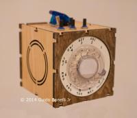
It’s called ORBIS: The Wooden Kinetic & Lighting Sculpture. It mounts to the wall and provides a focal point for the room – a bright flashy spinning one at that! Does it just stay there and do random things? Nope, of course not! [Guido] built it with a unique control box, two Arduino 2560’s and an Xbee to communicate between them.

Orbit Kinetic Sculpture

He was told to design it using old and new technologies so he’s got a rotary phone dial on the side of the box which allows the user to change through the different modes.

Switches on top also let you change the color of the sculpture and the speed at which it moves around. Since it’s wireless it can be easily set on the coffee table and become an instant conversation starter.

See it in action after the break.


Filed under: Arduino Hacks, laser hacks, led hacks


  • Newsletter

    Sign up for the PlanetArduino Newsletter, which delivers the most popular articles via e-mail to your inbox every week. Just fill in the information below and submit.

  • Like Us on Facebook