Posts | Comments

Planet Arduino

Archive for the ‘Texas Instruments’ Category

Oct
03

A sneak preview of Arduino TRE powered by Texas Instruments

Announcements, ArduinoTre, Linux, MakerFaire, Massimo Banzi, Sitara, Texas Instruments, TRE Comments Off on A sneak preview of Arduino TRE powered by Texas Instruments 

Arduino TRE

Next saturday  5th of October Massimo Banzi with Jason Kridner and Gerald Coley (Texas Instrument) will talk about the new collaboration on Arduino TRE during a talk at Maker Faire Rome ( from 15.30 in Room G – Archimede).

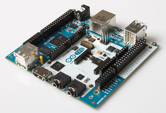
Arduino TRE, based on the Texas Instruments Sitara AM335x ARM Cortex-A8 processor is the “most powerful Arduino to date” and the first that will be able to run “full Linux.”

Thanks to the 1-GHz Sitara AM335x processor, Arduino developers get up to 100 times more performance with the Sitara-processor-based TRE than they do on the Arduino Leonardo or Uno. This performance opens the doors to more advanced Linux-powered applications. The Sitara-processor-based Linux Arduino can run high-performance desktop applications, processing-intensive algorithms or high-speed communications.

The Arduino TRE is two Arduinos in one: the Sitara-processor-based Linux Arduino plus a full AVR-based Arduino, while leveraging the simplicity of the Arduino software experience. The integration of the AVR Arduino enables the Arduino TRE to use the existing shield ecosystem so that innovators can expand the Arduino TRE to develop a wide range of high-performance applications such as 3D printers, gateways for building automation and lighting automation, telemetry hubs that collect data from nearby sensors wirelessly, and other connected applications that require host control plus real-time operations. 

In addition, the Arduino TRE is partially the result of a close collaboration between Arduino and the BeagleBoard.org foundation. These open hardware pioneers share a passion for expanding open source development and making technology accessible for artists, designers and hobbyists. The TRE design builds upon the experience of both Arduino and BeagleBoard, combining the benefits of both community based boards.

“By choosing TI’s Sitara AM335x processor to power the Arduino TRE, we’re enabling customers to leverage the capabilities of an exponentially faster processor running full Linux,” said Massimo Banzi, co-founder, Arduino.

“Our customers now have a scalable portfolio at their fingertips, from the microcontroller-based Uno to the TRE Linux computer.”

The Arduino TRE is expected to be available in spring 2014 but you’ll be able to see it live during Maker Faire Rome.

See more pictures of Arduino TRE on Flickr.

Hello readers

Today we are going to examine the Texas Instruments TLC5940 16-channel LED driver IC. My reason for doing this is to demonstrate another, easier way of driving many LEDs as well as LED display modules that are common-anode. If you have a common-cathode display module, you should have a look at the Maxim MAX7219. Moving along, here is the IC:

Another nice big DIP IC. Also available in HTSSOP and QFN packaging. What can this IC do for us? It can control 16 LEDs per IC, and also be cascaded to control more and more, with the display data arriving via a serial line in the same manner as a 74HC595 shift register. Furthermore, another benefit of this IC is that you don’t need matching current-limiting resistors for your LEDs, as this IC is a current sink, in that the current flows from the 5V rail, through the LED, then into the IC. However, it can control the brightness of the LEDs using pulse-width modulation over 4096 steps via software, or using a single resistor.

What is pulse-width modulation? Normally an LED might be on, or off. But if you switch it on and off very quickly, it does not look as bright (as it is not on 100% of the time). If you alter the period of time between on and off, you can alter the perceived brightness of the LED. Here is an example, compare the brightness of the LED bars against the display of the CRO – as the brightness increases, the voltage (amplitude [vertical thickness]) spreads across the entire time period (horizontal axis); as the brightness decreases, the voltage spread across time retreats:

Using the IC is very easy on the hardware front. Here is the data sheet: TLC5940.pdf. The pinout diagram is quite self-explanatory:

Pins OUT0~OUT15 are the current-sink pins for each LED. When one is selected they allow current to flow into the IC from the 5V rail, with the LED in between – turning it on. However it is easier to understand with a practical example, such as this (click to enlarge):

Here we have our Arduino board or compatible sending serial data to the TLC5940 to control sixteen LEDs. The 2k ohm resistor is required to set the maximum current available to flow through the LEDs, thereby adjusting their brightness. Using software you can adjust the brightness with PWM for each LED by itself. Very important: this circuit will need external power into the Arduino or a separate 5V power supply. The circuitry on the breadboard draws up to ~318 mA by itself – running the Arduino from USB only made it somewhat flaky in operation. Here is the circuit in action with an ammeter between the breadboard and 5V out on the Arduino:

Anyhow, let’s get moving once more – here is the assembled demonstration circuit:

For our example, we will be using the Arduino way of doing things. Thankfully (once more) there is a library to make controlling the IC exponentially easier. The library page and download files are available from here; the documentation page is here.  If you need guidance on installing a library, please visit here. However the commands to control the IC are quite simple with the Arduino library.

First of all, include the TLC5940 library, as such:

#include “Tlc5940.h”

Then in void setup(); you create the object using the function:

Tlc.init();

You can insert a number between 0 and 4095 to set the starting PWM (LED brightness) value, however this is optional.

Setting an output for display requires two functions, first Tlc.set(l, p); where l is the output (0~15) and p is the PWM brightness level – then execute Tlc.update(); which sends the command to the IC to be executed. The sketch below is easy to follow and understand the process involved.

Moving forward with the demonstration, here is the sketch  – TLC5940demo.pdf, and the video clip of operation:

When the LEDs are glowing from dim to bright and return, we are altering the PWM value of the LEDs to adjust their brightness. This also occurs during the last operation where the LEDs are operating like the bonnet of KITT.

Well once again that’s enough blinkiness for now, again this is another useful IC that helps simplify things and be creative. As always, avoid the risk of counterfeit ICs  – so please avoid disappointment, support your local teams and buy from a reputable distributor. Living in Australia, mine came from Farnell (part number 1226306). So have fun!

Remember, if you have any questions at all please leave a comment (below). We also have a Google Group dedicated to the projects and related items on the website – please sign up, it’s free and we can all learn something. High resolution photos are available from flickr.

Otherwise, have fun, stay safe, be good to each other – and make something! :)

[Note – the TLC5940 was purchased by myself personally and reviewed without notifying the manufacturer or retailer]


  • Newsletter

    Sign up for the PlanetArduino Newsletter, which delivers the most popular articles via e-mail to your inbox every week. Just fill in the information below and submit.

  • Like Us on Facebook