Posts | Comments

Planet Arduino

Archive for the ‘TI’ Category

Introduction

This is the second of three articles that will examine the LM391x series of LED driver ICs. The first covered the LM3914, this will cover the LM3915 and the LM3916 will follow. The goal of these is to have you using the parts in a small amount of time and experiment with your driver ICs, from which point you can research further into their theory and application.

Although these parts have been around for many years, the LM3915 isn’t used that much however for the sake of completeness we’re writing the tutorial. The LM3915 offers a simple way to display a logarithmic voltage level using one or more groups of ten LEDs with a minimum of fuss. If you’re wanting to make a VU meter, you should use the LM3916 which we will cover in the final instalment of this trilogy.

Instead of having each LED represent a voltage level as with the LM3914, each LED connected to the LM3915 represents a 3 dB (decibel) change in the power level of the signal. For more on decibels, check out Wikipedia.

To display these power level changes we’ll run through a couple of examples that you can use in your own projects and hopefully give you some ideas for the future. Originally by National Semiconductor, the LM391X series is now handled by Texas Instruments.

LM3915

Getting Started

You will need the LM3915 data sheet, so please download that and keep it as a reference. First – back to basics. The LM3915 controls ten LEDs. It controls the current through the LEDs with the use of only one resistor, and the LEDs can appear in a bar graph or single ‘dot’ when in use. The LM3915 contains a ten-stage voltage divider, each stage when reached will illuminate the matching LED (and those below it in level meter mode).

Let’s consider the most basic of examples (from page two of the data sheet) – a simple logarithmic display of voltage between 0 and 10V:

LM3915 demo board circuitAfter building the circuit you can connect a signal to measure via pin 5, and the GND to pin 2. We’ve built the circuit exactly as above on some stripboard for demonstration purposes, with the only difference being the use of an 8.2kΩ resistor for R2:

LM3915 demo board

To show this in action we use a signal of varying AC voltage – a sine wave at around 2 kHz. In the following video, you can see the comparison of the signal’s voltage against the LEDs being illuminated, and you will see the logarithmic voltage increase represented by the LEDs:

We used the bar display mode for the voltage increase, and the dot display mode for the voltage decrease. Did you notice that during the voltage decrease, the LEDs below the maximum level being displayed were dim? As the signal’s voltage was varying very quickly, the change in the LED’s location is a blur due to the speed of change. In the video below, we’ve slowed the frequency right down but kept the same maximum voltage.

Well that was a lot of fun, and gives you an idea of what is possible with the LM3915.

Displaying weaker signals

In non-theoretical situations your input signal won’t conveniently be between 0 and 10 V. For example the line level on audio equipment can vary between 1 and 3V peak to peak. For example, here’s a random DSO image from measuring the headphone output on my computer whilst playing some typical music:

audio signal LM3915 PC sound

Although it’s an AC signal we’ll treat it as DC for simplicity. So to display this random low DC voltage signal we’ll reduce the range of the display to 0~3V DC. This is done using  the same method as with the LM3914 – with maths and different resistors.

Consider the following formulae:

LM3915 reference voltage formula

As you can see the LED current (Iled) is simple, however we’ll need to solve for R1 and R2 with the first formula to get our required Vref of 3V. For our example circuit I use 2.2kΩ for R2 which gives a value of 1.8kΩ for R1. However putting those values in the ILED formula gives a pretty low current for the LEDs, about 8.3 mA. Live and learn – so spend time experimenting with values so you can match the required Vref and ILED.

Nevertheless in this video below we have the Vref of 3V and some music in from the computer as a sample source of low-voltage DC. This is not a VU meter! Wait for the LM3916 article to do that.

Again due to the rapid rate of change of the voltage, there is the blue between the maximum level at the time and 0V.

Chaining multiple LM3915s

This is covered well in the data sheet, so read it for more on using two LM3915s. Plus there are some great example circuits in the data sheet, for example the 100W audio power meter on page 26 and the vibration meter (using a piezo) on page 18.

Conclusion

As always I hope you found this useful. Don’t forget to stay tuned for the final instalment about the LM3916. And if you made it this far – check out my new book “Arduino Workshop” from No Starch Press.

In the meanwhile have fun and keep checking into tronixstuff.com. Why not follow things on twitterGoogle+, subscribe  for email updates or RSS using the links on the right-hand column? And join our friendly Google Group – dedicated to the projects and related items on this website. Sign up – it’s free, helpful to each other –  and we can all learn something.

Oct
21

Tutorial – Arduino and the TLC5940 PWM LED Driver IC

anode, arduino, BOB-10616, COM-10136, common, guide, instruments, LED, PWM, servo, texas, TI, TLC5940, tronixstuff, tutorial Comments Off on Tutorial – Arduino and the TLC5940 PWM LED Driver IC 

Use the Texas Instruments TLC5940 16-Channel LED Driver IC with Arduino in Chapter 57 of our Arduino Tutorials. The first chapter is here, the complete series is detailed here.

Introduction

Today we are going to examine the Texas Instruments TLC5940 16-channel LED driver IC. Our reason for doing this is to demonstrate another, easier way of driving many LEDs – and also servos.  First up, here is a few examples of the TLC5940

TLC5940

The TLC5940 is available in the DIP version above, and also surface-mount. It really is a convenient part, allowing you to adjust the brightness of sixteen individual LEDs via PWM (pulse-width modulation) – and you can also daisy-chain more than one TLC5940 to control even more.

During this tutorial we’ll explain how to control one or more TLC5940 ICs with LEDs and also look at controlling servos. At this point, please download a copy of the TLC5940_data_sheet (.pdf) as you will refer to it through this process. Furthermore, please download and install the TLC5940 Arduino library by Alex Leone which can be found here. If you’re not sure how to install a library, click here.

Build a TLC5940 demonstration circuit

The following circuit is the minimum required to control sixteen LEDs from your Arduino or compatible. You can use it to experiment with various functions and get an idea of what is possible. You will need:

  • An Arduino Uno or compatible board
  • 16 normal, everyday LEDs that can have a forward current of up to 20 mA
  • a 2 kΩ resistor (give or take 10%)
  • a 0.1uF ceramic and a 4.7uF electrolytic capacitor

Take note of the LED orientation – and remember the TLC5940 is a common-anode LED driver – so all the LED anodes are connected together and then to 5V:

TLC5940 Arduino circuit

For this particular circuit, you won’t need an external 5V power supply – however you may need one in the future. The purpose of the resistor is to control the amount of current that can flow through the LEDs. The required resistor value is calculated with the following formula:

R = 39.06 / Imax

where R (in Ohms)  is the resistor value and Imax (in Amps) is the maximum amount of current you want to flow through the LEDs. For example, if you have LEDs with a 20 mA forward current – the resistor calculation would be:

R = 39.06 / 0.02 = 1803 Ohms.

Once you have the circuit assembled – open up the Arduino IDE and upload the sketch BasicUse.pde  which is in the example folder for the TLC5940 library. You should be presented with output similar to what is shown in the following video:

Controlling the TLC5940

Now that the circuit works, how do we control the TLC5940? First, the mandatory functions – include the library at the start of the sketch with:

#include "Tlc5940.h"

and then initialise the library by placing the following into void setup():

Tlc.init(x);

x is an optional parameter – if you want to set all the channels to a certain brightness as soon as the sketch starts, you can insert a value between 0 and 4095 for in the Tlc.init() function.

Now to turn a channel/LED on or off. Each channel is numbered from 0 to 15, and each channel’s brightness can be adjusted between 0 and 4095.

This is a two-part process…

First – use one or more of the following functions to set up the required channels and respective brightness (PWM level):

Tlc.set(channel, brightness);

For example, if you wanted to have the first three channels on at full brightness, use:

Tlc.set(0, 4095);
Tlc.set(1, 4095);
Tlc.set(2, 4095);

The second part is to use the following to update the TLC5940 with the required instructions from part one:

Tlc.update();

If you want to turn off all channels at once, simply use:

Tlc.clear();

You don’t need to call a TLC.update() after the clear function. The following is a quick example sketch that sets the brightness/PWM values of all the channels to different levels:

#include "Tlc5940.h"
void setup()
{
  Tlc.init(0); // initialise TLC5940 and set all channels off
}

void loop()
{
  for (int i = 0; i < 16; i++)
  {
    Tlc.set(i, 1023);
  }
  Tlc.update();
  delay(1000);
  for (int i = 0; i < 16; i++)
  {
    Tlc.set(i, 2046);
  }
  Tlc.update();
  delay(1000);
  for (int i = 0; i < 16; i++)
  {
    Tlc.set(i, 3069);
  }
  Tlc.update();
  delay(1000);
  for (int i = 0; i < 16; i++)
  {
    Tlc.set(i, 4095);
  }
  Tlc.update();
  delay(1000);
}

and the sketch in action:

The ability to control individual brightness for each channel/LED can also be useful when controlling RGB LEDs – you can then easily select required colours via different brightness levels for each element.

Using two or more TLC5940s

You can daisy-chain quite a few TLC5940s together to control more LEDs. First – wire up the next TLC5940 to the Arduino as shown in the demonstration circuit – except connect the SOUT pin (17) of the first TLC5940 to the SIN pin (26) of the second TLC5940 – as the data travels from the Arduino, through the first TLC5940 to the second and so on. Then repeat the process if you have a third, etc. Don’t forget the resisotr that sets the current!

Next, open the file tlc_config.h located in the TLC5940 library folder. Change the value of NUM_TLCS to the number of TLC5940s you have connected together, then save the file and also delete the file Tlc5940.o also located in the same folder. Finally restart the IDE. You can then refer to the channels of the second and further TLC5940 sequentially from the first. That is, the first is 0~15, the second is 16~29, and so on.

Controlling servos with the TLC5940

As the TLC5940 generates PWM (pulse-width modulation) output, it’s great for driving servos as well. Just like LEDs – you can control up to sixteen at once. Ideal for creating spider-like robots, strange clocks or making some noise. When choosing your servo, ensure that it doesn’t draw more than 120 mA when operating (the maximum current per channel) and also heed the “Managing current and heat” section at the end of this tutorial. And use external power with servos, don’t rely on the Arduino’s 5V line.

To connect a servo is simple – the GND line connects to GND, the 5V (or supply voltage lead) connects to your 5v (or other suitable supply) and the servo control pin connects to one of the TLC5940′s outputs. Finally – and this is important – connect a 2.2kΩ resistor between the TLC5940 output pin(s) being used and 5V.

Controlling a servo isn’t that different to an LED. You need the first two lines at the start of the sketch:

#include "Tlc5940.h"
#include "tlc_servos.h"

then the following in void setup():

tlc_initServos();

Next, use the following function to select which servo (channel) to operate and the required angle (angle):

tlc_setServo(channel, angle);

Just like the LEDs you can bunch a few of these together, and then execute the command with:

Tlc.update();

So let’s see all that in action. The following example sketch sweeps four servos across 90 degrees:

#include "Tlc5940.h"
#include "tlc_servos.h"

void setup()
{
  tlc_initServos();  // Note: this will drop the PWM freqency down to 50Hz.
}

void loop()
{
  for (int angle = 0; angle < 90; angle++) {
    tlc_setServo(0, angle);
    tlc_setServo(1, angle);
    tlc_setServo(2, angle);
    tlc_setServo(3, angle);    
    Tlc.update();
    delay(5);
  }
  for (int angle = 90; angle >= 0; angle--) {
    tlc_setServo(0, angle);
    tlc_setServo(1, angle);
    tlc_setServo(2, angle);
    tlc_setServo(3, angle);    
    Tlc.update();
    delay(5);
  }
}

And the following video captures those four servos in action:


If you servos are not rotating to the correct angle – for example you ask for 180 degrees and they only rotate to 90 or thereabouts, a little extra work is required. You need to open the tlc_servos.h file located in the TLC5940 Arduino library folder and experiment with the values for SERVO_MIN_WIDTH and SERVO_MAX_WIDTH. For example change SERVO_MIN_WIDTH from 200 to 203 and SERVO_MAX_WIDTH from 400 to 560.

Managing current and heat 

As mentioned earlier, the TLC5940 can handle a maximum of 120 mA per channel. After some experimenting you may notice that the TLC5940 does get warm – and that’s ok. However there is a maximum limit to the amount of power that can be dissipated before destroying the part. If you are just using normal garden-variety LEDs or smaller servos, power won’t be a problem. However if you’re planning on using the TLC5940 to the max – please review the notes provided by the library authors.

Conclusion

Once again you’re on your way to controlling an incredibly useful part with your Arduino. Now with some imagination you can create all sorts of visual displays or have fun with many servos. And if you enjoyed the tutorial, or want to introduce someone else to the interesting world of Arduino – check out my book (now in a third printing!) “Arduino Workshop” from No Starch Press.

tronixstuff

In the meanwhile have fun and keep checking into tronixstuff.com. Why not follow things on twitterGoogle+, subscribe  for email updates or RSS using the links on the right-hand column? And join our friendly Google Group – dedicated to the projects and related items on this website. Sign up – it’s free, helpful to each other –  and we can all learn something.

The post Tutorial – Arduino and the TLC5940 PWM LED Driver IC appeared first on tronixstuff.

Oct
21

Tutorial – Arduino and the TLC5940 PWM LED Driver IC

anode, arduino, BOB-10616, COM-10136, common, guide, instruments, LED, multiple, PWM, servo, texas, TI, TLC5940, tronixstuff, tutorial Comments Off on Tutorial – Arduino and the TLC5940 PWM LED Driver IC 

Use the Texas Instruments TLC5940 16-Channel LED Driver IC with Arduino in Chapter 57 of our Arduino Tutorials. The first chapter is here, the complete series is detailed here.

Introduction

Today we are going to examine the Texas Instruments TLC5940 16-channel LED driver IC. Our reason for doing this is to demonstrate another, easier way of driving many LEDs – and also servos.  First up, here is a few examples of the TLC5940

TLC5940

The TLC5940 is available in the DIP version above, and also surface-mount. It really is a convenient part, allowing you to adjust the brightness of sixteen individual LEDs via PWM (pulse-width modulation) – and you can also daisy-chain more than one TLC5940 to control even more.

During this tutorial we’ll explain how to control one or more TLC5940 ICs with LEDs and also look at controlling servos. At this point, please download a copy of the TLC5940_data_sheet (.pdf) as you will refer to it through this process. Furthermore, please download and install the TLC5940 Arduino library by Alex Leone which can be found here. If you’re not sure how to install a library, click here.

Build a TLC5940 demonstration circuit

The following circuit is the minimum required to control sixteen LEDs from your Arduino or compatible. You can use it to experiment with various functions and get an idea of what is possible. You will need:

  • An Arduino Uno or compatible board
  • 16 normal, everyday LEDs that can have a forward current of up to 20 mA
  • a 2 kΩ resistor (give or take 10%)
  • a 0.1uF ceramic and a 4.7uF electrolytic capacitor

Take note of the LED orientation – and remember the TLC5940 is a common-anode LED driver – so all the LED anodes are connected together and then to 5V:

TLC5940 Arduino circuit

For this particular circuit, you won’t need an external 5V power supply – however you may need one in the future. The purpose of the resistor is to control the amount of current that can flow through the LEDs. The required resistor value is calculated with the following formula:

R = 39.06 / Imax

where R (in Ohms)  is the resistor value and Imax (in Amps) is the maximum amount of current you want to flow through the LEDs. For example, if you have LEDs with a 20 mA forward current – the resistor calculation would be:

R = 39.06 / 0.02 = 1803 Ohms.

Once you have the circuit assembled – open up the Arduino IDE and upload the sketch BasicUse.pde  which is in the example folder for the TLC5940 library. You should be presented with output similar to what is shown in the following video:

Controlling the TLC5940

Now that the circuit works, how do we control the TLC5940? First, the mandatory functions – include the library at the start of the sketch with:

#include "Tlc5940.h"

and then initialise the library by placing the following into void setup():

Tlc.init(x);

x is an optional parameter – if you want to set all the channels to a certain brightness as soon as the sketch starts, you can insert a value between 0 and 4095 for in the Tlc.init() function.

Now to turn a channel/LED on or off. Each channel is numbered from 0 to 15, and each channel’s brightness can be adjusted between 0 and 4095.

This is a two-part process…

First – use one or more of the following functions to set up the required channels and respective brightness (PWM level):

Tlc.set(channel, brightness);

For example, if you wanted to have the first three channels on at full brightness, use:

Tlc.set(0, 4095);
Tlc.set(1, 4095);
Tlc.set(2, 4095);

The second part is to use the following to update the TLC5940 with the required instructions from part one:

Tlc.update();

If you want to turn off all channels at once, simply use:

Tlc.clear();

You don’t need to call a TLC.update() after the clear function. The following is a quick example sketch that sets the brightness/PWM values of all the channels to different levels:

#include "Tlc5940.h"
void setup()
{
  Tlc.init(0); // initialise TLC5940 and set all channels off
}

void loop()
{
  for (int i = 0; i < 16; i++)
  {
    Tlc.set(i, 1023);
  }
  Tlc.update();
  delay(1000);
  for (int i = 0; i < 16; i++)
  {
    Tlc.set(i, 2046);
  }
  Tlc.update();
  delay(1000);
  for (int i = 0; i < 16; i++)
  {
    Tlc.set(i, 3069);
  }
  Tlc.update();
  delay(1000);
  for (int i = 0; i < 16; i++)
  {
    Tlc.set(i, 4095);
  }
  Tlc.update();
  delay(1000);
}

and the sketch in action:

The ability to control individual brightness for each channel/LED can also be useful when controlling RGB LEDs – you can then easily select required colours via different brightness levels for each element.

Using two or more TLC5940s

You can daisy-chain quite a few TLC5940s together to control more LEDs. First – wire up the next TLC5940 to the Arduino as shown in the demonstration circuit – except connect the SOUT pin (17) of the first TLC5940 to the SIN pin (26) of the second TLC5940 – as the data travels from the Arduino, through the first TLC5940 to the second and so on. Then repeat the process if you have a third, etc. Don’t forget the resisotr that sets the current!

Next, open the file tlc_config.h located in the TLC5940 library folder. Change the value of NUM_TLCS to the number of TLC5940s you have connected together, then save the file and also delete the file Tlc5940.o also located in the same folder. Finally restart the IDE. You can then refer to the channels of the second and further TLC5940 sequentially from the first. That is, the first is 0~15, the second is 16~29, and so on.

Controlling servos with the TLC5940

As the TLC5940 generates PWM (pulse-width modulation) output, it’s great for driving servos as well. Just like LEDs – you can control up to sixteen at once. Ideal for creating spider-like robots, strange clocks or making some noise. When choosing your servo, ensure that it doesn’t draw more than 120 mA when operating (the maximum current per channel) and also heed the “Managing current and heat” section at the end of this tutorial. And use external power with servos, don’t rely on the Arduino’s 5V line.

To connect a servo is simple – the GND line connects to GND, the 5V (or supply voltage lead) connects to your 5v (or other suitable supply) and the servo control pin connects to one of the TLC5940′s outputs. Finally – and this is important – connect a 2.2kΩ resistor between the TLC5940 output pin(s) being used and 5V.

Controlling a servo isn’t that different to an LED. You need the first two lines at the start of the sketch:

#include "Tlc5940.h"
#include "tlc_servos.h"

then the following in void setup():

tlc_initServos();

Next, use the following function to select which servo (channel) to operate and the required angle (angle):

tlc_setServo(channel, angle);

Just like the LEDs you can bunch a few of these together, and then execute the command with:

Tlc.update();

So let’s see all that in action. The following example sketch sweeps four servos across 90 degrees:

#include "Tlc5940.h"
#include "tlc_servos.h"

void setup()
{
  tlc_initServos();  // Note: this will drop the PWM freqency down to 50Hz.
}

void loop()
{
  for (int angle = 0; angle < 90; angle++) {
    tlc_setServo(0, angle);
    tlc_setServo(1, angle);
    tlc_setServo(2, angle);
    tlc_setServo(3, angle);    
    Tlc.update();
    delay(5);
  }
  for (int angle = 90; angle >= 0; angle--) {
    tlc_setServo(0, angle);
    tlc_setServo(1, angle);
    tlc_setServo(2, angle);
    tlc_setServo(3, angle);    
    Tlc.update();
    delay(5);
  }
}

And the following video captures those four servos in action:


If you servos are not rotating to the correct angle – for example you ask for 180 degrees and they only rotate to 90 or thereabouts, a little extra work is required. You need to open the tlc_servos.h file located in the TLC5940 Arduino library folder and experiment with the values for SERVO_MIN_WIDTH and SERVO_MAX_WIDTH. For example change SERVO_MIN_WIDTH from 200 to 203 and SERVO_MAX_WIDTH from 400 to 560.

Managing current and heat 

As mentioned earlier, the TLC5940 can handle a maximum of 120 mA per channel. After some experimenting you may notice that the TLC5940 does get warm – and that’s ok. However there is a maximum limit to the amount of power that can be dissipated before destroying the part. If you are just using normal garden-variety LEDs or smaller servos, power won’t be a problem. However if you’re planning on using the TLC5940 to the max – please review the notes provided by the library authors.

Conclusion

Once again you’re on your way to controlling an incredibly useful part with your Arduino. Now with some imagination you can create all sorts of visual displays or have fun with many servos. And if you enjoyed the tutorial, or want to introduce someone else to the interesting world of Arduino – check out my book (now in a third printing!) “Arduino Workshop” from No Starch Press.

tronixstuff

In the meanwhile have fun and keep checking into tronixstuff.com. Why not follow things on twitterGoogle+, subscribe  for email updates or RSS using the links on the right-hand column? And join our friendly Google Group – dedicated to the projects and related items on this website. Sign up – it’s free, helpful to each other –  and we can all learn something.

The post Tutorial – Arduino and the TLC5940 PWM LED Driver IC appeared first on tronixstuff.

Oct
03

Talking to Jason Kridner About the new Arduino Tre

arduino, Arduino Tre, beagleboard, BeagleBone, CircuitCo, Electronics, TI, TRE, xBee, Yun Comments Off on Talking to Jason Kridner About the new Arduino Tre 

Top view of the new Arduino Tre board.With information about the new Arduino Tre board scare on the ground, I managed to track down Jason Kridner from the BeagleBoard Foundation to talk about the new board.

Read more on MAKE

Oct
03

First Look at the New Arduino Tre

arduino, Arduino Tre, beagleboard, Electronics, TI Comments Off on First Look at the New Arduino Tre 

Near-side of the board: USB (left), HDMI (middle) and Audio In/Out (right). Far-side of the board: 5V power jack (left), micro-USB (lift-middle), Ethernet (right-middle) and USB (right).As Maker Faire Rome kicked off earlier today Arduino announced two new boards: the Galileo in collaboration with Intel, and the Tre in collaboration with Texas Instruments and the BeagleBoard Foundation.

Read more on MAKE

Sep
13

Tutorial – LM3914 Dot/Bar Display Driver IC

bar, display, dot, driver, Electronics, example, IC, LED, level, LM3914, LM3915, LM3916, TI, tronixstuff, tutorial, voltmeter Comments Off on Tutorial – LM3914 Dot/Bar Display Driver IC 

Introduction

This is the first of three tutorials that will examine the LM391x series of LED driver ICs. In this first tutorial we cover the LM3914, then the LM3915 and LM3916 will follow. The goal of these tutorials is to have you using the parts in a small amount of time and experiment with your driver ICs, from which point you can research further into their theory and application.

Although these parts have been around for many years, the LM3914 in particular is still quite popular. It offers a simple way to display a linear voltage level using one or more groups of ten LEDs with a minimum of fuss.

With a variety of external parts or circuitry these LEDs can then represent all sorts of data, or just blink for your amusement. We’ll run through a few example circuits that you can use in your own projects and hopefully give you some ideas for the future. Originally by National Semiconductor, the LM391X series is now handled by Texas Instruments.

LM3914

Getting Started

You will need the LM3914 data sheet, so please download that and keep it as a reference. So – back to basics. The LM3914 controls ten LEDs. It controls the current through the LEDs with the use of only one resistor, and the LEDs can appear in a bar graph or single ‘dot’ when in use. The LM3914 contains a ten-stage voltage divider, each stage when reached will illuminate the matching LED (and those below it in level meter mode).

Let’s consider the most basic of examples (from page two of the data sheet) – a voltmeter with a range of 0~5V:

 LM3914 5V voltmeter circuit

The Vled rail is also connected to the supply voltage in our example. Pin 9 controls the bar/dot display mode – with it connected to pin 3 the LEDs will operate in bar graph mode, leave it open for dot mode. The 2.2uF capacitor is required only when “leads to the LED supply are 6″ or longer”. We’ve hooked up the circuit above, and created a 0~5V DC source via a 10kΩ potentiometer with a multimeter to show the voltage – in the following video you can see the results of this circuit in action, in both dot and bar graph mode:

Customising the upper range and LED current

Well that was exciting, however what if you want a different reference voltage? That is you want your display to have a range of 0~3 V DC? And how do you control the current flow through each LED? With maths and resistors. Consider the following formulae:

LM3914 formulae

As you can see the LED current (Iled) is simple, our example is 12.5/1210 which returned 10.3 mA – and in real life 12.7 mA (resistor tolerance is going to affect the value of the calculations).

Now to calculate a new Ref Out voltage – for example  we’ll shoot for a 3 V meter, and keep the same current for the LEDs. This requires solving for R2 in the equation above, which results with R2 = -R1 + 0.8R1V. Substituting the values – R2 = -1210 + 0.8 x 1210 x 3 gives a value of 1694Ω for R2. Not everyone will have the E48 resistor range, so try and get something as close as possible. We found a 1.8 kΩ for R2 and show the results in the following video:

You can of course have larger display range values, but a supply voltage of no more than 25 V will need to be equal to or greater than that value. E.g. if you want a 0~10 V display, the supply voltage must be >= 10V DC.

Creating custom ranges

Now we’ll look at how to create  a lower range limit, so you can have displays that (for example) can range from a non-zero positive value. For example, you want to display levels between 3 and 5V DC. From the previous section, you know how to set the upper limit, and setting the lower limit is simple – just apply the lower voltage to pin 4 (Rlo).

You can derive this using a resistor divider or other form of supply with a common GND. When creating such circuits, remember that the tolerance of the resistors used in the voltage dividers will have an affect on the accuracy. Some may wish to fit trimpots, which after alignment can be set permanently with a blob of glue.

Finally, for more reading on this topic – download and review the TI application note.

Chaining multiple LM3914s

Two or more LM3914s can be chained together to increase the number of LEDs used to display the levels over an expanded range. The circuitry is similar to using two independent units, except the REFout (pin 7) from the first LM3914 is fed to the REFlo (pin 4) of the second LM3914 – whose REFout is set as required for the upper range limit. Consider the following example schematic which gave a real-world range of 0~3.8V DC:

LM3914

The 20~22kΩ resistor is required if you’re using dot mode (see “Dot mode carry” in page ten of the data sheet). Moving on, the circuit above results with the following:

Where to from here?

Now you can visually represent all sorts of low voltages for many purposes. There’s more example circuits and notes in the LM3914 data sheet, so have a read through and delve deeper into the operation of the LM3914. Furthermore Dave Jones from eevblog.com has made a great video whcih describes a practical application of the LM3914:

Conclusion

As always I hope you found this useful. Don’t forget to stay tuned for the second and third instalments using the LM3915 and LM3916. Full-sized images are on flickr. And if you made it this far – check out my new book “Arduino Workshop” from No Starch Press.

In the meanwhile have fun and keep checking into tronixstuff.com. Why not follow things on twitterGoogle+, subscribe  for email updates or RSS using the links on the right-hand column? And join our friendly Google Group – dedicated to the projects and related items on this website. Sign up – it’s free, helpful to each other –  and we can all learn something.

The post Tutorial – LM3914 Dot/Bar Display Driver IC appeared first on tronixstuff.

Introduction

Every month Australian electronics magazine Silicon Chip publishes a variety of projects, and in March 2004  they published the “DC-DC converter” project. Altronics picked it up and now offers a kit, the subject of our review. The main purpose of this converter kit is to allow replacement of expensive PP3 9V batteries with 2 AA cells, to enable a cheaper and longer lifespan over use. With a slight modification it can also act as a trickle-charger for 2 rechargeable AA cells (that can then supply power to the converter) via a plugpack. And there’s some educational value if you’re so inclined, as you can learn about voltage converters as well.

Assembly

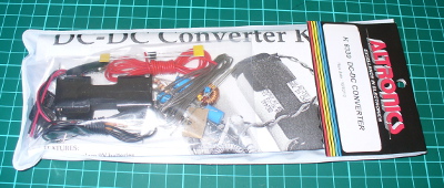
As usual for Altronics the kit is in a typical retail package:

packaged

…which includes the detailed instructions (based on the original Silicon Chip article), a handy reference guide and of course the parts:

contents

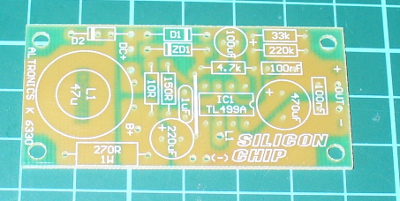
The PCB has a good silk screen and solder mask:

pcbtop

pcbbottom

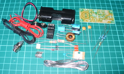
and all the required parts are included:

components

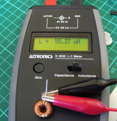
It was nice to see plenty of extra black and red wire for modifications or final installations, the battery snap, 2 x AA cell holder and a DC socket for use with the optional plug pack mentioned earlier. That hand-wound inductor was interesting, and I couldn’t help but measure it on the LC meter:

lcmeter

It was supposed to be a 47 uH inductor, so let’s hope that doesn’t cause too much trouble. Assembly was quite straight-forward – just start with the smallest components first and build up. If you’re not going to have the trickle-charge function, heed the notes in the manual and don’t install D2 or R4. The only fiddly bit was the “short as possible” (red) link across the board:

longlink

And after a few more minutes it was finished. The external connections will vary depending on your application – however for the review I’ve got the 9V snap on the input, which makes it easy to connect the 2 AA cell holder to power the converter. Nice to see the holes around the perimeter of the board, which make mounting it more permanently quite easy.

Operation

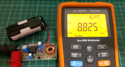
After a bench clean-up it was time to connect 2 AA rechargeable cells and see what we can get out of the converter. The cells measured 2.77V together before connection, and without a load on the converter the resulting output was 8.825 V:

firsttest

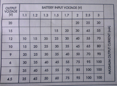
We can live with that. Furthermore the quiescent current (a situation with the power connected and not having a load on the output) was 2.5 mA. Thus it would be a good idea to have a power switch in a real-world environment. Speaking of the real world (!) how much current can you get out of the converter? Generally PP3 battery applications are low current, as the battery itself isn’t good for that much – even an expensive “Energizer Ultimate Lithium” offers only 800 mAh (for $16). So using higher-capacity rechargeable AA cells and this kit will save money.  A table is included with the instructions that shows the possible uses:

tableofuse

According to the table my 2.77V supply should be good for ~80 mA. With some resistors in parallel we made a dummy load of 69 mA and measured 0.37A current draw from the AA cells. Thus the key to this kit – you find a cheaper or more plentiful power supply at a lower voltage to save you the expense of providing the higher voltage.

For example, if you had a pair of Sanyo Eneloop rechargeable AA cells (total 2.4 V at 2 Ah) they would give you around 5.4 hours of life (ignoring the fall-off of voltage towards the end of their charge life – however the eneloops are pretty good in that regard). Whereas a disposable PP3 mentioned earlier would offer around 2.1 hours (at $16) or a rechargeable unit (which offers 8.4 V at 175 mAh) would only last around 25 minutes. Note that you can change two resistors in the circuit to alter the output voltage, and the values have been listed in the instructions for outputs up to 15 V.

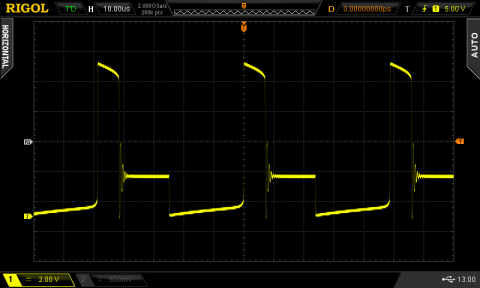
Finally, let’s consider the output waveforms from the circuit. With the aforementioned load, here’s the output on the DSO (click image to enlarge):

output

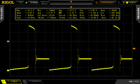
… and for interest’s sake, the switching output from the TL499 (click images to enlarge):

switchoutput

switchoutputdata

Conclusion

Apart from the described voltage-boosting functions this kit gives the interested builder experience with boost circuits and also the knowledge to create their own versions based on the original design, at a much lower cost than using other boost ICs . If you wanted a permanent certain voltage output, it would be better to breadboard the kit and experiment with the required resistors – then assemble the kit with the new values. And there is money and effort to be saved when subsituting with PP3 batteries. Finally, learning is a good thing!

So – a lot of fun and education for under $20. Purchase it from Altronics and their resellers, or read more about it in the September 2007 edition of Silicon Chip.

Full-sized images available on flickr. This kit was purchased without notifying the supplier.

And if you made it this far – check out my new book “Arduino Workshop” from No Starch Press.

In the meanwhile have fun and keep checking into tronixstuff.com. Why not follow things on twitterGoogle+, subscribe  for email updates or RSS using the links on the right-hand column? And join our friendly Google Group – dedicated to the projects and related items on this website. Sign up – it’s free, helpful to each other –  and we can all learn something.


Introduction

Every month Australian electronics magazine Silicon Chip publishes a variety of projects, and in March 2004  they published the “DC-DC converter” project. Altronics picked it up and now offers a kit, the subject of our review. The main purpose of this converter kit is to allow replacement of expensive PP3 9V batteries with 2 AA cells, to enable a cheaper and longer lifespan over use. With a slight modification it can also act as a trickle-charger for 2 rechargeable AA cells (that can then supply power to the converter) via a plugpack. And there’s some educational value if you’re so inclined, as you can learn about voltage converters as well.

Assembly

As usual for Altronics the kit is in a typical retail package:

packaged

…which includes the detailed instructions (based on the original Silicon Chip article), a handy reference guide and of course the parts:

contents

The PCB has a good silk screen and solder mask:

pcbtop

pcbbottom

and all the required parts are included:

components

It was nice to see plenty of extra black and red wire for modifications or final installations, the battery snap, 2 x AA cell holder and a DC socket for use with the optional plug pack mentioned earlier. That hand-wound inductor was interesting, and I couldn’t help but measure it on the LC meter:

lcmeter

It was supposed to be a 47 uH inductor, so let’s hope that doesn’t cause too much trouble. Assembly was quite straight-forward – just start with the smallest components first and build up. If you’re not going to have the trickle-charge function, heed the notes in the manual and don’t install D2 or R4. The only fiddly bit was the “short as possible” (red) link across the board:

longlink

And after a few more minutes it was finished. The external connections will vary depending on your application – however for the review I’ve got the 9V snap on the input, which makes it easy to connect the 2 AA cell holder to power the converter. Nice to see the holes around the perimeter of the board, which make mounting it more permanently quite easy.

Operation

After a bench clean-up it was time to connect 2 AA rechargeable cells and see what we can get out of the converter. The cells measured 2.77V together before connection, and without a load on the converter the resulting output was 8.825 V:

firsttest

We can live with that. Furthermore the quiescent current (a situation with the power connected and not having a load on the output) was 2.5 mA. Thus it would be a good idea to have a power switch in a real-world environment. Speaking of the real world (!) how much current can you get out of the converter? Generally PP3 battery applications are low current, as the battery itself isn’t good for that much – even an expensive “Energizer Ultimate Lithium” offers only 800 mAh (for $16). So using higher-capacity rechargeable AA cells and this kit will save money.  A table is included with the instructions that shows the possible uses:

tableofuse

According to the table my 2.77V supply should be good for ~80 mA. With some resistors in parallel we made a dummy load of 69 mA and measured 0.37A current draw from the AA cells. Thus the key to this kit – you find a cheaper or more plentiful power supply at a lower voltage to save you the expense of providing the higher voltage.

For example, if you had a pair of Sanyo Eneloop rechargeable AA cells (total 2.4 V at 2 Ah) they would give you around 5.4 hours of life (ignoring the fall-off of voltage towards the end of their charge life – however the eneloops are pretty good in that regard). Whereas a disposable PP3 mentioned earlier would offer around 2.1 hours (at $16) or a rechargeable unit (which offers 8.4 V at 175 mAh) would only last around 25 minutes. Note that you can change two resistors in the circuit to alter the output voltage, and the values have been listed in the instructions for outputs up to 15 V.

Finally, let’s consider the output waveforms from the circuit. With the aforementioned load, here’s the output on the DSO:

output

… and for interest’s sake, the switching output from the TL499:

switchoutput

switchoutputdata

Conclusion

Apart from the described voltage-boosting functions this kit gives the interested builder experience with boost circuits and also the knowledge to create their own versions based on the original design, at a much lower cost than using other boost ICs . If you wanted a permanent certain voltage output, it would be better to breadboard the kit and experiment with the required resistors – then assemble the kit with the new values. And there is money and effort to be saved when subsituting with PP3 batteries. Finally, learning is a good thing!

So – a lot of fun and education for under $20. Purchase it from Altronics and their resellers, or read more about it in the September 2007 edition of Silicon Chip.

Full-sized images available on flickr. This kit was purchased without notifying the supplier.

And if you made it this far – check out my new book “Arduino Workshop” from No Starch Press.

LEDborder

In the meanwhile have fun and keep checking into tronixstuff.com. Why not follow things on twitterGoogle+, subscribe  for email updates or RSS using the links on the right-hand column? And join our friendly Google Group – dedicated to the projects and related items on this website. Sign up – it’s free, helpful to each other –  and we can all learn something.

The post Kit review – Altronics/Silicon Chip DC to DC Converter appeared first on tronixstuff.

Jul
02

Tutorial – Arduino and the TI ADS1110 16-bit ADC

ADC, ads1110, analogue, arduino, converter, digital, i2c, instruments, texas, TI, tronixstuff, tutorial Comments Off on Tutorial – Arduino and the TI ADS1110 16-bit ADC 

Learn how to use the TI ADS1110 16-bit ADC with Arduino in chapter fifty-three of my Arduino Tutorials. The first chapter is here, the complete series is detailed here.

Updated 02/07/2013

Introduction

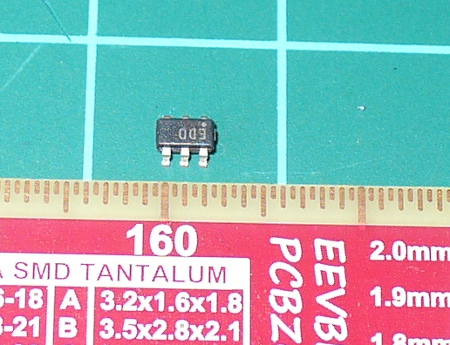
Moving on from the last chapter where we explained an 8-bit ADC, in this instalment we have the Texas Instruments ADS1110 – an incredibly tiny but useful 16-bit analogue-to-digital converter IC.  It can operate between 2.7 and 5.5 V so it’s also fine for Arduino Due and other lower-voltage development boards. This is a quick guide to get you going with the ADS1110 ready for further applications. Before continuing any further, please download the data sheet (pdf) as it will be useful and referred to during this tutorial. The ADS1110 gives you the option of a more accurate ADC than offered by the Arduino’s 10-bit ADCs – and it’s relatively easy to use. The only block for some is the package type – it’s only available in SOT23-6:

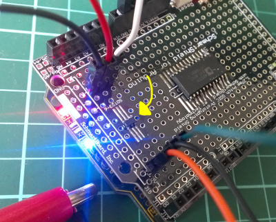
So unless you’re making a customised PCB, some sort of breakout will be required. One useful example is the Schmartboard we reviewed earlier:

ads1110schmartboard

The ADS1110 uses the I2C bus for communication, so if this is new to you – please review the I2C tutorials before continuing. And as there’s only six pins you can’t set the bus address – instead, you can select from six variants of the ADS1110 – each with their own address (see page two of the data sheet). As you can see the in the photo above, ours is marked “EDO” which matches to the bus address 1001000 or 0x48h. And with the example circuits we’ve used 10kΩ pull-up resistors on the I2C bus. You can use the ADS1110 as either a single-ended or differential ADC –  But first we need to examine the configuration register which is used to control various attributes, and the data register.

Configuration register

Turn to page eleven of the data sheet. The configuration register is one byte in size, and as the ADS1110 resets on a power-cycle – you need to reset the register if your needs are different to the defaults. The data sheet spells it out quite neatly… bits 0 and 1 determine the gain setting for the PGA (programmable gain amplifier). If you’re just measuring voltages or experimenting, leave these as zero for a gain of 1V/V. Next, the data rate for the ADS1110 is controlled with bits 2 and 3. If you have continuous sampling turned on, this determines the number of samples per second taken by the ADC.

After some experimenting with an Arduino Uno we found the values returned from the ADC were a bit off when using the fastest rate, so leave it as 15 SPS unless required otherwise. Bit 4 sets either continuous sampling (0) or one-off sampling (1). Ignore bits 5 and 6, however they’re always set as 0. Finally bit 7 – if you’re in one-off sampling mode, setting it to 1 requests a sample – and reading it will tell you if the returned data is new (0) or old (1). You can check that the value measured is a new value – if the first bit of the configuration byte that comes after the data is 0, it’s new. If it returns 1 the ADC conversion hasn’t finished.

Data register

As the ADS1110 is a 16-bit ADC, it returns the data over two bytes – and then follows with the value of the configuration register. So if you request three bytes the whole lot comes back. The data is in “two’s complement” form, which is a method of using signed numbers with binary. Converting those two bytes is done by some simple maths. When sampling at 15 SPS, the value returned by the ADS1110 (not the voltage)  falls between -32768 and 32767. The higher byte of the value is multiplied by 256, then added to the lower byte – which is then multiplied by 2.048 and finally divided by 32767. Don’t panic, as we do this in the example sketch below.

Single-ended ADC mode

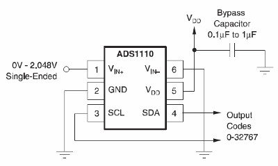
In this mode you can read a voltage that falls between zero and 2.048 V (which also happens to be the inbuilt reference voltage for the ADS1110). The example circuit is simple (from the data sheet):

singledemoDon’t forget the 10kΩ pull-up resistors on the I2C bus. The following sketch uses the ADS1110 in the default mode, and simply returns the voltage measured (download):

// Example 53.1 - ADS1110 single-sided voltmeter (0~2.048VDC)
#include "Wire.h"
#define ads1110 0x48
float voltage, data; 
byte highbyte, lowbyte, configRegister;
void setup() 
{ 
 Serial.begin(9600); 
 Wire.begin(); 
}
void loop() 
{ 
 Wire.requestFrom(ads1110, 3); 
 while(Wire.available()) // ensure all the data comes in 
 { 
 highbyte = Wire.read(); // high byte * B11111111
 lowbyte = Wire.read(); // low byte
 configRegister = Wire.read(); 
 } 

 data = highbyte * 256; 
 data = data + lowbyte;
 Serial.print("Data >> "); 
 Serial.println(data, DEC); 
 Serial.print("Voltage >> "); 
 voltage = data * 2.048 ;
 voltage = voltage / 32767.0; 
 Serial.print(voltage, DEC); 
 Serial.println(" V"); 
 delay(1000);
}

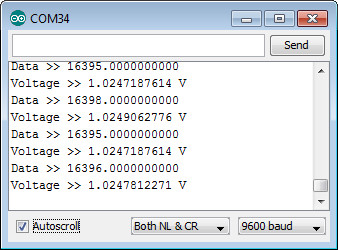
Once uploaded, connect the signal to measure and open the serial monitor – you’ll be presented with something similar to:

singledemosm

If you need to alter the gain of the internal programmable gain amplifier of the ADC – you’ll need to write a new byte into the configuration register using:

 Wire.beginTransmission(ads1110);
 Wire.write(configuration byte); 
 Wire.endTransmission();

before requesting the ADC data. This would be 0x8D, 0x8E or 0x8F for gain values of 2, 4 and 8 respectively – and use 0x8C to reset the ADS1110 back to default.

Differential ADC mode

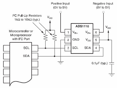
In this mode you can read the difference between two voltages that each fall between zero and 5 V. The example circuit is simple (from the data sheet):

diffcircuit

We must note here (and in the data sheet) that the ADS1110 can’t accept negative voltages on either of the inputs. You can use the previous sketch for the same results – and the resulting voltage will be the value of Vin- subtracted from Vin+. For example, if you had 2 V on Vin+ and 1 V on Vin- the resulting voltage would be 1 V (with the gain set to 1).

Conclusion

Once again I hope you found this of interest, and possibly useful. And if you enjoy my tutorials, or want to introduce someone else to the interesting world of Arduino – check out my new book “Arduino Workshop” from No Starch Press.

In the meanwhile have fun and keep checking into tronixstuff.com. Why not follow things on twitterGoogle+, subscribe  for email updates or RSS using the links on the right-hand column? And join our friendly Google Group – dedicated to the projects and related items on this website. Sign up – it’s free, helpful to each other –  and we can all learn something.


Jul
02

Tutorial – Arduino and the TI ADS1110 16-bit ADC

ADC, ads1110, analogue, arduino, converter, digital, i2c, instruments, lesson, texas, TI, tronixstuff, tutorial Comments Off on Tutorial – Arduino and the TI ADS1110 16-bit ADC 

Learn how to use the TI ADS1110 16-bit ADC with Arduino in chapter fifty-three of my Arduino Tutorials. The first chapter is here, the complete series is detailed here.

Updated 02/07/2013

Introduction

Moving on from the last chapter where we explained an 8-bit ADC, in this instalment we have the Texas Instruments ADS1110 – an incredibly tiny but useful 16-bit analogue-to-digital converter IC.  It can operate between 2.7 and 5.5 V so it’s also fine for Arduino Due and other lower-voltage development boards. This is a quick guide to get you going with the ADS1110 ready for further applications. Before continuing any further, please download the data sheet (pdf) as it will be useful and referred to during this tutorial. The ADS1110 gives you the option of a more accurate ADC than offered by the Arduino’s 10-bit ADCs – and it’s relatively easy to use. The only block for some is the package type – it’s only available in SOT23-6:

So unless you’re making a customised PCB, some sort of breakout will be required. One useful example is the Schmartboard we reviewed earlier:

ads1110schmartboard

The ADS1110 uses the I2C bus for communication, so if this is new to you – please review the I2C tutorials before continuing. And as there’s only six pins you can’t set the bus address – instead, you can select from six variants of the ADS1110 – each with their own address (see page two of the data sheet). As you can see the in the photo above, ours is marked “EDO” which matches to the bus address 1001000 or 0x48h. And with the example circuits we’ve used 10kΩ pull-up resistors on the I2C bus. You can use the ADS1110 as either a single-ended or differential ADC –  But first we need to examine the configuration register which is used to control various attributes, and the data register.

Configuration register

Turn to page eleven of the data sheet. The configuration register is one byte in size, and as the ADS1110 resets on a power-cycle – you need to reset the register if your needs are different to the defaults. The data sheet spells it out quite neatly… bits 0 and 1 determine the gain setting for the PGA (programmable gain amplifier). If you’re just measuring voltages or experimenting, leave these as zero for a gain of 1V/V. Next, the data rate for the ADS1110 is controlled with bits 2 and 3. If you have continuous sampling turned on, this determines the number of samples per second taken by the ADC.

After some experimenting with an Arduino Uno we found the values returned from the ADC were a bit off when using the fastest rate, so leave it as 15 SPS unless required otherwise. Bit 4 sets either continuous sampling (0) or one-off sampling (1). Ignore bits 5 and 6, however they’re always set as 0. Finally bit 7 – if you’re in one-off sampling mode, setting it to 1 requests a sample – and reading it will tell you if the returned data is new (0) or old (1). You can check that the value measured is a new value – if the first bit of the configuration byte that comes after the data is 0, it’s new. If it returns 1 the ADC conversion hasn’t finished.

Data register

As the ADS1110 is a 16-bit ADC, it returns the data over two bytes – and then follows with the value of the configuration register. So if you request three bytes the whole lot comes back. The data is in “two’s complement” form, which is a method of using signed numbers with binary. Converting those two bytes is done by some simple maths. When sampling at 15 SPS, the value returned by the ADS1110 (not the voltage)  falls between -32768 and 32767. The higher byte of the value is multiplied by 256, then added to the lower byte – which is then multiplied by 2.048 and finally divided by 32768. Don’t panic, as we do this in the example sketch below.

Single-ended ADC mode

In this mode you can read a voltage that falls between zero and 2.048 V (which also happens to be the inbuilt reference voltage for the ADS1110). The example circuit is simple (from the data sheet):

singledemoDon’t forget the 10kΩ pull-up resistors on the I2C bus. The following sketch uses the ADS1110 in the default mode, and simply returns the voltage measured:

// Example 53.1 - ADS1110 single-sided voltmeter (0~2.048VDC)

#include "Wire.h"
#define ads1110 0x48
float voltage, data;
byte highbyte, lowbyte, configRegister;
void setup()
{
 Serial.begin(9600);
 Wire.begin();
}
void loop()
{
 Wire.requestFrom(ads1110, 3);
 while(Wire.available()) // ensure all the data comes in
 {
 highbyte = Wire.read(); // high byte * B11111111
 lowbyte = Wire.read(); // low byte
 configRegister = Wire.read();
 }

 data = highbyte * 256;
 data = data + lowbyte;
 Serial.print("Data >> ");
 Serial.println(data, DEC);
 Serial.print("Voltage >> ");
 voltage = data * 2.048 ;
 voltage = voltage / 32768.0;
 Serial.print(voltage, DEC);
 Serial.println(" V");
 delay(1000);
}

Once uploaded, connect the signal to measure and open the serial monitor – you’ll be presented with something similar to:

singledemosm

If you need to alter the gain of the internal programmable gain amplifier of the ADC – you’ll need to write a new byte into the configuration register using:

Wire.beginTransmission(ads1110);
Wire.write(configuration byte); 
Wire.endTransmission();

before requesting the ADC data. This would be 0x8D, 0x8E or 0x8F for gain values of 2, 4 and 8 respectively – and use 0x8C to reset the ADS1110 back to default.

Differential ADC mode

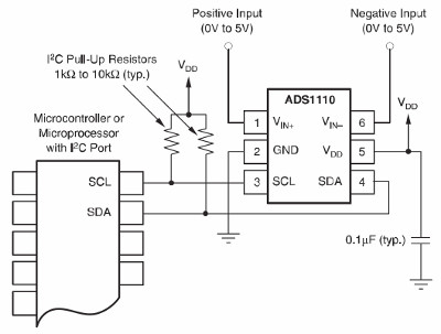
In this mode you can read the difference between two voltages that each fall between zero and 5 V. The example circuit is simple (from the data sheet):

diffcircuit

We must note here (and in the data sheet) that the ADS1110 can’t accept negative voltages on either of the inputs. You can use the previous sketch for the same results – and the resulting voltage will be the value of Vin- subtracted from Vin+. For example, if you had 2 V on Vin+ and 1 V on Vin- the resulting voltage would be 1 V (with the gain set to 1).

Conclusion

Once again I hope you found this of interest, and possibly useful. And if you enjoy my tutorials, or want to introduce someone else to the interesting world of Arduino – check out my new book “Arduino Workshop” from No Starch Press.

LEDborder

In the meanwhile have fun and keep checking into tronixstuff.com. Why not follow things on twitterGoogle+, subscribe  for email updates or RSS using the links on the right-hand column? And join our friendly Google Group – dedicated to the projects and related items on this website. Sign up – it’s free, helpful to each other –  and we can all learn something.

The post Tutorial – Arduino and the TI ADS1110 16-bit ADC appeared first on tronixstuff.


  • Newsletter

    Sign up for the PlanetArduino Newsletter, which delivers the most popular articles via e-mail to your inbox every week. Just fill in the information below and submit.

  • Like Us on Facebook