Posts | Comments

Planet Arduino

Archive for the ‘remote’ Category

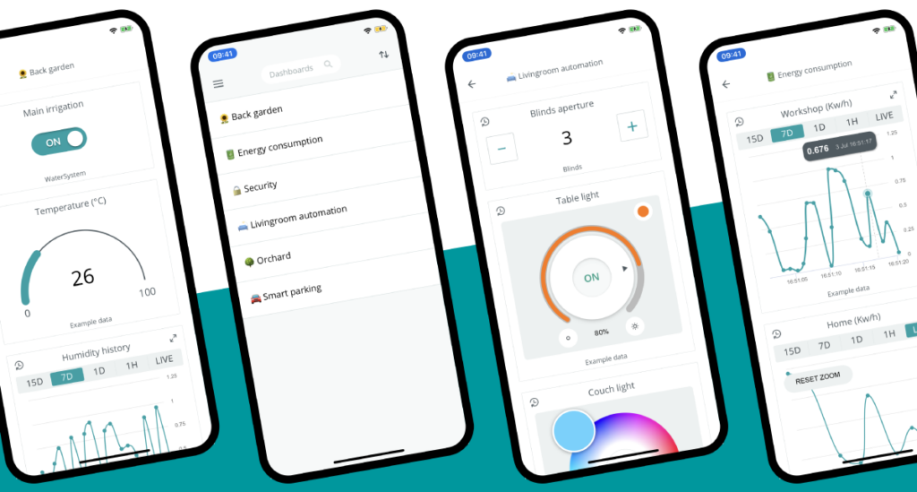
The perfect companion to the Arduino IoT Cloud! Develop your IoT solution online via a desktop, then monitor and control your dashboards on your mobile with the new Arduino IoT Cloud Remote app.

Initially available for free for iPhone on the App Store (Android to follow in the next few weeks), the Arduino IoT Cloud Remote app gives you with the ability to access, monitor or control your IoT projects regardless of the time or place:

  • In the field: you can read the data from your soil sensors or start your irrigation system directly from anywhere. 
  • In the factory: constant visibility of the state of your manufacturing process status, with the ability to control your automation remotely. 
  • In the home: monitor your home automation systems, check your previous or actual energy consumption from the convenience of your sofa.

The latest dashboard for the Arduino IoT Cloud comes with a host of enhanced features. Creating your dashboard via a desktop or tablet is quick and easy. The tool automatically configures your devices (including the secure crypto element) and automatically generates the main code for your project, making setup as straightforward as possible. A broad set of simple widgets to connect to the properties provides maximum versatility and enables you to set up a new dashboard in minutes.

Your dashboards, how you like them — all dashboards are fully customizable, it’s possible to group devices and organize them in any sequence — just drag and drop to arrange the layout, and select from multiple options including graphs to visualize the data. You can gather and display data from multiple IoT devices in one dashboard, and control those devices as required through your dashboard to fully integrate your solution. 

The addition of the Arduino IoT Cloud Remote app to access, monitor, and control dashboards on the go via your phone is the final piece of the jigsaw. 

iOS version is now available for free from the App Store.

[LittleTern] — annoyed by repetitive advertisements — wanted the ability to mute their Satellite Box for the duration of every commercial break. Attempts to crack their Satellite Box’s IR protocol went nowhere, so they thought — why not simply mute the TV?

Briefly toying with the idea of a separate remote for the function, [LittleTern] discarded that option as quickly as one tends to lose an additional remote. Instead, they’re using the spare RGYB buttons on their Sony Bravia remote — cutting down on total remotes while still controlling the IR muting system. Each of the four coloured buttons normally don’t do much, so they’re set do different mute length timers — customized for the channel or time of day. The system that sends the code to the TV is an Arduino Pro Mini controlling an IR LED and receiver, with a status LED set to glow according to which button was pressed.

With the helpful documentation from [Ken Shirriff]’s research into IR remotes — yes, that [Ken Schirriff] — [LittleTern] had the needed codes for their TV in hand and a programmed and ready Arduino. They were able to 3D print a project box, attach it to their TV near its IR receiver, and power it off its USB! Bonus!

[LittleTern] has provided their code in their blog post. There’s a little timing tinkering that needs to be done to ensure it works smoothly with a given setup, but otherwise, gone are the days of fumbling for the remote as your program resumes!

Ever on the lookout for creative applications for tech, [Andres Leon] built a solar powered battery system to keep his Christmas lights shining. It worked, but — pushing for innovation — it is now capable of so much more.

The shorthand of this system is two, 100 amp-hour, deep-cycle AGM batteries charged by four, 100 W solar panels mounted on an adjustable angle wood frame. Once back at the drawing board, however, [Leon] wanted to be able track real-time statistics of power collected, stored and discharged, and the ability to control it remotely. So, he introduced a Raspberry Pi running Raspbian Jessie Lite that publishes all the collected data to Home Assistant to be accessed and enable control of the system from the convenience of his smartphone. A pair of Arduino Deuemilanoves reporting to the Pi control a solid state relay powering a 12 V, 800 W DC-to-AC inverter and monitor a linear current sensor — although the latter still needs some tinkering. A in-depth video tour of the system follows after the break!

All the electronics are housed in a climate-controlled box which kicks on when the Pi’s CPU heats up — this is in a Florida backyard, folks — and powered off the battery system, with a handful of 40amp breakers between the components keep things safe. [Leon] has helpfully provided links to all the resources he used, as well as his code on GitHub.

We love homebrew solar power systems, but if only there was some way to take them on the road with us.


Filed under: Arduino Hacks, Raspberry Pi, solar hacks

[Dan], admirably rose to the occasion when his son wanted a new toy. Being a dedicated father — and instead of buying something new — he took the opportunity to abscond to his workbench to convert a Wiimote Nunchuck into a fully wireless controller for his son’s old r/c car — itself, gutted and rebuilt some years earlier.

Unpacking the nunchuck and corralling the I2C wires was simply done. From there, he combined a bit of code, an Arduino pro mini, and two 1K Ohm resistors to make use of an Aurel RTX-MID transceiver that had been lying around. Waste not, want not.

A TI Stellaris Launchpad is the smarts of the car itself, in concordance with a TB6612FNG motor controller. The two Solarbotics GM9 motors with some 3D printed gears give the car some much needed gusto.

In Dan’s own humble words: “nothing out of the ordinary, just a nice example of what one can do with parts mostly gathering dust around any hacker’s house.” If any new parents out there have a spare Wiimote stashed away, you can use the infrared LEDs to make a fairly effective baby monitor.


Filed under: Arduino Hacks, toy hacks

If you’ve built yourself a home theater PC, one of your highest priorities is probably coming up with a convenient control solution. The easiest way to do this is to simply use something like a wireless keyboard and mouse. But, that’s not very conducive to an enjoyable home theater experience, and it feels pretty clunky. However, if you’ve got the right components lying around, [Sebastian Goscik] has instructions and an Arduino sketch that will let you control your HTPC with any IR remote control.

There are a number of ways you could control your HTPC, and we’ve featured more than one build specifically for controlling XBMC over the years. Unfortunately, most of those methods require that you spend your hard earned money (which is better spent on popcorn). [Sebastian’s] setup can be replicated with things you probably have on hand: an Arduino, an IR remote, and a scavenged IR receiver. The IR receiver can be found in many devices, like old stereos or TVs that themselves were controlled via an IR remote.

It starts with an Arduino Sketch that lets you can see on the serial monitor what code is being generated by the button presses on your remote. These are then scripted to perform any task or function you like when those buttons are pushed. The most obvious use here is simple directional control for selecting your movies, but much more complex tasks are possible. Maybe someone can program a T9 script to type using the number buttons on most remotes?


Filed under: Arduino Hacks, home entertainment hacks
Jul
18

Arduino And IR Remote Turn Off Raspberry Pi

arduino, arduino hacks, IR, Raspberry Pi, remote, remote control, shutdown, uart Comments Off on Arduino And IR Remote Turn Off Raspberry Pi 

With all of the cool features on the Raspberry Pi, it is somewhat notable that it lacks a power button. In a simple setup, the only way to cut power to the tiny computer is to physically remove the power cord. [Dalton63841] found that this was below his wife’s tolerance level for electronics, and built a simple remote control for his Raspberry Pi.

[Dalton63841] started this project by trying to use the UART TX pin, but this turned out to be a dead-end. He decided instead to use an Arduino to monitor the 3.3V power rail on the Pi. When the Pi is shut down in software, the Arduino can sense that the Pi isn’t on any more and disconnect the power. The remote control is used to turn the Pi on. The Arduino reads the IR code from a remote and simply powers up the Pi. This is a very simple and elegant solution that requires absolutely no software to be installed on the Raspberry Pi.

We know that this isn’t the most technically complex project we’ve ever featured, but it is a good beginner project for anyone just getting started with a Pi, Arduino, or using IR. Plus, this could be the perfect thing to pair up with a battery-backup Raspberry Pi shutdown device that allows it to power itself down in a controlled way when a power outage is sensed.


Filed under: Arduino Hacks

[Joedefa] had a Griffin Beacon Universal Remote that was collecting dust, and decided that it needed to stop collecting dust. He had a growing number of wireless devices in his house and found himself in need of a remote to control them all. The Griffin Beacon fit the bill, but most of his lights and outlets were RF controlled. So he did what hackers do best… broke out the screw driver and soldering iron and rewired it!

[Joedefa] is using an Attiny85 as the brains between an infrared LED and a RF transmit module (if anyone can identify the source of this module, please let everyone know in the comments).  A pair of red and green LEDs lets him know if the remote has received commands successfully.

It’s always nice to see a discontinued product made useful once more with a little ingenuity and an Arduino some hacking skill. Hat’s off to [Joedefa] for a righteous hack!


Filed under: Arduino Hacks, ATtiny Hacks

Gesture Controlled Quadcopter

[grassjelly] has been hard at work building a wearable device that uses gestures to control quadcopter motion. The goal of the project is to design a controller that allows the user to intuitively control the motion of a quadcopter. Based on the demonstration video below, we’d say they hit the nail on the head. The controller runs off an Arduino Pro Mini-5v powered by two small coin cell batteries. It contains an accelerometer and an ultrasonic distance sensor.

The controller allows the quadcopter to mimic the orientation of the user’s hand. The user holds their hand out in front of them, parallel to the floor. When the hand is tilted in any direction, the quadcopter copies the motion and will tilt the same way. The amount of pitch and roll is limited by software, likely preventing the user from over-correcting and crashing the machine. The user can also raise or lower their hand to control the altitude of the copter.

[grassjelly] has made all of the code and schematics available via github.


Filed under: Arduino Hacks, drone hacks
May
31

Bare Bones Arduino IR Receiver

arduino, arduino hacks, Infrared, IR, IR emitter, remote, remote control, TV remote Comments Off on Bare Bones Arduino IR Receiver 

TV Remote

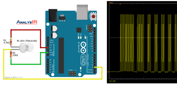
Old infrared remote controls can be a great way to interface with your projects. One of [AnalysIR's] latest blog posts goes over the simplest way to create an Arduino based IR receiver, making it easier than ever to put that old remote to good use.

Due to the popularity of their first IR receiver post, the silver bullet IR receiver, [AnalysIR] decided to write a quick post about using IR on the Arduino. The part list consists of one Arduino, two resistors, and one IR emitter. That’s right, an emitter. When an LED (IR or otherwise) is reverse biased it can act as a light sensor. The main difference when using this method is that the IR signal is not inverted as it would normally be when using a more common modulated IR receiver module. All of the Arduino code you need to get up and running is also provided. The main limitation when using this configuration, is that the remote control needs to be very close to the IR emitter in order for it to receive the signal.

What will you control with your old TV remote? It would be interesting to see this circuit hooked up so that a single IR emitter can act both as a transmitter and a receiver. Go ahead and give it a try, then let us know how it went!


Filed under: Arduino Hacks

Learn how to connect your Arduino to the outside world via Ethernet

This is chapter sixteen of our huge Arduino tutorial seriesUpdated 06/12/2013

In this chapter we will introduce and examine the use of Ethernet networking with Arduino over local networks and the greater Internet. It will be assumed that you have a basic understanding of computer networking, such as the knowledge of how to connect computers to a hub/router with RJ45 cables, what an IP and MAC address is, and so on. Furthermore, here is a good quick rundown about Ethernet.

Getting Started

You will need an Arduino Uno or compatible board with an Ethernet shield that uses the W5100 Ethernet controller IC (pretty much all of them):

Arduino Ethernet shield

…or consider using a Freetronics EtherTen – as it has everything all on the one board, plus some extras:

Freetronics EtherTen

Furthermore you will need to power the board via the external DC socket – the W5100 IC uses more current than the USB power can supply. A 9V 1A plug pack/wall wart will suffice. Finally it does get hot – so be careful not to touch the W5100 after extended use. In case you’re not sure – this is the W5100 IC:

Wiznet W5100

Once you have your Ethernet-enabled Arduino, and have the external power connected – it’s a good idea to check it all works. Open the Arduino IDE and selectFile > Examples > Ethernet > Webserver. This loads a simple sketch which will display data gathered from the analogue inputs on a web browser. However don’t upload it yet, it needs a slight modification.

You need to specify the IP address of the Ethernet shield – which is done inside the sketch. This is simple, go to the line:

IPAddress ip(192,168,1, 177);

And alter it to match your own setup. For example, in my home the router’s IP address is 10.1.1.1, the printer is 10.1.1.50 and all PCs are below …50. So I will set my shield IP to 10.1.1.77 by altering the line to:

IPAddress ip(10,1,1,77);

You also have the opportunity to change your MAC address. Each piece of networking equipment has a unique serial number to identify itself over a network, and this is normall hard-programmed into the equipments’ firmware. However with Arduino we can define the MAC address ourselves.

If you are running more than one Ethernet shield on your network, ensure they have different MAC addresses by altering the hexadecimal values in the line:

byte mac[] = { 0xDE, 0xAD, 0xBE, 0xEF, 0xFE, 0xED };

However if you only have one shield just leave it be. There may be the very, very, statistically rare chance of having a MAC address the same as your existing hardware, so that would be another time to change it.

Once you have made your alterations, save and upload the sketch. Now open a web browser and navigate to the IP address you entered in the sketch, and you should be presented with something similar to the following:

 Arduino webserver example sketch

What’s happening? The Arduino has been programmed to offer a simple web page with the values measured by the analogue inputs. You can refresh the browser to get updated values.

At this point – please note that the Ethernet shields use digital pins 10~13, so you can’t use those for anything else. Some Arduino Ethernet shields may also have a microSD card socket, which also uses another digital pin – so check with the documentation to find out which one.

Nevertheless, now that we can see the Ethernet shield is working we can move on to something more useful. Let’s dissect the previous example in a simple way, and see how we can distribute and display more interesting data over the network. For reference, all of the Ethernet-related functions are handled by the Ethernet Arduino library. If you examine the previous sketch we just used, the section that will be of interest is:

 for (int analogChannel = 0; analogChannel < 6; analogChannel++) 
          {
            int sensorReading = analogRead(analogChannel);
            client.print("analog input ");
            client.print(analogChannel);
            client.print(" is ");
            client.print(sensorReading);
            client.println("<br />");       
          }
          client.println("</html>");

Hopefully this section of the sketch should be familiar – remember how we have used serial.print(); in the past when sending data to the serial monitor box? Well now we can do the same thing, but sending data from our Ethernet shield back to a web browser – on other words, a very basic type of web page.

However there is something you may or may not want to  learn in order to format the output in a readable format – HTML code. I am not a website developer (!) so will not delve into HTML too much.

However if you wish to serve up nicely formatted web pages with your Arduino and so on, here would be a good start. In the interests of simplicity, the following two functions will be the most useful:

client.print(" is ");

Client.print (); allows us to send text or data back to the web page. It works in the same way as serial.print(), so nothing new there. You can also specify the data type in the same way as with serial.print(). Naturally you can also use it to send data back as well. The other useful line is:

client.println("<br />");

which sends the HTML code back to the web browser telling it to start a new line. The part that actually causes the carriage return/new line is the <br /> which is an HTML code (or “tag”) for a new line. So if you are creating more elaborate web page displays, you can just insert other HTML tags in the client.print(); statement. If you want to learn more about HTML commands, here’s a good tutorial site. Finally – note that the sketch will only send the data when it has been requested, that is when it has received a request from the web browser.

Accessing your Arduino over the Internet

So far – so good. But what if you want to access your Arduino from outside the local network?

You will need a static IP address – that is, the IP address your internet service provider assigns to your connection needs to stay the same. If you don’t have a static IP, as long as you leave your modem/router permanently swiched on your IP shouldn’t change. However that isn’t an optimal solution.

If your ISP cannot offer you a static IP at all, you can still move forward with the project by using an organisation that offers a Dynamic DNS. These organisations offer you your own static IP host name (e.g. mojo.monkeynuts.com) instead of a number, keep track of your changing IP address and linking it to the new host name. From what I can gather, your modem needs to support (have an in-built client for…) these DDNS services. As an example, two companies are No-IP andDynDNS.com. Please note that I haven’t used those two, they are just offered as examples.

Now, to find your IP address… usually this can be found by logging into your router’s administration page – it is usually 192.168.0.1 but could be different. Check with your supplier or ISP if they supplied the hardware. For this example, if I enter 10.1.1.1 in a web browser, and after entering my modem administration password, the following screen is presented:

WAN IP address router

What you are looking for is your WAN IP address, as you can see in the image above. To keep the pranksters away, I have blacked out some of my address.

The next thing to do is turn on port-forwarding. This tells the router where to redirect incoming requests from the outside world. When the modem receives such a request, we want to send that request to the port number of our Ethernet shield. Using the:

EthernetServer server(125);

function in our sketch has set the port number to 125. Each modem’s configuration screen will look different, but as an example here is one:

Arduino router port forwarding

So you can see from the line number one in the image above, the inbound port numbers have been set to 125, and the IP address of the Ethernet shield has been set to 10.1.1.77 – the same as in the sketch.

After saving the settings, we’re all set. The external address of my Ethernet shield will be the WAN:125, so to access the Arduino I will type my WAN address with :125 at the end into the browser of the remote web device, which will contact the lonely Ethernet hardware back home.

Furthermore, you may need to alter your modem’s firewall settings, to allow the port 125 to be “open” to incoming requests. Please check your modem documentation for more information on how to do this.

Now from basically any Internet connected device in the free world, I can enter my WAN and port number into the URL field and receive the results. For example, from a phone when it is connected to the Internet via LTE mobile data:

Arduino webserver example cellular

So at this stage you can now display data on a simple web page created by your Arduino and access it from anywhere with unrestricted Internet access. With your previous Arduino knowledge (well, this is chapter sixteen) you can now use data from sensors or other parts of a sketch and display it for retrieval.

Displaying sensor data on a web page

As an example of displaying sensor data on a web page, let’s use an inexpensive and popular temperature and humidity sensor – the DHT22. You will need to install the DHT22 Arduino library which can be found on this page. If this is your first time with the DHT22, experiment with the example sketch that’s included with the library so you understand how it works.

Connect the DHT22 with the data pin to Arduino D2, Vin to the 5V pin and GND to … GND:

arduino ethernet freetronics etherten dht22 humid

Now for our sketch – to display the temperature and humidity on a web page. If you’re not up on HTML you can use online services such as this to generate the code, which you can then modify to use in the sketch.

In the example below, the temperature and humidity data from the DHT22 is served in a simple web page:

#include <SPI.h>
#include <Ethernet.h>

// for DHT22 sensor
#include "DHT.h"
#define DHTPIN 2
#define DHTTYPE DHT22

// Enter a MAC address and IP address for your controller below.
// The IP address will be dependent on your local network:
byte mac[] = {   0xDE, 0xAD, 0xBE, 0xEF, 0xFE, 0xED };
IPAddress ip(10,1,1,77);

// Initialize the Ethernet server library
// with the IP address and port you want to use 
// (port 80 is default for HTTP):
EthernetServer server(125);
DHT dht(DHTPIN, DHTTYPE);

void setup() 
{
  dht.begin();
 // Open serial communications and wait for port to open:
  Serial.begin(9600);
   while (!Serial) {
    ; // wait for serial port to connect. Needed for Leonardo only
  }
  // start the Ethernet connection and the server:
  Ethernet.begin(mac, ip);
  server.begin();
  Serial.print("server is at ");
  Serial.println(Ethernet.localIP());
}

void loop() 
{
  // listen for incoming clients
  EthernetClient client = server.available();
  if (client) {
    Serial.println("new client");
    // an http request ends with a blank line
    boolean currentLineIsBlank = true;
    while (client.connected()) {
      if (client.available()) {
        char c = client.read();
        Serial.write(c);
        // if you've gotten to the end of the line (received a newline
        // character) and the line is blank, the http request has ended,
        // so you can send a reply
        if (c == 'n' && currentLineIsBlank) 
        {
          // send a standard http response header
          client.println("HTTP/1.1 200 OK");
          client.println("Content-Type: text/html");
          client.println("Connection: close");  // the connection will be closed after completion of the response
	  client.println("Refresh: 30");  // refresh the page automatically every 30 sec
          client.println();
          client.println("<!DOCTYPE HTML>");
          client.println("<html>");

          // get data from DHT22 sensor
          float h = dht.readHumidity();
          float t = dht.readTemperature();
          Serial.println(t);
          Serial.println(h);

          // from here we can enter our own HTML code to create the web page
          client.print("<head><title>Office Weather</title></head><body><h1>Office Temperature</h1><p>Temperature - ");
          client.print(t);
          client.print(" degrees Celsius</p>");
          client.print("<p>Humidity - ");
          client.print(h);
          client.print(" percent</p>");
          client.print("<p><em>Page refreshes every 30 seconds.</em></p></body></html>");
          break;
        }
        if (c == 'n') {
          // you're starting a new line
          currentLineIsBlank = true;
        } 
        else if (c != 'r') {
          // you've gotten a character on the current line
          currentLineIsBlank = false;
        }
      }
    }
    // give the web browser time to receive the data
    delay(1);
    // close the connection:
    client.stop();
    Serial.println("client disonnected");
  }
}

It is a modification of the IDE’s webserver example sketch that we used previously – with a few modifications. First, the webpage will automatically refresh every 30 seconds – this parameter is set in the line:

client.println("Refresh: 30");  // refresh the page automatically every 30 sec

… and the custom HTML for our web page starts below the line:

// from here we can enter our own HTML code to create the web page

You can then simply insert the required HTML inside client.print() functions to create the layout you need.

Finally – here’s an example screen shot of the example sketch at work:

arduino ethernet freetronics etherten dht22 humid cellular

You now have the framework to create your own web pages that can display various data processed with your Arduino.

Remote control your Arduino from afar
We have a separate tutorial on this topic, that uses the teleduino system.

Conclusion

So there you have it, another useful way to have your Arduino interact with the outside world. Stay tuned for upcoming Arduino tutorials by subscribing to the blog, RSS feed (top-right), twitter or joining our Google Group. And if you enjoyed the tutorial, or want to introduce someone else to the interesting world of Arduino – check out my book (now in a third printing!) “Arduino Workshop” from No Starch Press.

tronixstuff


  • Newsletter

    Sign up for the PlanetArduino Newsletter, which delivers the most popular articles via e-mail to your inbox every week. Just fill in the information below and submit.

  • Like Us on Facebook