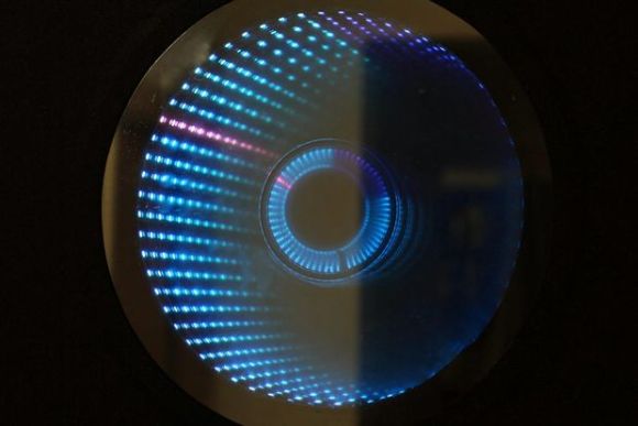
We don’t think we’ve seen an Infinity Mirror Clock before, but we love this new twist on an old favorite. Different colors distinguish between seconds, minutes and hours, and an additional IR sensor detects when someone is directly in front of the clock and switches the LEDs off, allowing it to be used as a normal mirror. This build is the work of [Dushyant Ahuja], who is no stranger to hacking together clocks out of LEDs. You can tell how much progress he’s made with the mirror clock by taking a glance at his first project, which is an impressive creation held together by jumbles of wire and some glue.
[Dushyant] has stepped up his game for his new clock, attaching an LED strip along the inside of a circular frame to fashion the infinity mirror effect. The lights receive a signal from an attached homemade Arduino board, which is also connected to a real-time clock (RTC) module to keep time and to a Bluetooth module, which allows [Dushyant] to program the clock wirelessly rather than having to drag out some cords if the clock ever needs an adjustment.
Stick around after the jump for a quick demonstration video. The lights are dazzling to watch; [Dushyant] inserted a stainless steel plate at the center of the circle to reflect the outer rim of LEDs. After a quick rainbow effect, it looks like the mirror enters clock mode. See if you can figure out what time it is. For a more step-by-step overview of this project, swing by his Instructables page.
Some of the more in-your-face pieces of wearable technology are macetech’s RGB Shades and LED Matrix Shades. They’re shutter shade sunglasses with a twist: the front surface is crammed with individually controllable LEDs. It’s an attention-grabbing effect, and the person wearing the Shades can see through the LED array just […]
Choose the hue of light that makes you feel more comfortable.
Simple bluetooth remote control from which you can modify lighting from your mobile device or tablet.
- You have two separate RGB channels where you can get different colors per channel.
- Control adjustable intensity.
- Do it yourself .
- Thanks to the arduino platform in minutes you ‘ll Omniblug armed and ready for use.
Discover all the features provided. Is very easy install this small device.
arduino, ldr, LED, OLED, RGBComments Off on Simple technique of sensing colors using Arduino
ZXLee built a simple sensor for Arduino which allows him to detect colors. The idea lies behind using red, green, blue LEDs and Light Dependent Resistor (LDR). Lee Zhi Xian writes:
Previously I have made a colour sensor using Arduino but don’t have the time to update it on my blog. Today I am going to share the details of this mini project. Basically, the sensor consists of three LEDs and Light Dependent Resistor (LDR). The LDR will detect the colour and display it to another RGB LED. Besides display it on the RGB LED, the colour will also display on PC. RGB LED is commonly used in display colours on LCD or OLED such as the monitor and television.
Don’t let the above picture’s lack of blinking colors fool you, the light-up dress [Sam] fashioned for his girlfriend is rather eye-catching; we’d just rather talk about it than edit the gifs he’s provided. [Sam's] been a busy guy. His last project was a Raspberry Pi digital photo frame, which we featured just over a week ago, but wearable hacks allow him to combine his favored hobbies of sewing and electronics.
If you’re looking to get started with wearable electronics, then this project provides a great entry point. The bulk of the build is what you’d expect: some individually-addressable RGB LEDs, the ever-popular FLORA board from Adafruit, and a simple battery holder. [Sam] decided to only use around 40 of the LEDs, but the strips come 60 to a meter, so he simply tucked the extra away inside the dress and set his desired limits in the software, which will allow him to preserve the entire strip for future projects. If you’ve ever attempted a wearable hack, you’re probably familiar with how delicate the connections can be and how easily the slightest bend in the wiring can leave you stranded. Most opt for a conductive thread solution, but [Sam] tried something different and used 30 AWG wire, which was thin enough to be sewn into the fabric. As an added bonus, the 30 AWG wire is insulated, which permits him to run the wires close to (or perhaps over) each other while avoiding shorts. [Sam's] guide is detailed and approachable, so head over to his project page if you think you’ve caught wearables fever, and check out his GitHub for the source code.
The team from Incredible Machines have rigged up an Xmas tree using WiFi web-socket connected (and Arduino-powered) Visualight light bulbs and LED strips (crowdfunded back in October, 2012). You can interact with their "TreeeeeTMMMMM" at this website. If they're working nearby I apologize, because I keep setting colors to "blink fast" mode :)
[Philippe Chrétien's] project makes it to our front page just based on its completeness. When you hear about a multicolored lamp which changes based on an RFID tag you might not get too excited. When you look at the refined electronics and the quality of the wooden enclosure it’s another story entirely.
As we’ve said many times before, coming up with the idea for a project is the hardest part… especially when you just want to start hacking. With his kids in mind [Philippe] figured this would be something fun for them to play around with, opening the door to discussing the electronics concepts behind it.
He prototyped on a breadboard using three N-type MOSFETs to drive the colors of an RGB LED strip. The proven circuit was laid out and etched at home to arrive at the clean-looking Arduino shield shown off above. The entire thing gets a custom enclosure cut using layered plywood, a paper template, and a bandsaw.
Need a use for this once the novelty has worn off? Why not mod it to use as a motion activated night light? Alas the actual project link for that one is dead, but you get the idea.
BO.Duino is an Arduino compatible board based on ATmega328 ATMEL’s mcu. This board features many peripherals usually externally connected on a breadboard or prototyping board such as sensors, SD card etc. Peripherals included are:
- A real-time clock
- AT24 series external memory chip
- MicroSD card adaptor (SPI)
- RGB LED
- A potentiometer on analog input
- Connector for DS18b20 or DHt11 series sensors
A few weeks ago I was asked about creating a musical-effect display with an RGB LED cube kit from our friends over at Freetronics, and with a little work this was certainly possible using the MSGEQ7 spectrum analyzer IC. In this project we’ll create a small add-on PCB containing the spectrum analyzer circuit and show how it can drive the RGB LED cube kit.
You can get the bare MSGEQ7 ICs from Sparkfun and the other usual suspects. It never hurts to have a spare one, so order two and matching IC sockets. Finally you should be able to translate a simple circuit to prototyping board.
The circuit
The LED cube already has an Arduino Leonardo-compatible built in to the main PCB, so all you need to do is build a small circuit that contains the spectrum analyzer which connects to the I/O pins on the cube PCB and also has audio input and output connections. First, consider the schematic:
For the purposes of this project our spectrum analyzer will only display the results from one channel of audio – if you want stereo, you’ll need two! And note that the strobe, reset and DCOUT pins on the MSGEQ7 are labelled with the connections to the cube PCB. Furthermore the pinouts for the MSGEQ7 don’t match the physical reality – here are the pinouts from the MSGEQ7 data sheet (.pdf):
The circuit itself will be quite small and fit on a small amount of stripboard or veroboard. There is plenty of room underneath the cube to fit the circuit if so desired:
With a few moments you should be able to trace out your circuit to match the board type you have, remember to double-check before soldering. You will also need to connect the audio in point after the 1000 pF capacitor to a source of audio, and also pass it through so you can connect powered speakers, headphones, etc.
One method of doing so would be to cut up a male-female audio extension lead, and connect the shield to the GND of the circuit, and the signal line to the audio input on the circuit. Or if you have the parts handy and some shielded cable, just make your own input and output leads:
Be sure to test for shorts between the signal and shield before soldering to the circuit board. When finished, you should have something neat that you can hide under the cube or elsewhere:
Double-check your soldering for shorts and your board plan, then fit to the cube along with the audio source and speakers (etc).
Arduino Sketch
The sketch has two main functions – the first is to capture the levels from the MSGEQ7 and put the values for each frequency band into an array, and the second function is to turn on LEDs that represent the level for each band. If you’ve been paying attention you may be wondering how we can represent seven frequency bands with a 4x4x4 LED cube. Simple – by rotating the cube 45 degrees you can see seven vertical columns of LEDs:
So when looking from the angle as shown above, you have seven vertical columns, each with four levels of LEDs. Thus the strength of each frequency can be broken down into four levels, and then the appropriate LEDs turned on.
After this is done for each band, all the LEDs are turned off and the process repeats. For the sake of simplicity I’ve used the cube’s Arduino library to activate the LEDs, which also makes the sketch easier to fathom. The first example sketch only uses one colour:
// Freetronics CUBE4: and MSGEQ7 spectrum analyser
// MSGEQ7 strobe on A4, reset on D5, signal into A0

#include "SPI.h"
#include "Cube.h"
Cube cube;

int res = 5; // reset pins on D5
int left[7]; // store band values in these arrays
int band;

void setup()
{
  pinMode(res, OUTPUT); // reset
  pinMode(A4, OUTPUT); // strobe
  digitalWrite(res,LOW);
  digitalWrite(A4,HIGH);
  cube.begin(-1, 115200);
  Serial.begin(9600);
}

void readMSGEQ7()
// Function to read 7 band equalizers
{
  digitalWrite(res, HIGH);
  digitalWrite(res, LOW);
  for(band=0; band <7; band++)
  {
    digitalWrite(A4,LOW); // strobe pin on the shield - kicks the IC up to the next band
    delayMicroseconds(30); //
    left[band] = analogRead(0); // store band reading
    digitalWrite(A4,HIGH);
  }
}

void loop()
{
  readMSGEQ7();

  for (band = 0; band < 7; band++)
  {
    // div each band strength into four layers, each band then one of the odd diagonals

    // band one ~ 63 Hz
    if (left[0]>=768) {
      cube.set(3,3,3, BLUE);
    }
    else
      if (left[0]>=512) {
      cube.set(3,3,2, BLUE);
    }
    else
      if (left[0]>=256) {
      cube.set(3,3,1, BLUE);
    }
    else
      if (left[0]>=0) {
      cube.set(3,3,0, BLUE);
    }

    // band two ~ 160 Hz
    if (left[1]>=768)
    {
      cube.set(3,2,3, BLUE);
      cube.set(2,3,3, BLUE);
    }
    else
      if (left[1]>=512)
      {
        cube.set(3,2,2, BLUE);
        cube.set(2,3,2, BLUE);
      }
      else
        if (left[1]>=256)
      {
        cube.set(3,2,1, BLUE);
        cube.set(2,3,1, BLUE);
      }
      else
        if (left[1]>=0)
      {
        cube.set(3,2,0, BLUE);
        cube.set(2,3,0, BLUE);
      }

    // band three ~ 400 Hz
    if (left[2]>=768)
    {
      cube.set(3,1,3, BLUE);
      cube.set(2,2,3, BLUE);
      cube.set(1,3,3, BLUE);
    }
    else
      if (left[2]>=512)
      {
        cube.set(3,1,2, BLUE);
        cube.set(2,2,2, BLUE);
        cube.set(1,3,2, BLUE);
      }
      else
        if (left[2]>=256)
      {
        cube.set(3,1,1, BLUE);
        cube.set(2,2,1, BLUE);
        cube.set(1,3,1, BLUE);
      }
      else
        if (left[2]>=0)
      {
        cube.set(3,1,0, BLUE);
        cube.set(2,2,0, BLUE);
        cube.set(1,3,0, BLUE);
      }

    // band four ~ 1 kHz
    if (left[3]>=768)
    {
      cube.set(3,0,3, BLUE);
      cube.set(2,1,3, BLUE);
      cube.set(1,2,3, BLUE);
      cube.set(0,3,3, BLUE);
    }
    else
      if (left[3]>=512)
      {
        cube.set(3,0,2, BLUE);
        cube.set(2,1,2, BLUE);
        cube.set(1,2,2, BLUE);
        cube.set(0,3,2, BLUE);
      }
      else
        if (left[3]>=256)
      {
        cube.set(3,0,1, BLUE);
        cube.set(2,1,1, BLUE);
        cube.set(1,2,1, BLUE);
        cube.set(0,3,1, BLUE);
      }
      else
        if (left[3]>=0)
      {
        cube.set(3,0,0, BLUE);
        cube.set(2,1,0, BLUE);
        cube.set(1,2,0, BLUE);
        cube.set(0,3,0, BLUE);
      }

    // band five  ~ 2.5 kHz
    if (left[4]>=768)
    {
      cube.set(2,0,3, BLUE);
      cube.set(1,1,3, BLUE);
      cube.set(0,2,3, BLUE);
    }
    else
      if (left[4]>=512)
      {
        cube.set(2,0,2, BLUE);
        cube.set(1,1,2, BLUE);
        cube.set(0,2,2, BLUE);
      }
      else
        if (left[4]>=256)
      {
        cube.set(2,0,1, BLUE);
        cube.set(1,1,1, BLUE);
        cube.set(0,2,1, BLUE);
      }
      else
        if (left[4]>=0)
      {
        cube.set(2,0,0, BLUE);
        cube.set(1,1,0, BLUE);
        cube.set(0,2,0, BLUE);
      }

    // band six   ~ 6.25 kHz
    if (left[5]>=768)
    {
      cube.set(1,0,3, BLUE);
      cube.set(0,1,3, BLUE);
    }
    else
      if (left[5]>=512)
      {
        cube.set(1,0,2, BLUE);
        cube.set(0,1,2, BLUE);
      }
      else
        if (left[5]>=256)
      {
        cube.set(1,0,1, BLUE);
        cube.set(0,1,1, BLUE);
      }
      else
        if (left[5]>=0)
      {
        cube.set(1,0,0, BLUE);
        cube.set(0,1,0, BLUE);
      }

    // band seven  ~ 16 kHz
    if (left[6]>=768)
    {
      cube.set(0,0,3, BLUE);
    }
    else
      if (left[6]>=512)
      {
        cube.set(0,0,2, BLUE);
      }
      else
        if (left[6]>=256)
      {
        cube.set(0,0,1, BLUE);
      }
      else
        if (left[6]>=0)
      {
        cube.set(0,0,0, BLUE);
      }
  }
  // now clear the CUBE, or if that's too slow - repeat the process but turn LEDs off
  cube.all(BLACK);
}
… and a quick video demonstration:
For a second example, we’ve used various colours:
// Freetronics CUBE4: and MSGEQ7 spectrum analyser
// MSGEQ7 strobe on A4, reset on D5, signal into A0
// now in colour!

#include "SPI.h"
#include "Cube.h"
Cube cube;

int res = 5; // reset pins on D5
int left[7]; // store band values in these arrays
int band;
int additional=0;

void setup()
{
  pinMode(res, OUTPUT); // reset
  pinMode(A4, OUTPUT); // strobe
  digitalWrite(res,LOW);
  digitalWrite(A4,HIGH);
  cube.begin(-1, 115200);
  Serial.begin(9600);
}

void readMSGEQ7()
// Function to read 7 band equalizers
{
  digitalWrite(res, HIGH);
  digitalWrite(res, LOW);
  for(band=0; band <7; band++)
  {
    digitalWrite(A4,LOW); // strobe pin on the shield - kicks the IC up to the next band
    delayMicroseconds(30); //
    left[band] = analogRead(0) + additional; // store band reading
    digitalWrite(A4,HIGH);
  }
}

void loop()
{
  readMSGEQ7();

  for (band = 0; band < 7; band++)
  {
    // div each band strength into four layers, each band then one of the odd diagonals

    // band one ~ 63 Hz
    if (left[0]>=768) {
      cube.set(3,3,3, RED);
    }
    else
      if (left[0]>=512) {
      cube.set(3,3,2, YELLOW);
    }
    else
      if (left[0]>=256) {
      cube.set(3,3,1, YELLOW);
    }
    else
      if (left[0]>=0) {
      cube.set(3,3,0, BLUE);
    }

    // band two ~ 160 Hz
    if (left[1]>=768)
    {
      cube.set(3,2,3, RED);
      cube.set(2,3,3, RED);
    }
    else
      if (left[1]>=512)
      {
        cube.set(3,2,2, YELLOW);
        cube.set(2,3,2, YELLOW);
      }
      else
        if (left[1]>=256)
      {
        cube.set(3,2,1, YELLOW);
        cube.set(2,3,1, YELLOW);
      }
      else
        if (left[1]>=0)
      {
        cube.set(3,2,0, BLUE);
        cube.set(2,3,0, BLUE);
      }

    // band three ~ 400 Hz
    if (left[2]>=768)
    {
      cube.set(3,1,3, RED);
      cube.set(2,2,3, RED);
      cube.set(1,3,3, RED);
    }
    else
      if (left[2]>=512)
      {
        cube.set(3,1,2, YELLOW);
        cube.set(2,2,2, YELLOW);
        cube.set(1,3,2, YELLOW);
      }
      else
        if (left[2]>=256)
      {
        cube.set(3,1,1, YELLOW);
        cube.set(2,2,1, YELLOW);
        cube.set(1,3,1, YELLOW);
      }
      else
        if (left[2]>=0)
      {
        cube.set(3,1,0, BLUE);
        cube.set(2,2,0, BLUE);
        cube.set(1,3,0, BLUE);
      }

    // band four ~ 1 kHz
    if (left[3]>=768)
    {
      cube.set(3,0,3, RED);
      cube.set(2,1,3, RED);
      cube.set(1,2,3, RED);
      cube.set(0,3,3, RED);
    }
    else
      if (left[3]>=512)
      {
        cube.set(3,0,2, YELLOW);
        cube.set(2,1,2, YELLOW);
        cube.set(1,2,2, YELLOW);
        cube.set(0,3,2, YELLOW);
      }
      else
        if (left[3]>=256)
      {
        cube.set(3,0,1, YELLOW);
        cube.set(2,1,1, YELLOW);
        cube.set(1,2,1, YELLOW);
        cube.set(0,3,1, YELLOW);
      }
      else
        if (left[3]>=0)
      {
        cube.set(3,0,0, BLUE);
        cube.set(2,1,0, BLUE);
        cube.set(1,2,0, BLUE);
        cube.set(0,3,0, BLUE);
      }

    // band five  ~ 2.5 kHz
    if (left[4]>=768)
    {
      cube.set(2,0,3, RED);
      cube.set(1,1,3, RED);
      cube.set(0,2,3, RED);
    }
    else
      if (left[4]>=512)
      {
        cube.set(2,0,2, YELLOW);
        cube.set(1,1,2, YELLOW);
        cube.set(0,2,2, YELLOW);
      }
      else
        if (left[4]>=256)
      {
        cube.set(2,0,1, YELLOW);
        cube.set(1,1,1, YELLOW);
        cube.set(0,2,1, YELLOW);
      }
      else
        if (left[4]>=0)
      {
        cube.set(2,0,0, BLUE);
        cube.set(1,1,0, BLUE);
        cube.set(0,2,0, BLUE);
      }

    // band six   ~ 6.25 kHz
    if (left[5]>=768)
    {
      cube.set(1,0,3, RED);
      cube.set(0,1,3, RED);
    }
    else
      if (left[5]>=512)
      {
        cube.set(1,0,2, YELLOW);
        cube.set(0,1,2, YELLOW);
      }
      else
        if (left[5]>=256)
      {
        cube.set(1,0,1, YELLOW);
        cube.set(0,1,1, YELLOW);
      }
      else
        if (left[5]>=0)
      {
        cube.set(1,0,0, BLUE);
        cube.set(0,1,0, BLUE);
      }

    // band seven  ~ 16 kHz
    if (left[6]>=768)
    {
      cube.set(0,0,3, RED);
    }
    else
      if (left[6]>=512)
      {
        cube.set(0,0,2, YELLOW);
      }
      else
        if (left[6]>=256)
      {
        cube.set(0,0,1, YELLOW);
      }
      else
        if (left[6]>=0)
      {
        cube.set(0,0,0, BLUE);
      }
  }
  // now clear the CUBE, or if that's too slow - repeat the process but turn LEDs off
  cube.all(BLACK);
}
… and the second video demonstration:
A little bit of noise comes through into the spectrum analyzer, most likely due to the fact that the entire thing is unshielded. The previous prototype used the Arduino shield from the tutorial which didn’t have this problem, so if you’re keen perhaps make your own custom PCB for this project.
Conclusion
Well that was something different and I hope you enjoyed it, and can find use for the circuit. That MSGEQ7 is a handy IC and with some imagination you can create a variety of musically-influenced displays. And while you’re here – are you interested in learning more about Arduino? Then order my new book “Arduino Workshop” from No Starch Press.
In the meanwhile have fun and keep checking into tronixstuff.com. Why not follow things on twitter, Google+, subscribe for email updates or RSS using the links on the right-hand column? And join our friendly Google Group – dedicated to the projects and related items on this website. Sign up – it’s free, helpful to each other – and we can all learn something.
Planet Arduino is, or at the moment is wishing to become, an aggregation of public weblogs from around the world written by people who develop, play, think on Arduino platform and his son. The opinions expressed in those weblogs and hence this aggregation are those of the original authors. Entries on this page are owned by their authors. We do not edit, endorse or vouch for the contents of individual posts. For more information about Arduino please visit www.arduino.cc
You are currently browsing the archives for the RGB category.