Posts | Comments

Planet Arduino

Archive for the ‘CNC’ Category

How many of us have an everyday tool that’s truly unique? Likely not many of us; take a look around your desk and turn out your pockets, but more often than not, what you’ll find is that everything you have is something that pretty much everyone else on the planet could have bought too. But not so if you’ve got this beautiful custom RPN calculator in a wooden case.

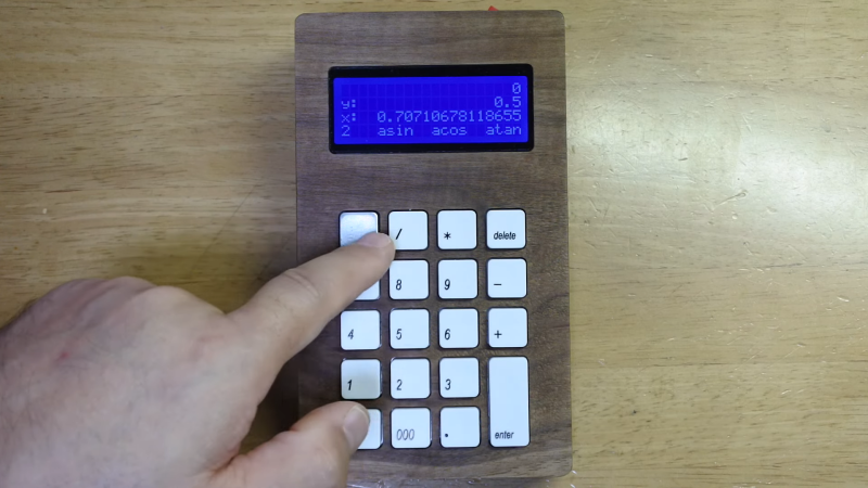
This one comes to us from [Shinsaku Hiura], who generally dazzles us with unique mechanical clocks and displays. This calculator solves a more practical problem — the dearth of RPN calculators on the market with the correct keyboard feel, specifically with the large keys and light touch he desired. Appropriately, the build started with a numeric keypad, which once liberated of its USB interface was reverse-engineered to figure out how the matrix was wired. Next up, a custom PCB to connect the keypad to an Arduino and a 20×4 LCD display was milled up, while a test case was designed and printed to check fitment. The final case was milled from a block of solid walnut and fitted with an acrylic window, for a sharp look with clean lines and pleasing colors.

As for the calculator itself, the demo below shows it going through its paces. The code is clever because it leverages the minimal number of keys available by hiding all the scientific and engineering functions behind a “secret silver key” that was once the equals key and obviously not needed in RPN. Hats off to [Shinsaku] for a handsome and unique addition to his desk.

We’ve seen plenty of people 3D printing custom gears over the years, but [Mr Innovative] decided against an additive process for his bespoke component. He ended up using a simple CNC machine that makes use of several components that were either salvaged from a 3D printer or produced on one. Using a small saw blade, the machine cuts gear teeth into some plastic material and — presumably — could cut gears into anything the saw blade was able to slice into, especially if you added a little lubrication, cooling, and dust removal.

If you’ve built a 3D printer, you’ll see a lot of familiar parts. Stepper motors, aluminum extrusion, straight rods, bearing blocks, and rod holders are all used in the build. There’s also a lead screw and the associated components you usually see in a printer’s Z-axis. Naturally, an Arduino drives the whole affair.

The saw blade was custom-made from a washer, grinding an edge and using a 3D printed template to cut teeth in it. We might have been more inclined to use a cut-off wheel from a rotary tool, but this certainly did the trick. An LCD accepts the gear diameter and number of teeth. The stepper rotates the correct number of degrees and another stepper lowers the cutting head which is spinning with a common DC motor.

As impressive as this machine is, the fact remains that a 3D printer can produce more complex designs. For example, a herringbone pattern can help with alignment issues. It has been done many times. You can even use a resin printer, although you might prefer to stick with FDM.

This Sun Tracking CNC Machine Uses The Sun Instead of a Laser

We’ve all seen people goof around with a magnifying glass in the sun, but this project takes it to a new level. Cranktown City has uploaded this fantastically amusing project that is sure to impress. He built a cnc controlled engraving machine that uses the sun instead of a laser tube. As he explains in […]

The post This Sun Tracking CNC Machine Uses The Sun Instead of a Laser appeared first on Make: DIY Projects and Ideas for Makers.

LED and LCD displays are a technological marvel. They’ve brought the price of televisions and monitors down to unheard-of levels since the days of CRTs, but this upside arguably comes with an aesthetic cost. When everything is covered in bland computer screens, the world tends to look a lot more monotonous. Not so several decades ago when there were many sharply contrasting ways of displaying information. One example of this different time comes to us by way of this split-flap display that [Erich] has been recreating.

Split-flap displays work by printing letters or numbers on a series of flaps that are attached to a spindle with a stepper motor. Each step of the motor turns the display by one character. They can be noisy and do require a large amount of maintenance compared to modern displays, but have some advantages as well. [Erich]’s version is built out of new acrylic and MDF, and uses an Arduino as the control board. A 3D printer and CNC machine keep the tolerances tight enough for the display to work smoothly and also enable him to expand the display as needed since each character display is fairly modular.

Right now, [Erich]’s display has 20 characters on two different rows and definitely brings us back to the bygone era where displays of this style would have been prominent in airports and train stations. This display uses a lot of the basics from another split flap display that we featured a few years ago but has some improvements. And, if you’d prefer restorations of old displays rather than modern incarnations, we have you covered there as well.

Thanks to [Bob] for the tip!

In their quest to create a portable CNC plotter, Instructables user tuenhidiy combined several PVC pieces with a couple of motors to build the P-CNC Plotter. The small machine — which was designed to resemble a quadruped robot — features an Arduino Uno and a Gbrl control shield at its heart that takes incoming G-code and translates it into motor movements. The X axis consists of a single NEMA-17 stepper motor that actuates a threaded rod to slide the rest of the device along a path. 

There is a central PVC assembly that holds both the threaded and smooth rods for both the X and Y axes while letting the entire thing move. Tuenhidiy was able to repurpose the linear gliding mechanism from a CD player as the Z axis, thus letting the pen or other drawing utensil go up and down with great precision. A set of three A4988 stepper motor driver modules provide the current to both the NEMA 17 motors and CD drive components. 

Images are drawn within the vector-based program Inkscape, and they normally include text, basic shapes, and splines that the toolhead can follow. G-code was exported from Inkscape by using an extension, and this could then be sent to the Gbrl-enabled Arduino. To read more about this project, you can check out tuenhidiy’s write-up here.

The post The P-CNC Plotter is a DIY drawing machine ‘disguised as a quadruped robot’ appeared first on Arduino Blog.

CNC plotters are a lot of fun to build and use, as they teach mechanics, electronics, and how G-code works. However, traditional Cartesian machines often require expensive components such as linear rods and ample amounts of bearings to move in just two axes. YouTuber DAZ Projects set out to change that by assembling a form of a Polargraph to draw pictures with great detail. The idea is simple: use a pair of stepper motors to alter the length of a string on two sides that controls where the toolhead goes. 

He started by 3D printing stepper motor mounts, a few pulleys for the string to wrap around, and the pen holding/lifting mechanism. Both 5V stepper motors plug into a generic Grbl CNC shield and are driven by a couple of A4988 modules. The servo is powered directly by an Arduino Uno, and its job is to adjust the pressure the pen applies to the page to change how dark the lines are. 

Once the custom firmware written by the Polargraph’s creator, Sandy Noble, was flashed to the Uno, DAZ connected it to his computer which was running the Polargraph control software. In here, the program takes an image and outputs a series of toolpaths for the Uno to convert to motor movements. You can see how DAZ constructed and used the device below, as well as the find the code on GitHub and 3D design files on Thingiverse

The post This may be one of the cheapest and easiest CNC drawing machines you’ll find appeared first on Arduino Blog.

We’ve seen a number of homemade CNC machines throughout the years, but Tuenhidiy’s build — made from some discarded materials — is no less impressive. This unique CNC plotter features a frame cleverly constructed out of two wooden wine boxes, which appear to be the perfect size with space for an Y-axis bed and an upright structure that actuates X movements. For the Z component, a pen is lifted using parts from a recycled CD player drive.

Electronics-wise, the project is also quite interesting as it employs servos rather than steppers for its X and Y axes. Actuation is handled by an Arduino Uno with pre-installed GRBL firmware and a CNC shield, which sends commands to an Arduino Mega running custom firmware. The Mega — plus a custom adapter board and an L293D shield — takes care of PID control for the motors.

More details on the machine can be found in Tuenhidiy’s write-up, and you can see it demonstrated in the video below.

The post Two Arduinos are used to control this DIY three-axis CNC plottee appeared first on Arduino Blog.

In theory, there’s isn’t much to building a CNC machine. Hook a bit to a motor and move the motor around with some lead screws and stepper motors. Easy. But, of course, the devil is in the details. [DAZ] made a nice-looking and inexpensive rig that probably isn’t the most precise CNC in the world, but it looks like it does a good enough job and he claims he spent about $50 on it. The video below shows some of the work it has done, and it doesn’t look bad.

This isn’t a rainy afternoon project. You’ll need to cut some wood and 3D print many parts. The drives use M8 threaded rod. Electronics is just an Arduino running standard software.

The steppers looked pretty light duty, and we wondered if it would have been worthwhile to trade them out for beefier ones instead of modifying the ones used for bipolar operation. Still, the results did look good for $50. The 775 spindle is another place you could probably spend a little more and get something better. Non-printed linear rails, and a better screw? The point is that you’ve got a basis to build from.

We’ve seen cheap CNCs made from scrap before. If you decide an Arduino is too low-powered for your CNC, try going 32-bit.

To label used bottles that would otherwise go to waste, “tuenhidiy” created a CNC bottle plotter that itself consists mostly of scraps!

The machine’s X and Z axes are formed out of a pair of old CD/DVD players, but instead of a traditional Y axis, it actuates two printer rollers to turn a bottle forwards or backwards. This allows the marking pen to be placed in just the right axial position, while still being very similar to a fully Cartesian (XYZ) plotter controls-wise.

Everything is powered by GRBL running on an Arduino Uno, which interfaces with its four steppers via a CNC shield and A4988 driver modules. Build info is available in tuenhidiy’s write-up, and you also check it out in the video below.

Ask anybody whose spent time standing in front of a mill or lathe and they’ll tell you that some operations can get tedious. When you need to turn down a stainless rod by 1/4″ in 0.030″ increments, you get a lot of time to reflect on why you didn’t just buy the right size stock as you crank the wheel back and forth. That’s where the lead screw comes in — most lathes have a gear-driven lead screw that can be used to actuate the z-axis ( the one which travels parallel to the axis of rotation). It’s no CNC, but this type of gearing makes life easier and it’s been around for a long time.

[Tony Goacher] took this idea a few steps further when he created the Leadscrew Buddy. He coupled a beautiful 1949 Myford lathe with an Arduino, a stepper motor, and a handful of buttons to add some really useful capabilities to the antique machine. By decoupling the lead screw from the lathe’s gearbox and actuating it via a stepper motor, he achieved a much more granular variable feed speed.

If that’s not enough, [Tony] used a rotary encoder to display the cutting tool’s position on a home-built Digital Readout (DRO). The pièce de résistance is a “goto” command. Once [Tony] sets a home position, he can command the z-axis to travel to a set point at a given speed. Not only does this make turning easier, but it makes the process more repeatable and yields a smoother finish on the part.

These features may not seem so alien to those used to working with modern CNC lathes, but to the vast majority of us garage machinists, [Tony]’s implementation is an exciting look at how we can step up our turning game. It also fits nicely within the spectrum of lathe projects we’ve seen here at Hackaday- from the ultra low-tech to the ludicrously-precise.


  • Newsletter

    Sign up for the PlanetArduino Newsletter, which delivers the most popular articles via e-mail to your inbox every week. Just fill in the information below and submit.

  • Like Us on Facebook