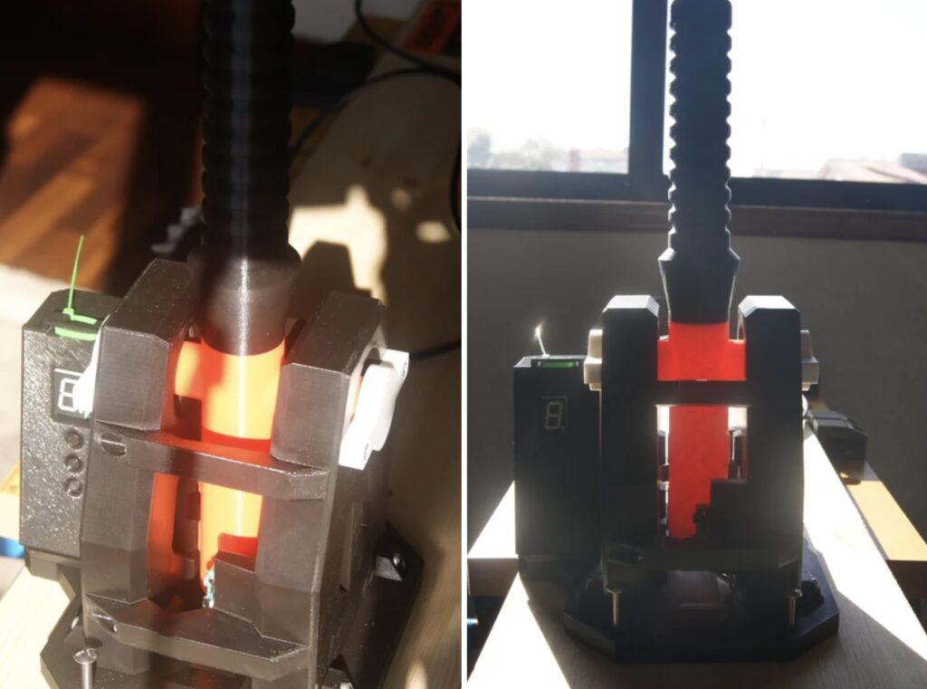
A sequential transmission is one that only allows you to move up or down by a single gear at a time. They’ve always been the norm for motorcycles, because they’re lightweight and compact. And Formula One cars have sequential transmissions for the same reasons. But unlike motorcycles, which require manual shifting, Formula One cars have lightning-fast electronic systems. To recreate that for racing sims, Carlos Almeida designed this sequential gear shift controller.
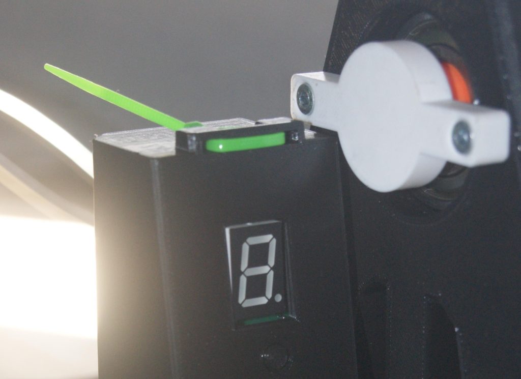
Real Formula One cars have paddle shifters, so that drivers can shift while keeping their hands on their steering wheels. This is a little bit different and looks more like a conventional shifter at first glance. It is a large lever that the user can push forward to move up a gear, or pull back to move down a gear. A seven-segment display shows the current gear number.
Most of the mechanical components are 3D-printable and an Arduino MKR1000 WiFi board is the primary component. Moving the shift lever pushes a switch, which the Arduino registers. Almeida developed the sketch using PlatformIO. It sets the Arduino up as a standard USB HID that will work with any racing sim or game, because it sends key presses like any keyboard or gamepad. It doesn’t receive feedback from the PC, so it has to keep track of the current gear and let the user set the number of gears available using small buttons below the readout display.
If you want a physical sequential shifter for racing sims, this will make a great weekend project.
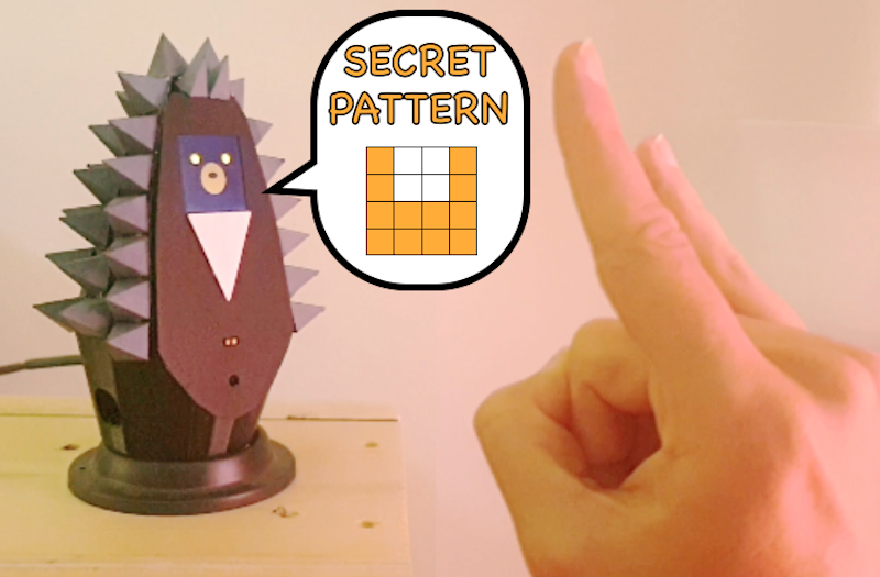
Detecting shapes and gestures has traditionally been performed by camera systems due to their large arrays of pixels. However, Jean Peradel has come up with a method that uses cheap time-of-flight (ToF) sensors to sense both objects and movement over time. Better yet, his entire project is housed within a 3D-printed “Grumpy Hedgehog” that contains not only the sensors, but a highly-interactive 1.44” LCD screen as well.
The goal with this project was to create a smart home companion, which is capable of sensing several different kinds of movements and patterns to perform a wide variety of actions such as sending keystrokes to a PC, controlling a light, or moving a servo motor. This is accomplished by taking VL53L1X ToF modules, which have a 16×16 scanning array and communicate over the I2C bus. Once the attached Arduino MKR WiFi 1010 has read this data, it can determine if the object (which appears closer on the grid) has moved up, down, left, or right.
In order to make this project a bit more friendly, Peradel designed a small enclosure/stand that houses the VL53L1X near the base. Near the top is a small LCD which shows animated hedgehog faces, the “sensor’s view” of the object, and the associated action being taken.
You can read more about the Grumpy Hedgehog gesture sensor here on Hackaday.io.
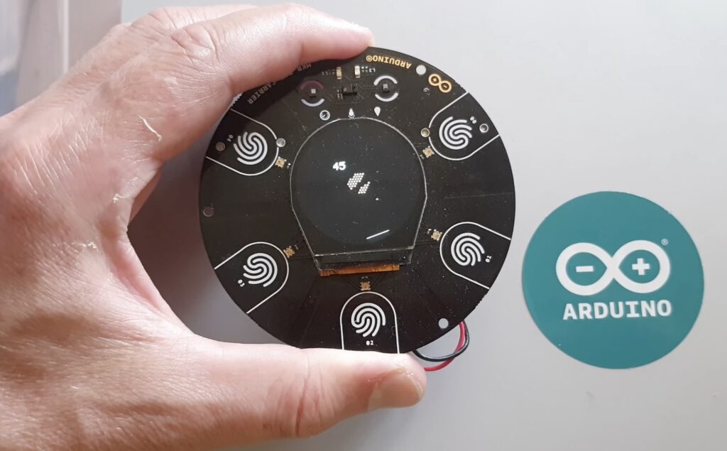
One of the first things many makers try to do when they receive a new piece of cool hardware is write a game for it. This is exactly what Johan Halmén did with his Breakout console that uses the Arduino MKR IoT Carrier board and an MKR1000 to both run and display the game.
Breakout typically involves moving a paddle horizontally along the bottom of the screen to bounce a ball that can destroy the bricks above it. However, since the carrier board’s color OLED screen is circular, Halmén had to create a different version of this, which he calls “BreakIn.” His game features a bunch of hexagonal tiles in the middle and a paddle that moves around the outside that is controlled by the onboard accelerometer. This lets the player tilt the device to move their paddle quickly and accurately.
Getting the circular display to work was a bit more of a challenge than a normal square one because coordinates had to be mapped using a bit of trigonometry first. Additionally, figuring out the angle of tilt and the collision geometry took some math as well. But once everything was up and working, the game was very fun to play, as can be seen in Halmén’s demo video below.
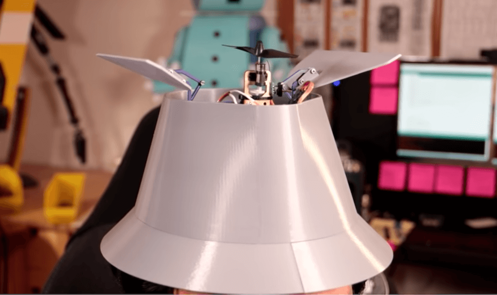
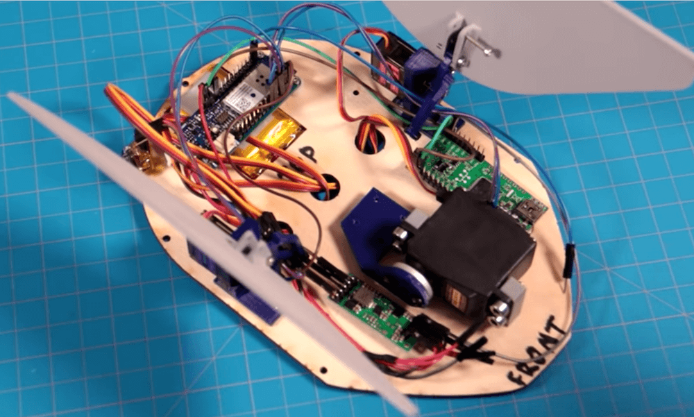
If you ever watched the 1980s Inspector Gadget cartoon, you undoubtedly wanted a hat like his, which can pop out all kinds of useful tools under voice control. Although it won’t allow you to fly off after saying “go go gadget ‘copter,” DJ Harrigan’s replica does produce a spinning propeller and an emergency light with 16 RGB LEDs.
Underneath this 3D-printed hat is a pair of micro servos, with linkage systems that open the top flaps. A standard servo extends the actual gadget. Controlling the device is a MKR1000, and voice commands are registered via a MikroElektronika SpeakUp click board.
While many characters sparked DJ’s imagination for invention and quest for technical skills, one of the earliest was everyone’s favorite 1980’s cyborg policeman: RoboCop, er uh Inspector Gadget! While Inspector Gadget’s gadgets certainly obeyed the laws of cartoon physics rather than real physics, they’re just beyond the edge of plausibility. So in a year long preparation for Halloween 2021, DJ is setting out to make a voice activated hat that can summon real gadgets from his head. No plastic surgery necessary. Some assembly required.
When we see RGB LEDs used in a project, they’re often used more for aesthetic purposes than as a practical source of light. It’s an easy way to throw some color around, but certainly not the sort of thing you’d try to light up anything larger than a desk with. Apparently nobody explained the rules to [Brian Harms] before he built Light[s]well.
Believe it or not, this supersized light installation doesn’t use any exotic hardware you aren’t already familiar with. Fundamentally, what we’re looking at is a WiFi enabled Arduino MKR1000 driving strips of NeoPixel LEDs. It’s just on a far larger scale than we’re used to, with a massive 4 x 8 aluminum extrusion frame suspended over the living room.
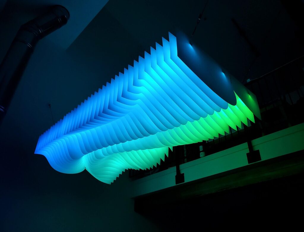
Onto that frame, [Brian] has mounted an undulating diffuser made of 74 pieces of laser-cut cardstock. Invoking ideas of waves or clouds, the light looks like its of natural or even biological origin while at the same time having a distinctively otherworldly quality to it.
The effect is even more pronounced when the RGB LEDs kick in, thanks to the smooth transitions between colors. In the video after the break, you can see Light[s]well work its way from bright white to an animated rainbow. As an added touch, he added Alexa voice control through Arduino’s IoT Cloud service.
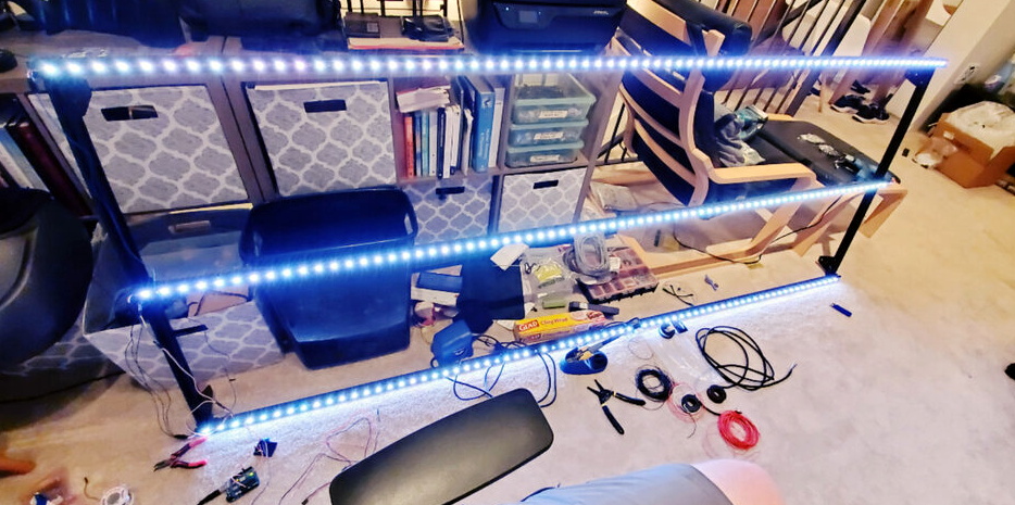
Designed by Brian Harms of NSTRMNT, Light[s]well is a beautifully crafted 4’x8′ light installation for a triple-height living room that’s voice-responsive thanks to the Arduino Alexa skill.
Light[s]well is constructed out of 80/20 extrusions and fasteners, with individually addressable LED strips embedded in the channels of the structure. 74 sheets of laser-cut cardstock make up the undulating light-diffusing wave pattern.
According to Harms, 30 LEDs per meter strips were used to give each gap in the cardstock two LEDs per structural metal beam, for a total of six LEDs per gap. The LEDs are controlled by a MKR1000 (via a logic level shifter) along with the Arduino IoT Cloud.
The COVID-19 pandemic has changed the way we interact with people, things, and the world around us. We’re calling on the community to use an Arduino Nano or MKR board to build solutions that can help us practice better social distancing, improve queue management, or enable touch-free technologies.
Stepping out from our homes, to go to schools, factories, offices and pursue leisure pastimes all these will need to change as lockdown restrictions are eased. With terms like social distancing, remote learning and remote working becoming the norm, let’s see how your ideas can help the world move forward and rebuild everyday life based on a project in one of these two categories.
Category 1: Touch-Free
Create a solution that can be applied to devices that currently rely upon manually pushing a button e.g. elevators, pedestrian crossings, door entry systems, sanitizer dispensers, etc.
Category 2: Social Distance Enablement and Tracking
Create a solution that will allow individuals to maintain the recommended distance apart (1m to 2m) to safely work in the office, factory, commute to work on public transport, or socially interact in cafes and parks. The time people spend within close proximity to each other may also be a factor considered within the design.
N.B. The purpose of the competition is to create products and solutions that are ready to help people around the world to move forward with their lives and safely emerge from lockdown restrictions, rather than developing medical devices.
Contest Scope and Schedule
As any potential solution may be required to operate in a variety of environments, important factors to consider as part of the design process are reliability, durability, connectivity, and power management — hence the option to base your project on any Arduino Nano or MKR board.
The Arduino MKR Family represents the ideal solution for emerging battery powered IoT edge applications. All of the MKR boards share a common pinout for developers to easily shift between wireless communication protocols with minimal software changes, and in a cost efficient manner.
The Arduino Nano Family offers a tiny format, powerful processors and excellent reliability. All of the Nano boards can run embedded machine learning (AI).
Phase 2: Submit your project — Deadline July 14th, 2020: Submit your project for a chance to win up to $10,000 worth of prizes!
Prizes
We are giving away tens of thousands of dollars in prizes to the top five projects, including product assessment and marketing support to bring your project to market! Our judges are going to pick the best qualifying projects based on the judging criteria outlined in the rules section.
Grand Prize
$5,000 voucher for hardware on the Newark online store $750 of pre-manufacturing assessment with Dragon Innovation $5,000 towards product marketing with Hackster.io
Touch-Free
1st Place — Touch-Free
$1,500 voucher for hardware on the Newark online store $750 of pre-manufacturing assessment with Dragon Innovation $3,000 towards product marketing with Hackster.io
2nd Place — Touch-Free
$500 voucher for hardware on the Newark online store $750 of pre-manufacturing assessment with Dragon Innovation $2,000 towards product marketing with Hackster.io
Social Distance Enablement & Tracking
1st Place — Social Distance Enablement & Tracking
$1,500 voucher for hardware on the Newark online store $750 of pre-manufacturing assessment with Dragon Innovation $3,000 towards product marketing with Hackster.io
2nd Place — Social Distance Enablement & Tracking
$500 voucher for hardware on the Newark online store $750 of pre-manufacturing assessment with Dragon Innovation $2,000 towards product marketing with Hackster.io
This is a guest post from Surrogate, a team of developers building games that people play in real-life over the internet.
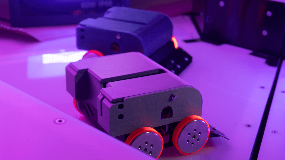
We introduced this concept last year, and have launched three games so far. Our final game of 2019 was SumoBots Battle Royale — where players from anywhere in the world can fight real robots in a battle royale-style arena. The aim of the project was to have the game run semi-autonomously, meaning that the bots could self-reset in between the games, and the arena could run by itself with no human interaction. This was our most complex project to date, and we wanted to share some parts of the build process in more detail, specifically, how we’ve built these robots and hooked them online for people to control remotely.
Robot selection
We’ve started our process by choosing which robots we’d want to use for the game. There were a couple of requirements for the robots when making the evaluation:
Are able to withstand 24/7 collision
Easily modifiable and fixable
Can rotate on the same spot
Must have enough space to fit the electronics
After looking at a lot of different consumer robots, maker projects, and competitive fighting bots, we’ve decided to use the JSUMO BB1 robots for this game. We liked the fact that these bots have a metal casing which makes them very durable, all parts are easily replaceable and can be bought separately, and it has 4 independent motors (motor shields included), one for each wheel, which allows it to rotate on the same spot.
We were pretty skeptical of being able to fit all the electronics into the original casing, but we decided to go with this robot anyways, as it had the best overall characteristics. As this robot is easily modifiable, we can always 3D print an extra casing to fit all the parts.
What is the board?
Now that we’ve decided on the robot, it was the time to define what electronics should we use in this build. As usual, it all starts with the requirements. Here’s what we need for the game to run smoothly:
The robot should be able to recover from any position
Can stay online while charging
Supports WiFi network connection and offers reliable connectivity
Easily programmable and supports OTA updates
Can control four motors simultaneously
Based on these requirements we had the following electronics layout in mind:
We had to find a board that is energy efficient, can send commands to motors, supports parallel charging and has a small footprint on the robot size. With so many requirements, finding the perfect board can be a challenge.
Arduino to the rescue
Fortunately, Arduino was there to help us out. They offer a rich selection of boards to fit every possible robotics project out there and have very detailed documentation for each of the boards.
More importantly, Arduino is known for its high quality, something that is crucial for semi-autonomous types of applications. Coming from an embedded software background and having to work with all sorts of hardware, we often see that some features or board functionalities are not fully finished which can lead to all sorts of unpleasant situations.
After looking at the Arduino’s collection of boards we quickly found a perfect candidate for our project, the Arduino MKR1000 WiFi. This board fits all of our main requirements for the motor controls, is easily programmable via Arduino IDE, and due to its low power design is extremely power efficient, allowing us to have a lower capacity battery. Additionally, it has a separate WiFi chip onboard, which solely focuses on providing a reliable WiFi connection, something that is very important in our use case.
Now that we’ve decided on the “brain” of our robot, it was time to choose the rest of the components.
Robust hardware means working software
Something to keep in mind is that when working with hardware, you should always try to avoid any possible risks. This means that you should always over-do your minimal hardware requirements where possible. The reason is — if your hardware doesn’t work as intended, your whole software stack becomes unusable too. Always chose reliable hardware components for mission-critical applications.
Some of our electric components might look a bit overkill, but due to the nature of our projects, they are a critical requirement.
Avoiding the battery explosions
As there is a lot of robot collision involved in the game, we decided to go with a high safety standard battery solution. After evaluating multiple options on the market, we decided to go with the RRC2040 from RRC (Germany). It has a capacity of 2950 mAh that allows us to run the robots for up to five hours on a single charge. It has an internal circuitry for power management, protection features and it supports SMBUS communications (almost like I2C), and is certified for all of the consumer electronics battery standards. For charging, we used RRC’s charging solution designed specifically for this battery and that offers the possibility to feed power to the application while the battery is being charged.
Note: the Arduino MKR1000 has a pretty neat charging solution on the board itself. You can connect the battery to the board directly as the main power source, and you charge it directly through the MKR1000’s micro USB port. We really wanted to use it to save space and have a more robust design, but due to the large capacity of our battery, we couldn’t use it at full potential. In our future projects with smaller scale robots, we definitely plan to use the board’s internal charging system, as it works perfectly for 700-1800 mAh power packs.
Bot recovery
For the bot to be able to recover from falling on its head, we’ve implemented a flipping servo. We didn’t want to have any risk of not enough torque, so we went with DS3218, which is capable of lifting up to 20KG of weight. Here’s how it works:
Hooking everything together
Now that we’ve decided on all of the crucial elements of this setup, it was time to connect all the elements together. As the first step, we figured what would be the best step way to locate all the pieces within the bot. We then 3D-printed a casing to protect the electronics. With all of the preliminary steps completed, we’ve wired all of the components together and mounted them inside of the casing. Here’s how it looks:
It was really convenient for us that all the pins on the board could be connected just by plugging them in, this avoids a lot of time spent on soldering the cables for 12 robots and more importantly, allowed us to cut out the risk of bad soldering that usually can’t be easily identified.
Arduino = Quick code
Arduino MKR1000 offered us the connectivity we needed for the project. Each sumo robot hosts their own UDP server using MKR1000 WiFi libraries to receive their control commands for a central control PC and broadcasting their battery charge status. The user commands are translated to three different PWM signals using Arduino Servo library for the flipping, left and right side motor controllers. The board used has support for hardware PWM output which was useful for us. Overall we managed to keep the whole Arduino code in a few hundred lines of code due to the availability of Servo and Wifi libraries.
The out of the box ArduinoOTA support for updating the code over the WiFi came in handy during the development phase, but also anytime we update the firmware for multiple robots at the same time. No need to open the covers and attach a USB cable! We created a simple Bash script using the OTA update tool bundled in Arduino IDE to send firmware updates to every robot at the same time.
To summarize
It’s pretty amazing that we live in the age where you can use a mass market, small form factor board like the Arduino MKR1000 and have so much functionality. We’ve had a great experience developing our SumoBots Battle Royale game using the board. It made the whole process very smooth and streamlined, the documentation was right on point, and we never had to hit a bottleneck where the hardware wouldn’t work as expected.
More importantly, the boards have proven to be very robust throughout the time. These SumoBots have been used for more than 3,000 games already, and we haven’t seen a single failure from the MKR1000. For a game where you literally slam the robots in to each other at a high speed, that’s pretty impressive to say the least.
We look forward to working with Arduino on our future games, and we can’t wait to see what they will be announcing in 2020!
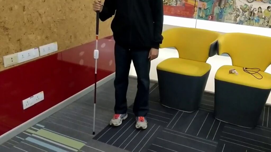
Smartphones have become a part of our day-to-day lives, but for those with visual impairments, accessing one can be a challenge. This can be especially difficult if one is using a cane that must be put aside in order to interact with a phone.
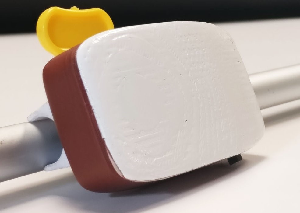
The GesturePod offers another interface alternative that actually attaches to the cane itself. This small unit is controlled by a MKR1000 and uses an IMU to sense hand gestures applied to the cane.
If a user, for instance, taps twice on the ground, a corresponding request is sent to the phone over Bluetooth, causing it to output the time audibly. Five gestures are currently proposed, which could expanded upon or modified for different functionality as needed.
People using white canes for navigation find it challenging to concurrently access devices such as smartphones. Build ing on prior research on abandonment of specialized devices, we explore a new touch free mode of interaction wherein a person with visual impairment can perform gestures on their existing white cane to trigger tasks on their smartphone. We present GesturePod, an easy-to-integrate device that clips on to any white cane, and detects gestures performed with the cane. With GesturePod, a user can perform common tasks on their smartphone without touch or even removing the phone from their pocket or bag. We discuss the challenges in build ing the device and our design choices. We propose a novel, efficient machine learning pipeline to train and deploy the gesture recognition model. Our in-lab study shows that Ges turePod achieves 92% gesture recognition accuracy and can help perform common smartphone tasks faster. Our in-wild study suggests that GesturePod is a promising tool to im prove smartphone access for people with VI, especially in constrained outdoor scenarios.
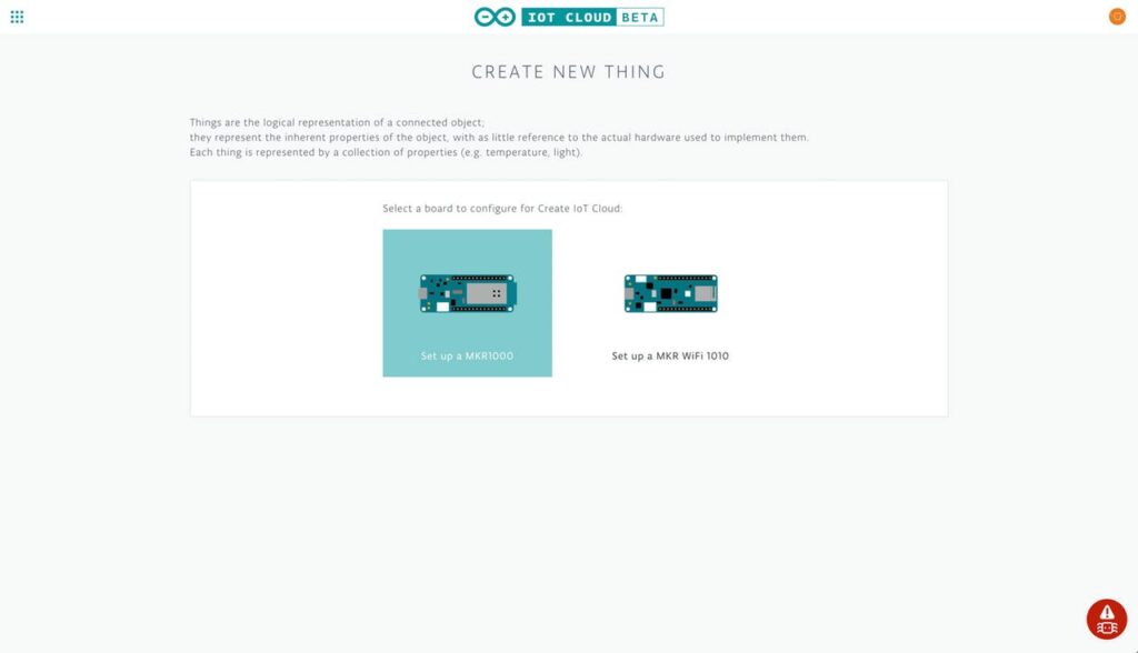
As previously announced, the Arduino IoT Cloud is an easy to use Internet of Things application platform that enables developers to go from unboxing their board to a working device in just minutes.
To help you get started, we’ve put together a quick project that’ll walk you through connecting a MKR1000 (or MKR WiFi 1010) to the Arduino IoT Cloud.
By the end of the tutorial, you’ll be able to control and monitor your board over the Internet using the Arduino IoT Cloud site.
First, we’ll add the board to the Arduino IoT Cloud as a Thing — a representation of the board in the cloud. We’ll then give the Thing a set of Properties which represent sensors, LEDs, motors, and many other components in the project that you’ll want to access from the cloud.
Planet Arduino is, or at the moment is wishing to become, an aggregation of public weblogs from around the world written by people who develop, play, think on Arduino platform and his son. The opinions expressed in those weblogs and hence this aggregation are those of the original authors. Entries on this page are owned by their authors. We do not edit, endorse or vouch for the contents of individual posts. For more information about Arduino please visit www.arduino.cc
You are currently browsing the archives for the MKR1000 category.