Posts | Comments

Planet Arduino

Archive for the ‘lidar’ Category

The rapid rise of edge AI capabilities on embedded targets has proven that relatively low-resource microcontrollers are capable of some incredible things. And with the recent release of the Arduino UNO R4 with its Renesas RA4M1 processor, the ceiling has gotten even higher as YouTuber and maker Nikodem Bartnik has demonstrated with his lidar-equipped mobile robot.

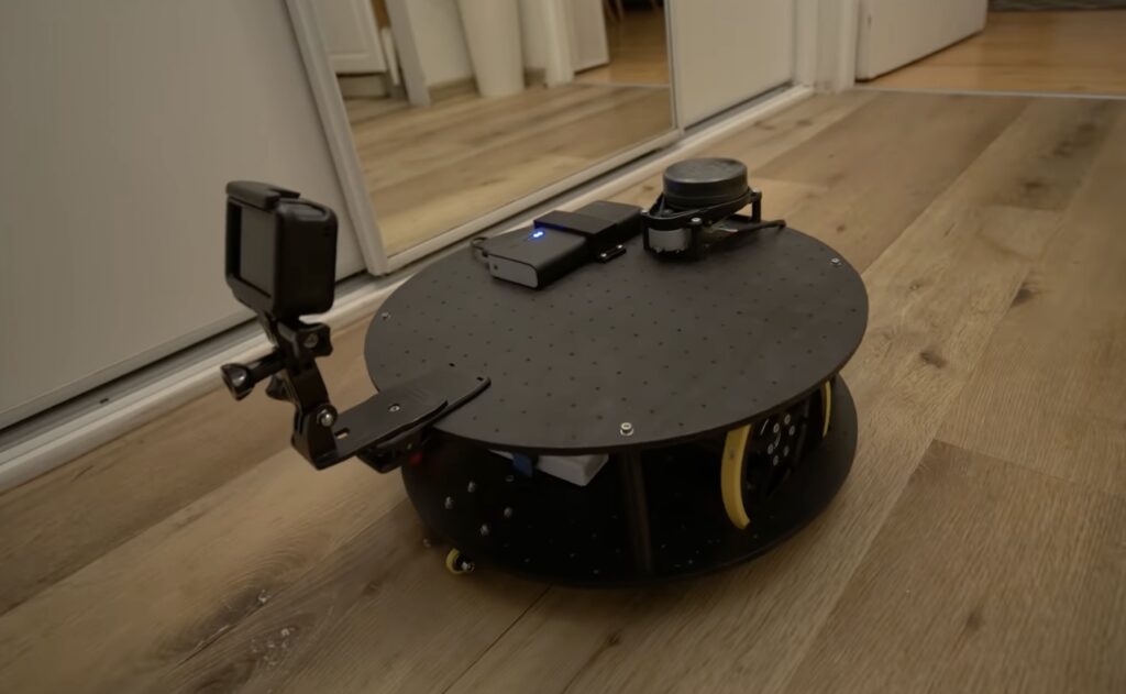
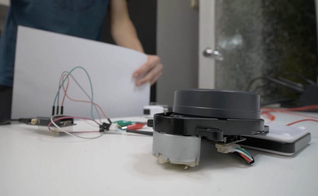
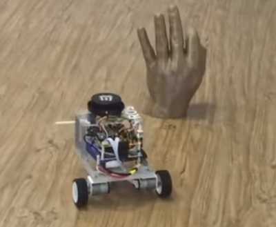
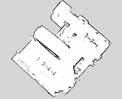
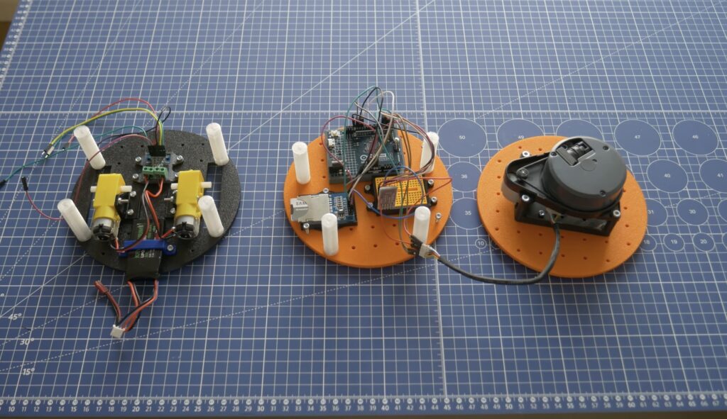
Bartnik’s project started with a simple question of whether it’s possible to teach a basic robot how to navigate around obstacles using only lidar instead of the more resource-intensive computer vision techniques employed by most other platforms. The chassis and hardware, including two DC motors, an UNO R4 Minima, a Bluetooth® module, and SD card, were constructed according to Open Robotic Platform (ORP) rules so that others can easily replicate and extend its functionality. After driving through a series of courses in order to collect a point cloud from the spinning lidar sensor, Bartnik imported the data and performed a few transformations to greatly minify the classification model.

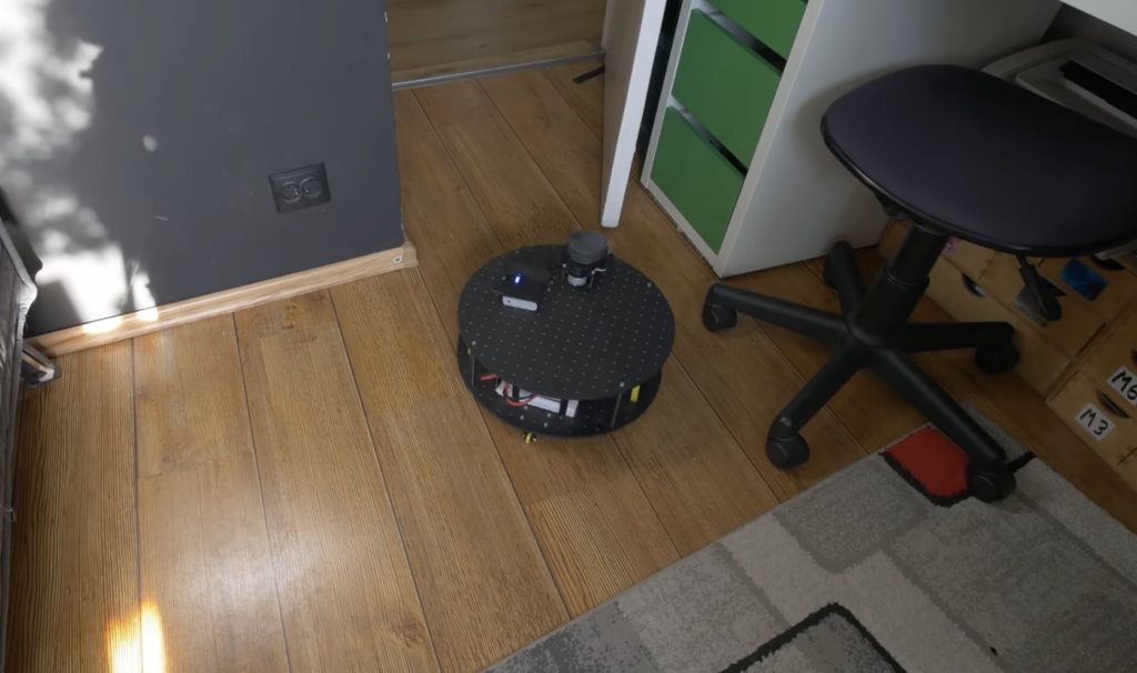
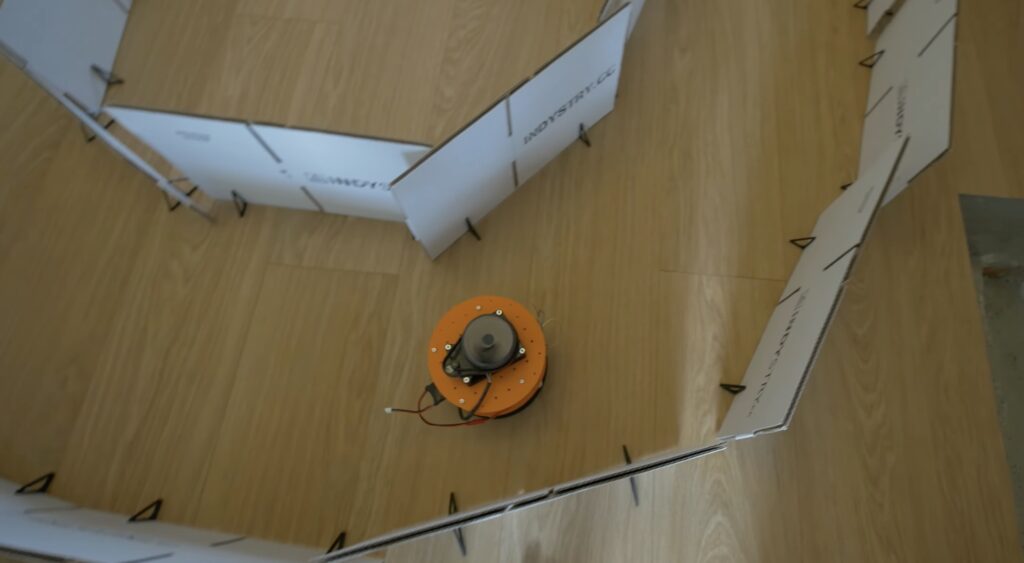
Once trained, the model was exported with help from the micromlgen Python package and loaded onto the UNO R4. The setup enables the incoming lidar data to be classified as the direction in which the robot should travel, and according to Bartnik’s experiments, this approach worked surprisingly well. Initially, there were a few issues when navigating corners and traveling through a figure eight track, but additional training data solved it and allowed the vehicle to overcome a completely novel course at maximum speed.

The post Teaching an Arduino UNO R4-powered robot to navigate obstacles autonomously appeared first on Arduino Blog.

As part of his ongoing autonomous robot project, YouTuber Nikodem Bartnik wanted to add LIDAR mapping/navigation functionality so that his device could see the world in much greater resolution and actively avoid obstacles. In short, LIDAR works by sending out short pulses of invisible light and measuring how much time it takes for the beam to reflect off an object and return to its detector. By combining this distance value with the angle of the sensor at the moment of measurement, a virtual cloud of points can be built and used to represent the entire space around the robot.

The LIDAR module Bartnik opted to use was fairly simple, as it sent measurements in frames over UART that encoded everything including the sensor’s angle, the distance, and the speed of the device. He then created a simple sketch for the MKR WiFi 1010 that takes advantage of the increased power and connectivity to read values and send them to a host machine for further processing and visualization. 

The resulting Python script opens a websocket, which receives the aforementioned data, does some basic filtering, and then displays it within a point-cloud. It also determines the direction in which the robot should move and sends that command back to the MKR board so it can tell the attached Arduino Uno how to move the motors. 

The post See how Nikodem Bartnik integrated LIDAR room mapping into his DIY robotics platform appeared first on Arduino Blog.

LiDAR (or “light detection and ranging”) sensors are all the rage these days, from their potential uses in autonomous vehicles, to their implementation on the iPhone 12. As cool as they are, these (traditionally) spinning sensors tend to be quite expensive, well out of reach for most amateur experimenters. Daniel Hingston, however, has managed to build his own unit for under $40, using an Arduino Uno and a pair of VL53L0X time-of-flight (ToF) sensors.

The lighthouse employs a small gearmotor to rotate the two sensors on top of its cylindrical 3D-printed housing, passing signals to the Arduino via a slip ring. Data can then be visualized using a Processing sketch running on a nearby computer.

As seen at around the 10:00 mark in the video, the setup has been utilized to map out different test enclosures, and could be excellent for use in small robotic applications. More details can be found in Hingston’s tutorial here.

A lighthouse beams light out to make itself and its shoreline visible. [Daniel’s] lighthouse has the opposite function, using lasers to map out the area around itself. Using an Arduino and a ToF sensor, the concept is relatively simple. However, connecting to something that rotates 360 degrees is always a challenge.

The lighthouse is inexpensive — about $40 — and small. Small enough, in fact, to mount on top of a robot, which would give you great situational awareness on a robot big enough to support it. You can see the device in action in the video below.

This lighthouse uses a common solution to the rotating connection problem: a slip ring. While these are mechanical, commercial units can be relatively reliable. To route all the signals, the slip ring needs six wire capsules meaning there are six wires that logically pass through the rotating part. The drive motor spins at 60 RPM, but there are two sensors 180 degrees apart to double the scanning rate. The 3D printed housing uses PLA and looks great.

Of course, the real trick will be using all this data meaningfully in your robot or whatever is listening to the lighthouse. That, however, is a different topic. If you think two ToF sensors are good, why not try three?


Dolphins are not only amazing swimmers and extremely intelligent, but can also observe their surroundings using echolocation. While extremely useful in murky water, Andrew Thaler decided to make a device that would enable him to him observe his (normally dry) surroundings with a similar distance-indicating audio setup.

While he first considered using an ultrasonic sensor, he eventually settled on LiDAR for its increased range, and uses an Arduino to translate distance into a series of audio clicks. Sound is transferred to Thaler through bone conduction speakers, mimicking the way dolphins hear without external ears. 

He notes that while using the “DolphinView” headset is initially disorienting, he was eventually able correlate his surroundings with the system’s audio feedback. Arduino code and parts list is available on GitHub, and the mechanical frame design can be found on Thingiverse if you’d like to build your own!

On July 20th, 1969 man first set foot on the moon with the Apollo 11 mission, or so they say. If it was faked, or so the theory goes, one would think that there were a few details that don’t quite add up. One such theory is that the hatch on the lunar module isn’t actually large enough to allow a fully-suited up astronaut to enter and exit the module.

Rather than make assumptions, astrophotographer and hacker “AstronomyLive” took matters into his own hands and used a homemade LIDAR unit to measure the hatch of Lunar Module #9 at the Kennedy Space Center, as well as an Apollo spacesuit.

The Arduino-powered device aims the laser, and transmits this information to a tablet that also provides a convenient user interface. This data was then arranged as a point cloud, proving that… You can take a guess, or watch the video below to see his conclusion!

I used the Garmin LIDAR-Lite V3 along with a couple of metal geared servo motors to build a simple pan/tilt scanner, which pairs via Bluetooth to an Android app I built using MIT App Inventor 2 to control and receive data from the Arduino. It’s simple but effective. Although every tutorial I read suggested I couldn’t safely pull the voltage off the board for the motors, but I found that the vin pin gave me no problems, as long as I used a 5V 1.5A linear voltage regulator between the pin and the motors. I supplied 9V using AA batteries to the power jack on the Arduino. In the future I may upgrade the scanner by adding a small camera to grab RGB data for each point as it samples, and ideally I would change the whole thing to use a stepper motor for continuous spinning and scanning to generate a denser cloud.

What’s the best way to image a room? A picture? Hah — don’t be so old-fashioned! You want a LIDAR rig to scan the space and reconstruct it as a 3D point map in your computer.

Hot on the heels of [Saulius Lukse]’s scanning thermometer, he’s replaced the thermal camera on their pan/tilt setup with a time-of-flight (TOF) camera — a Garmin LIDAR — capable of 500 samples per second and end up scanning their room in a mere fifteen minutes. Position data is combined with the ranging information to produce a point cloud using Python. Open that file in a 3D manipulation program and you’ll be treated to a sight like this:

That’s an image generated of a 4.7 million point cloud. It’s not perfect, but it’ll certainly do.

[Lukse] laments that the camera requires ideal lighting conditions that make it unsuitable to for a lot of outdoor imaging and is similarly limited to shorter ranges. It also necessitates hauling a laptop around so he’s considering making it an all-in-one package down the road.

Want to more about how LIDAR works? Check out this teardown video of a police speed enforcement LIDAR ‘gun.’ Or have a look at this (faster) completely DIY laser scanner.


Filed under: Arduino Hacks, laser hacks

The Robot Operating System (ROS) is typically associated with big robots but [Grassjelly] decided to prove differently by creating Linorobot. This small, differential drive robot is similar in appearance to many small Arduino based robots often used for line following. Linorobot packs a lot more computing power with a Teensy 3.1 connected to a Radxa Rock Pro. The Teensy handles the motors, reading their encoders, and acquisition of IMU data.

The Radxa, new to us here at Hackaday, is a single board computer based on the quad-core ARM Cortex-A9 1.6 GHz CPU. It may not have been seen on our pages but if you’re at Hackaday Belgrade you can attend a session on building a cluster using it. The ability to run Linux is key to using ROS, which is an open source system for controlling robots. With the Radxa running ROS it interfaces directly to the Neato XV-11 Lidar’s dedicated controller board.

Avoiding the hand. Mapping with lidar.

The Linorobot packs into a small robot the capabilities usually seen in much larger and expensive robots such as the Turtlebot 2. With this diminutive robot hackers can learn about doing SLAM (Simultaneous Localization and Mapping) and autonomous navigation, plus the other capabilities of ROS.

[Grassjelly] has a tutorial on building the robot which is also a good introduce to ROS. He provides the software as open source. It’s an impressive project which provides a small, comparatively affordable robot for learning and working with ROS. A video of Linorobot SLAMing and navigating [Grassjelly’s] lab is after the break.


Filed under: Arduino Hacks, robots hacks


  • Newsletter

    Sign up for the PlanetArduino Newsletter, which delivers the most popular articles via e-mail to your inbox every week. Just fill in the information below and submit.

  • Like Us on Facebook