How far would you go for your cup of tea? [samsungite]’s missus doesn’t like clutter on her countertops, so away the one-cup kettle would go back into the cupboard for next time while the tea steeped. As long as there’s room for it in there, why not install it there permanently? That’s the idea behind RoboTray, which would only be cooler if it could be plumbed somehow.
RoboTray went through a few iterations, most importantly the switch from 6mm MDF to 4 mm aluminum plate. A transformer acts as a current sensor, and when the kettle is powered on, the tray first advances forward 7 cm using a 12 VDC motor and an Arduino. Then it pivots 90° on a lazy Susan driven by another 12 VDC motor. The kettle is smart enough to turn itself off when finished, and the Arduino senses this and reverses all the steps after a ten-second warning period. Check it out in action after the break.
If [samsungite] has any more Arduinos lying around, he might appreciate this tea inventory tracker.
Traditionally, the useless machine is a simple one that invites passersby to switch it on. When they do, the machine somehow, some way, turns itself off; usually with a finger or finger-like object that comes out from the box in what feels like an annoyed fashion. Honestly, that’s probably part of what drives people to turn them on over and over again.
What’s really happening is that an Arduino is getting a signal from the toggle switch, and is then rotating it on a ball bearing with a stepper motor driven through an H-bridge.
It shouldn’t be too hard to make one of these yourself, given that [Bart] has provided the schematic and STLs. If we weren’t living in such touchy times, we might suggest building one of these into your Halloween candy distribution scheme somehow. Sell the switch as one that turns on a candy dispenser, and then actually dispense it after three or five tries.
I have a good background working with high voltage, which for me means over 10,000 volts, but I have many gaps when it comes to the lower voltage realm in which RC control boards and H-bridges live. When working on my first real robot, a BB-8 droid, I stumbled when designing a board to convert varying polarities from an RC receiver board into positive voltages only for an Arduino.
Today’s question is, how do you convert a negative voltage into a positive one?
In the end I came up with something that works, but I’m sure there’s a more elegant solution, and perhaps an obvious one to those more skilled in this low voltage realm. What follows is my journey to come up with this board. What I have works, but it still nibbles at my brain and I’d love to see the Hackaday community’s skill and experience applied to this simple yet perplexing design challenge.
The Problem
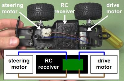
RC toy truck and circuit with no common
I have an RC receiver that I’ve taken from a toy truck. When it was in the truck, it controlled two DC motors: one for driving backwards and forwards, and the other for steering left and right. That means the motors are told to rotate either clockwise or counterclockwise as needed. To make a DC motor rotate in one direction you connect the two wires one way, and to make it rotate in the other direction you reverse the two wires, or you reverse the polarity. None of the output wires are common inside the RC receiver, something I discovered the hard way as you’ll see below.
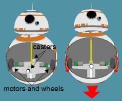
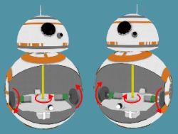
I wasn’t using the RC receiver with the toy truck. I extracted it from the truck and was using it to control my BB-8 droid. My BB-8 droid has two motors configured as what in the BB-8 builders world is called a hamster drive, though is more widely known as a tank drive or differential drive (see the illustrations). Rotate both wheels in the same direction with respect to the droid and the droid moves in that direction. Reverse both wheels and it drives in the opposite direction. Make the wheels rotate in opposite directions and it turns on the spot.
The big picture – RC to drill motors
The motors in my BB-8 are drill motors and are controlled by two H-bridge boards. An Arduino does pulse width modulation to the H-bridge boards for speed control, and controls which direction the motors should turn. Finally, the RC receiver is what tells the Arduino what to do. But a converter board, the subject of this article, is needed between the RC receiver and the Arduino. Note that the Arduino is necessary also for countering when the BB-8 droid wobbles and for synchronizing sounds with the movement, but those aren’t addressed here.
Since there are two motors and two directions for each motor, the RC receiver needs to control four pins on the Arduino to make the two drill motors behave as follows: motor 1/clockwise, motor 1/counterclockwise, motor 2/clockwise, motor 2/counterclockwise. And whatever voltages the receiver puts on those pins has to be relative to the Ardunio’s ground.
And herein lies the problem. The Arduino expects positive voltages with respect to its ground on all those pins. So I needed a way to map the RC receiver’s two sets of motor control wires, which can have either positive or negative voltages across them, to the Arduino pins which only want positive voltages. And remember, none of those RC receiver wires are common inside the receiver.
My Fumbling First Approach
Now, keep in mind, electronics is a general interest of mine and except for what we were taught in high school physics class, I’m self-taught. That means I’ve “read ahead” but much of my knowledge has been determined by what projects I’ve done. So I have gaps in my knowledge. I’d never turned negative voltages into positive before. It sounded simple enough. Searching online didn’t help though. The closest I got was in two old posts in forums where the answers were “It’s easy to do. I can do it with a single resistor.” But there was no further explanation and I didn’t ask my own question anywhere at that point.
Using a transistor
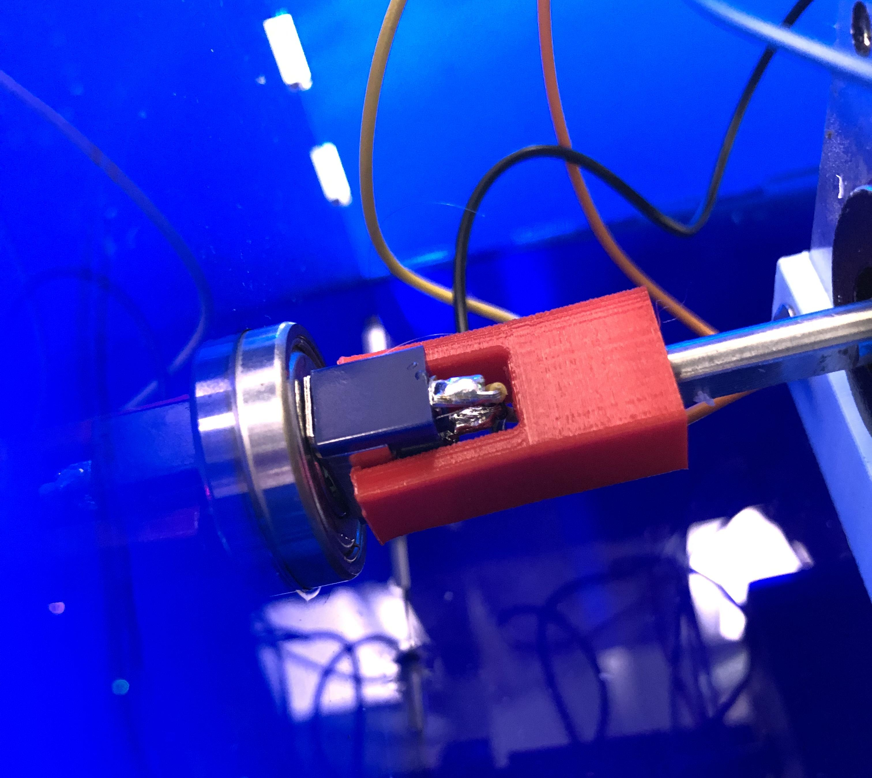
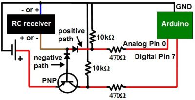
Instead I came up with my own approach with just one set of wires from the RC receiver first. The wires coming from the receiver were blue and brown and could have either polarity depending on which way the receiver is being told to rotate the motor: clockwise or counterclockwise. That meant I needed two diodes to create two possible paths for the different polarities the brown wire could be: positive or negative. I then added a battery for the one path that was negative, to turn it into a positive.
Next, I put a PNP transistor between the positive of the battery and the receiver. With no signal from the RC transmitter, the transistor’s base is negative with respect to the emitter, but not enough to turn the transistor on. That’s because the battery’s negative is connected to the receiver’s blue wire and since there’s no signal from the transmitter, the brown wire is also at the same potential as the blue wire, and with battery negative.
The idea was that when the transmitter sent a signal to make that brown wire negative with respect to the blue wire, it would become even more negative and turn on the PNP transistor. A positive signal would then go from the battery, through the transistor to the Arduino.
The most obvious problem was that the Arduino wanted to see 3 volts to register as a HIGH input, meaning the battery would have to be at least 3 volts and so even with no signal from the transmitter, that would be -3 volts to the transistor, turning it on when it wasn’t supposed to be on.
Using A Relay Instead
Using a relay
And so I immediately thought of using a relay instead. I’d use the current running through the negative path to energize the relay, closing a switch that was completely independent of the RC receiver. The Arduino has a 5V output pin, so I made that switch close a circuit between the 5V pin and the Arduino’s pin 7, giving pin 7 the needed positive voltage.
The 1 in the circle in the schematic shows where I wanted to put a resistor in order to limit the current going through the relay’s coil. However, I tried with resistors all the way down to 4.7 ohms but the coil didn’t have enough current to close the switch. With no resistor, it worked and the current was 70mA. The relay’s coil was rated for 3V/120mA so I left it.
Using a relay did seem very heavy-handed, but it was the only solution I could come up with and I already had the relay in stock.
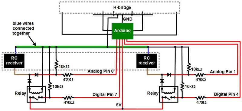
The next step was to add a second relay, doing the same for the second set of wires coming from the RC receiver for the second motor.
No Common In The Receiver
Schematic with common blue RC wires
But the behavior was seemingly sporadic. And keep in mind that there was a whole dual H-bridge circuit that was also connected to the Arduino’s ground. I’d worked with relays a lot before, and the RC receiver came from a commercially made and functional toy so I had no reason to suspect that. On the other hand, I’d made the H-bridge circuit from scratch since I already had most of the parts, and I was new to H-bridges and MOSFETs. So at first I spent a good two weeks of spare time thinking my problem was with the H-bridge and drill motor side. I’m sure we’ve all experienced the same blindness, thinking the most likely culprit is the part you had a hand in.
But at some point I disconnected the H-bridge and tested just the RC receiver circuit, watching the voltages at the Arduino pins while I remotely turned on both “motors” in both directions in all combinations (no motors were connected at the time though). The only odd behavior I saw was when I turned the motors on in opposite directions.
Notice in the schematic that I’d connected together both blue wires coming from the RC receiver. Up to that point I’d been assuming that the blue wires were common inside the receiver and that it was only the brown wires that switched from positive to negative with respect to the blue wires. From the behavior I was seeing it looked like both wires were switching polarity, possibly around some other internal common reference.
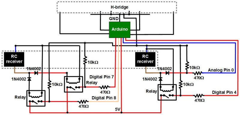
Finished RC-to-Arduino converter schematic
So I added a third relay on one of the positive paths of one of the sets of wires. That meant the corresponding blue wire no longer needed to be grounded, keeping both of the receiver’s blue wires separate. Note that I didn’t bother putting in a fourth relay for the remaining positive path, and it turned out to not be necessary. At that point the circuits worked great and continue to do so.
The Ask
And so I ask, is there a better way to convert the RC receiver output to something the Arduino can use? Relays require power, so it would be nice if there was a solution that didn’t require any extra power. My relay solution seems very early 1900s. Or maybe it’s a good solution after all, but just one of many. Let us know in the comments below.
This project is part 4 in the building a robot arm tutorial. In the first part I show how to design the arm, the second part shows how to design the base, and the third shows how to design the mount. After all of the Computer Aided Drafting (CAD) and 3D modeling […]
Controlling motors with an Arduino is a fun and generally integral part of the learning process for most up-and-coming embedded electronics enthusiasts. Or quite simply, using motors is fun ’cause you can make robots, tanks and stuff that moves. And thanks to Freetronics we have their new HBRIDGE motor shield for Arduino to review, so let’s check it out and get some things moving with it.
Arriving in retail-friendly packaging, the HBRIDGE can be stored with the included reusable packaging, and also has a quick-start guide that explains the technical specifications and URLs for tutorials:
The shield is compatible with the latest R3-series Arduino boards including the Leonardo and of course the Freetronics Eleven board:
Specifications
The HBRIDGE shield is based on the Allegro A4954 Dual Full-Bridge DMOS PWM Motor Driver. For the curious, you can download the data sheet (pdf). This allows very simple control of two DC motors with a maximum rating of 40V at 2A, or one bipolar stepper motor. Unlike other motor shields I’ve seen, the HBRIDGE has a jumper which allows the power supply for the motor shield to be fed into the Arduino’s Vin line – so if your motor power supply is under 12V DC you can also power the Arduino from the same supply. Or you can run the motors from the Arduino’s power supply – if you’re sure that you won’t exceed the current rating. Frankly the former would be a safer and this the preferable solution.
The motor(s) are controlled very simply via PWM and digital logic. You feed the A4954 a PWM signal from a digital output pin for motor speed, and also set two inputs with a combination of high/low to set the motor direction, and also put the motor controlled into coast or brake mode. However don’t panic, it’s really easy.
The chassis is pretty much a standard tank chassis with two DC motors that run from an internal 9V battery pack. Search the Internet for “Dagu Rover 5″ for something similar. Connection is a simple manner of feeding the power lines from the battery and the motor wires into the terminal block on the HBRIDGE shield.
Next, take note of two things. First – the slide switches below the jumpers. Using these you can select the maximum amount of current allowed to flow from the power supply to each motor. These can be handy to ensure your motor doesn’t burn out by drawing too much current in a stall situation, so you can set these to the appropriate setting for your motor – or if you’re happy there won’t be any issues just leave them both on 2A.
The second thing to note is the six jumpers above the switches. These control which digital pins on your Arduino are used to control the motor driver. Each motor channel requires two outputs and one PWM output. If you leave them all on, the Arduino pins used will be the ones listed next to each jumper, otherwise remove the jumpers and manually wire to the required output. For the purposes of our demonstration, we’ll leave all the jumpers in. A final word of warning is to be careful not to touch the A4954 controller IC after some use – it can become really hot … around 160 degrees Celsius. It’s the circled part in the image below:
So back to the DC motors. You have two digital outputs to set, and also a PWM signal to generate – for each channel. If you set the outputs to 1 and 0 - the motor spins in one direction. Use 0 and 1 to spin the other way. And the value of the PWM (0~255) determines the speed. So consider the following sketch:
Instead of chasing the tank chassis with a camera, here it is on the bench:
Now to try out a stepper motor. You can control a bipolar motor with the HBRIDGE shield, and each coil (pole) is connected to a motor channel.
Hint – if you’re looking for a cheap source of stepper motors, check out discarded office equipment such as printers or photocopiers.
For the demonstration, I’ve found a random stepper motor from a second-hand store and wired up each pole to a channel on the HBRIDGE shield – then run the Arduino stepper motor demonstration sketch by Tom Igoe:
/*
 Based on example by Tom Igoe included in Arduino IDE
 at File -> Examples -> Stepper -> stepper_oneRevolution

 Modified to suit pinouts of Freetronics HBridge Shield
*/

#include <Stepper.h>

const int stepsPerRevolution = 240;  // change this to fit the number of steps per revolution
                                     // for your motor

// initialize the stepper library using the default pins on the HBridge Shield:
Stepper myStepper(stepsPerRevolution, 4, 7, 3, 2);

void setup() {
  // set the speed at 200 rpm:
  myStepper.setSpeed(200);
  // initialize the serial port:
  Serial.begin(38400);
}

void loop() {
  // step one revolution  in one direction:
   Serial.println("clockwise");
  myStepper.step(stepsPerRevolution);
  delay(1000);

   // step one revolution in the other direction:
  Serial.println("counterclockwise");
  myStepper.step(-stepsPerRevolution);
  delay(1000);
}
With the following results:
Considering it was a random stepper motor for which we didn’t have the specifications for – it’s always nice to have it work the first time! For more formal situations, ensure your stepper motor matches the power supply voltage and so on. Nevertheless it shows how easy it can be to control something that appears complex to some people, so enjoy experimenting with them if you can.
Competition
Thanks to Freetronics we have a shield to give away to one lucky participant. To enter, clearly print your email address on the back of a postcard and mail it to:
H-Bridge Competition, PO Box 5435 Clayton 3168 Australia.
Entries must be received by the 20th of September 2013. One postcard will then be drawn at random, and the winner will receive one H-Bridge shield delivered by Australia Post standard air mail. One entry per person – duplicates will be destroyed. We’re not responsible for customs or import duties, VAT, GST, import duty, postage delays, non-delivery or whatever walls your country puts up against receiving inbound mail.
Conclusion
As demonstrated, the HBRIDGE shield “just works” – which is what you need when bringing motorised project ideas to life. The ability to limit current flow and also power the host board from the external supply is a great idea, and with the extra prototyping space on the shield you can also add extra circuitry without needing another protoshield. Very well done. For more information and to order, visit the Freetronics website. Full-sized images are on flickr. And if you made it this far – check out my new book “Arduino Workshop” from No Starch Press.
In the meanwhile have fun and keep checking into tronixstuff.com. Why not follow things on twitter, Google+, subscribe for email updates or RSS using the links on the right-hand column? And join our friendly Google Group – dedicated to the projects and related items on this website. Sign up – it’s free, helpful to each other – and we can all learn something.
Note – The motor shield used in this article was a promotional consideration supplied by Freetronics.
How many times have you seen a secret hideout with a secret knock? It’s a staple of cheesy dramas, Saturday afternoon movies, and tree houses throughout the world.
While working on another project I ran across the Arduino knock sensor tutorial. Sensing a single knock is a great little project for learning about microcontrollers, but what about sensing specific knocks? Seeeeecret knocks? And if we could detect a secret knock, shouldn’t it unlock a door? If you can’t tell by looking this was cobbled together from spare stuff around the lab, it’s not much more than a piezo speaker, a tiny gear reduction motor, and an Arduino. And PVC pipe.
**Disclaimer: This was built with stuff I had lying around the lab. How about a video to explain:
A microphone (okay, really a speaker) presses against the door and listens for knocks. If it hears the right number of knocks in the right cadence it triggers the motor to turn the deadbolt and unlock the door. If the sequence isn’t recognized, the system resets and listens for knocks again.
The default code is Shave and a Hair Cut but if that’s too obvious you can enter a new knock sequence by holding down the red button and knocking your new secret knock (up to 20 knocks). The rhythm of your favorite song, Morse code, whatever! The widget will play back your knock (by blinking the lights) so you can be sure it heard everything correctly.
The whole thing is attached to the door with suction cups
The components are simple, most of the work is done in the microcontroller. The source code for the Arduino is available at the bottom of the page if you’re curious.
How does it work?
First it records the time between knocks. If there is a long wait for a knock it stops listening and starts analyzing.
Basic circuity
First it checks the number of knocks. If that’s right, we go on to more vigorous authentication. First it converts the absolute timing of the knocks to the rhythm of the knocks. This lets us knock fast or slow and as long as we get the rhythm right it will unlock. That way I can still unlock the door if I’m tired or full of caffeine. After this it compares the timing with the secret key and if any individual knock is off by too much or the whole thing is off by a certain average amount the door stays locked. If not, we trigger the motor to turn and the lock to unlock. If the programming button is pressed it saves the rhythm information and then plays it back.
The detection is surprisingly accurate and can even be dialed up so it’s precise enough to detect an individual person’s variation on a knock, similar to a Morse coder’s ‘fist‘. (Though when the verifying is this tight it also triggers false negatives which are annoying.)
To keep things simple (and it’s because it’s what I had available) a motor is attached to the deadbolt using two pieces of spring steel bolted across the D shaft of the motor so that the connection will slip when the lock turns as far as it can. A more precise (and probably durable) way to do it would be to use a servo to turn the lock or have a detector sense when the lock had reached its extent. Or replace the dead bolt with a solenoid. Or whatever else you can think of.
Circuit fitting
The rest of the electronics are nothing special. Its so simple that just adding feedback LEDs almost doubled the parts count. The Arduino has a lot of unused potential on this project.
No proper schematic yet, but there’s a layout and parts list at the bottom of the page. Look for a fully documented Instructable soon.
With some extra electronics (an H-bridge) it would be possible to have the door automatically lock as well as unlock. Other improvements or changes that someone could do:
Adding a knob to adjust the sensitivity.
Building it into an actual door knocker.
Using a more economical microcontroller and enabling a sleep mode for better battery life.
Making the whole package small enough to fit inside the door.
Storing several knocks so several people can have their own private knocks.
Adding a real-time clock and using different knocks for different days of the week or times of day.
Listening for door bell presses rather than door knocks.
Adding a servo or solenoid powered knocker to provide feedback through the door. It could then offer a challenge-response security where the door starts a knock sequence and the user has to finish it correctly.
Rather than listening for knocks, putting a photoresistor in the peep hole and detecting flashes of light from a pocket flashlight or simply by placing your hand over the peephole. Or an infrared receiver and use special key presses on a remote control.
Knock sensor layout (click for larger view)
Do I have to point out that this is not a great security measure since overhearing a knock sequence is pretty trivial? No. But it’s fun to make and play with.
Planet Arduino is, or at the moment is wishing to become, an aggregation of public weblogs from around the world written by people who develop, play, think on Arduino platform and his son. The opinions expressed in those weblogs and hence this aggregation are those of the original authors. Entries on this page are owned by their authors. We do not edit, endorse or vouch for the contents of individual posts. For more information about Arduino please visit www.arduino.cc
You are currently browsing the archives for the H-Bridge category.