30
As we work on projects we’re frequently upgrading our tools. That basic soldering iron gives way to one with temperature control. The introductory 3D printer yields to one faster and more capable. One reason for this is we don’t really understand the restrictions of the introductory level tools. Sometimes we realize this directly when the tool fails in a task. Other times we see another hacker using a better tool and realize we must have one!.
The same occurs with software tools. The Arduino IDE is a nice tool for starting out. It is easy to use which is great if you have never previously written software. The libraries and the way it ties nicely into the hardware ecosystem is a boon.
When you start on larger projects, say you upgrade to a Due or Teensy for more code or memory space, the Arduino IDE can hamper your productivity. Moving beyond these limitations requires a new, better tool.
Where do we find a better tool? To begin, recognize, as [Elliot] points out that There is no Arduino “Language”, we’re actually programming in C or C++. We chose which language through the extension on the file, ‘c’ for C and ‘cpp’ for C++. An Arduino support library may be written in C or C++ depending on the developer’s preference. It’s all mix ‘n match.
Potentially any environment that supports C/C++ can replace the Arduino IDE. Unfortunately, this is not easy to do, at least for inexperienced developers, because it means setting up the language tool chain and tools for uploading to the board. A developer with that much experience might eschew an integrated development environment altogether, going directly to using makefiles as [Joshua] describes in Arduino Development; There’s a Makefile for That.
The reality is the Arduino IDE is not much more than a text editor with the ability to invoke the tools needed to compile and download the code to the Arduino. A professional IDE not only handles those details but provides additional capabilities that make the software development process easier.
Eclipse CDT & Arduino Plug-In
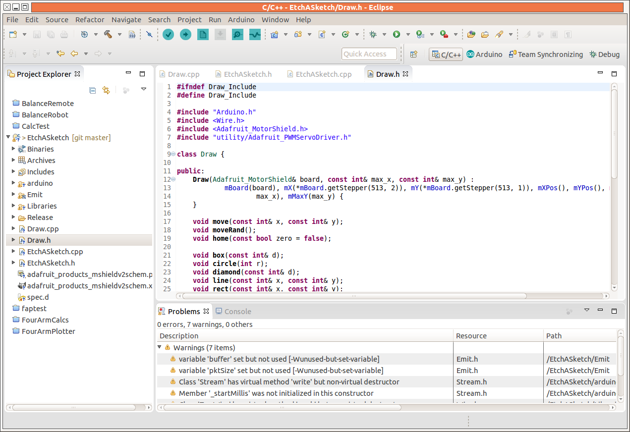
An alternative to the Arduino IDE is Eclipse, a development environment used by professional and hobby developers. It’s open-source software and extensible via plugins. Many developers have contributed to its development, including some with corporate support.
Eclipse based Arduino development uses two additions to the basic Eclipse IDE. One is the C/C++ Development Tooling (CDT). The CDT not only adds the C/C++ development capability but tools for automatic code completion and insertion, and also some code refactoring. Trust me, once you understand how to use these capabilities you’ll miss them dearly when not available.
The other addition is a plug-in developed by [Jantje Baeyens]. The plug-in is free and open-source.
This setup works in combination with the build environment for the Arduino IDE. You still need the IDE installed; you just don’t have to use it.
Earlier this year I installed Eclipse Luna with the plug-in and the Arduino 1.6.0 IDE while running Ubuntu 14.04. I just followed the installation directions on the Eclipse and plug-in sites and it went smoothly. Since then [Jantze] released a version of Eclipse Luna with the latest version of the plug-in pre-installed. I downloaded it and the 1.6.5r5 Arduino IDE recently. It works fine and installing updates for the plug-in is handled automatically by Eclipse.
When making a switch like this you need to know both where the current tool is inadequate, how the new tool addresses those limitations, and what additional benefits will accrue. We’ll address the limitations and how they are addressed first, and then the added benefits.
Arduino IDE Limitations
Editor Tabs
When projects get larger they obviously have more lines of code. Having hundreds or thousands of lines of code in a single file is a nightmare. Scrolling through that large a file to find a single line of code is time consuming. That is why compilers support splitting code into multiple files. Moving between editor windows is far easier than scrolling.
The Arduino IDE supports multiple files by adding more tabs. If you use INO files you’re only adding one at a time, but if you use C/C++ header and source files it’s two at time. With the Arduino IDE all the files have to be in open windows in order to be processed by the compiler. Sooner or later you run out of space across the top of the screen for more tabs.
 My 23″ monitor supports around 18 tabs and my 19″ side monitor about a dozen. Tabs for additional files scroll off to the right. They can be reached using Ctrl-ALT-Right, or through a drop down list on the right, which is cumbersome to use. To add insult, on my Ubuntu system the Ctrl-ALT-Right is used for changing workspaces so cannot be used for changing tabs.
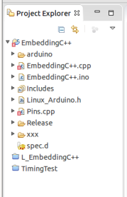
Eclipse also uses tabs but they are only involved with editing. The files for a project are listed in a Project Explorer sub-window. Any file can be opened in the editor and closed when the editing or viewing is done. Having only the files open pertinent to your current activity reduces distractions. Eclipse also allows access to multiple projects to be available at the same time. This is useful if you want to get code snippets for your current project from an older one, or if you are working on two Arduinos that cooperate with one another.
Compilation Speed
The Arduino IDE copies every file to a temporary directory as an early step in the build process. This forces the build environment to see every file as changed, which in turn means the files are all compiled.
Under Eclipse the build does not move the files. The tool chain recognizes that once a file is compiled it does not need to be compiled again until a change is made in the source. In extremely large commercial projects this can literally save hours of time. Even in large hobby projects the time savings can be substantial.
Hunting for Errors
The console at the bottom of the Arduino IDE displays the compilation process and the errors that occur. The errors are listed with the file, line number, and the column of the error:
somefile.cpp:11:3: error: expected '}' before 'else'
To fix the error you need to find the file – ouch! if it’s on the drop down list – and then find the line in the file. This is time consuming.
Eclipse reports errors in two ways. The first is a console window similar to the one for the Arduino. The difference is you can click on an error and be taken to the line of code. Eclipse will even open the file if it’s not currently active in an editor. A real time saver.
The second is a list of errors in a “Problems” window stripped of all the compiler gobbledygook. Reading this list is much quicker than either IDE’s console window. By scanning the list you may see that the reported error is not the error that needs to be fixed. Sometimes errors, typos for example, are reported in multiple locations but the correction is elsewhere. The console window is still important because it provides the additional information that is sometimes needed to understand exactly what is causing the problem.

Terminal Annoyance
An annoyance with the Arduino IDE is the need to shut down the serial port terminal when you want to upload new code. The Eclipse solution manages this while keeping the terminal window open.
Note: This appears to have changed from the 1.60 to the 1.6.5 version of the Arduino IDE. If you are working with an older version and sticking with the Arduino IDE you should upgrade to the latest.
Eclipse Enhancements
Eclipse provides enhancements in addition to the improvements discussed above. Some of these are capabilities you don’t realize you need, but will love once you have them.
 Code completion is a simple enhancement that saves keystrokes and prevents errors by adding closing braces, quotes, brackets, parentheses, etc. This reduces errors due to omissions, and helps keep code better organized. (You do put braces around your if-clauses, don’t you? Apple didn’t, which created a security hole in their SSL processing, although there were a number of other problems with that code.)
As you’re working you often realize the name of a function, variable, or class is not exactly right. It needs to change. Hunting down a name in multiple files is daunting so you just let it go. Eclipse allows you to select a name, tell it to make the change, and all the occurrences will be changed.
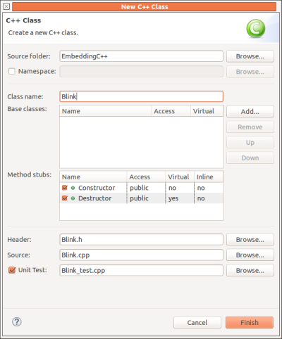
Adding a new class requires creating new header and source files. A wizard does this for you. You enter the class name, a base class name if needed, and select if you want the constructor and destructor created. The files are created with skeleton source code and added to the project.
Wizards also can create new source or header files.
Creating the body of a function or class member is also automated once the function is declared. You first create the declaration in the header file:
int something(const int a);
and then you right click, select ‘Source’ and ‘Implement Method’. A skeleton definition is inserted into the source file:
int something(const int a) {
}
This is especially handy when the function has a long list of parameters.
Often you realize that some lines of code would be better as a new function. This may be so they can be reused in other locations, or just to simplify the flow in the current location. Lifting the code into a new function just requires selecting the code, right clicking, selecting ‘Refactor’, and ‘Extract Function’. A wizard opens for you to approve the new functions parameter list and when you accept this a call to the function replaces the lines and the new function is created.
To illustrate, one set of the duplicated code in loop() can be extracted into a function, outPins, and the duplicate code can be manually replaced with a call to the new function. Not an earth shaking example, admittedly, but it demonstrates the possibilities. The code starts as:
void loop() {
	static unsigned char cnt = 0;
	static bool state = false;

	analogWrite(pin09, cnt);

	// code to extract to make new function
	digitalWrite(pin11, state);
	digitalWrite(pin13, state);
	delay(blink_time);

	state = !state;

	// duplicate code
	digitalWrite(pin11, state);
	digitalWrite(pin13, state);
	delay(blink_time);
}
and after the refactoring becomes:
void loop() {
	static unsigned char cnt = 0;
	static bool state = false;

	analogWrite(pin09, cnt);

	outPins(state);
	state = !state;
	// replace next three lines with outPins(state);
	digitalWrite(pin11, state);
	digitalWrite(pin13, state);
	delay(blink_time);
}
and after a little cut and paste loop() becomes much simpler and maintenance of the lines now in outPins() is easier:
void loop() {
	static unsigned char cnt = 0;
	static bool state = false;

	analogWrite(pin09, cnt);
	outPins(state);
	state = !state;
	outPins(state);
}
Many of these capabilities are refactoring of code, a complex topic that is well worth studying if you will be working on larger projects. The techniques involved improve your code organization without changing the operation.
Caution: Eclipse will make the change you ask for so be sure you have it right. Fixing a massive automatic change can be a nightmare. Been there, done that.
This is just an overview of the advantages of using Eclipse in larger projects. If you are familiar with Eclipse chime in with other capabilities in the comments.
Plug-in Niceties
 All the above is what Eclipse brings. The Arduino plugin also provides a dialog that gives you control over the development parameters by replacing the Arduino IDE drop down menus. You no longer have to go to the menu to first select the board and then go back up to select the port. Also, the dialog allows you to specify compiler options that are buried down in a configuration file with the Arduino IDE. For instance, you can change from the standard optimizing for space to optimizing for speed.
An addition the plug-in brings is an ‘oscilloscope’ graphing window that displays properly formatted data as a curve. This is good for seeing how sensors are reacting to the environment.
Wrap Up
I’ve switched completely to using Eclipse for my Arduino projects. I was already comfortable with Eclipse for other projects so it felt good returning to it for the Arduino. The refactoring and auto-code completion were sorely missed and the other features are icing on the cake.
Filed under: Arduino Hacks, Hackaday Columns, Raspberry Pi, Software Development