Posts | Comments

Planet Arduino

Archive for the ‘isp’ Category

If you’ve been hanging out here at Hackaday for awhile, you’ve certainly seen projects that were based around the concept of putting a miniature computer inside the carcass of some other piece of electronics. In fact at this point it’s something of a running joke, certainly we must have seen an Arduino or Raspberry Pi shoehorned into every type of consumer gadget ever built by this point. But if you thought this would be another example of that common trope by the headline, you might be in for something of a surprise.

[zapta] didn’t put an Arduino inside this GOJO LTX-7 soap dispenser, it was already in there to begin with. That’s right, apparently we’ve hit the point that even cheap soap dispensers are now running on programmable microcontrollers. While we can’t blame those of you who are no doubt groaning and/or rolling their eyes thanks to this particular case of computational gluttony, it does mean we’re able to report with a straight face something which frankly would have passed as an April Fool’s joke in previous years: the development of an open source soap dispensing firmware.

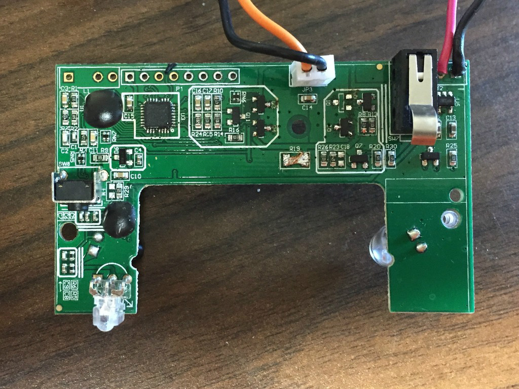
So how does one upload a new Arduino sketch to their GOJO soap dispenser? It’s not like the thing has a USB port on the side for convenient hacking. As explained by [zapta], it involves stripping the dispenser all the way down until the electronics board is free, and then adding in a programming header to make subsequent firmware fiddling a bit easier. Writing a new firmware to the ATTiny48 powered board will require an external ISP (the Atmel AVRISP MKII was used for this hack, though any should work), but it’s otherwise pretty painless.

[zapta] has done an excellent job documenting the different components on the board, and reverse engineered enough of the critical aspects (such as the motor controller and proximity sensor) to write a new open source firmware which can be flashed to the GOJO LTX-7. Beyond allowing you to “Open Source All the Things”, using this new firmware does have some practical advantage in that you can configure how much soap is dispensed per activation. Going further, we’d be exceptionally interested in hearing about anyone who manages to come up with a firmware that enables some hitherto impossible soap dispensing trickery.

We’ve seen hacks involving dispensers of all types, from Halloween games that spit out candy to gadgets which let dogs get their own treats, but a soap dispenser hack is something truly new for us. More proof that there’s still plenty of hardware out there just waiting to be hacked!

Cheap second-hand hardware is usually a fertile ground for hacking, and it looks like these digital classroom aids are no exception. [is0-mick] writes in to tell us how he managed to hack one of these devices, a Smart Reponse XE, into an Arduboy compatible game system. As it turns out, this particular gadget is powered by an ATmega128RFA, which is essentially an Arduino-compatible AVR microcontroller with a 2.4GHz RF transceiver tacked on. This makes it an extremely interesting platform for hacking, especially since they are going for as little as $3 USD on eBay.

There’s no USB-Serial converter built into the Smart Response XE, so you’ll need to provide your own external programmer to flash the device. But luckily there’s a labeled ISP connector right on the board which makes it pretty straightforward to get everything wired up.

Of course, getting the hardware working was slightly more complicated than just flashing an Arduino Sketch onto the thing. [is0-mick] has provided his bootloader and modified libraries to get the device’s QWERTY keyboard and ST7586S controlled 384×160 LCD working.

Playing games is fun, but when his friend [en4rab] sent him the Smart Response XE to fiddle with, the goal was actually to turn them into cheap 2.4 GHz analyzers similar to what was done with the IM-ME. It seems they’re well on their way, and [is0-mick] invites anyone who might be interested in filling in some of the blanks on the RF side to get involved.

An ISP dongle is a very common piece of equipment on a maker’s bench. However, its potential as a hackable device is generally overlooked. The USBASP has an ATmeg8L at its heart and [Robson] decided that this humble USB device could be used as an interface between his PC and a SNES Joypad.

A SNES controller required three pins to communicate with a host: clock, data and latch. In his hack, [Robson]  connects the controller to the ISP interface using a small DIY adaptor and programs the AVR using the V-USB library. V-USB is a software USB library for small microcontrollers and comes in pretty handy in this instance.

[Robson] does a pretty good job of documenting the entire process of creating the interface which includes the USB HID code as well as the SNES joypad serial protocol. His hack works on both Windows and Linux alike and the code is available on GitHub for download.

Simple implementation like this project are a great starting point for anyone looking to dip their toes in the DIY USB device pool. Veterans may find a complete DIY joystick more up their alley and will be inspired by some plastic techniques as well.


Filed under: Arduino Hacks, hardware
Jun
04

LCD clock version 2

arduino, clock, FTDI, isp, LCD, timer Comments Off on LCD clock version 2 

lcdclockv2final_0002-600x399

Here’s an update on Kevin Rye’s LCD clock . Source files are available here, for direct download LCD-Clock-V2-Source.zip:

Once all the components and headers were soldered in, I attached my Arduino and configured it as an ISP. I then burned the bootloader for an Arduino Uno.
I then connected my FTDI programmer and uploaded the blink sketch.Success!

Wow, that LED is super bright! It’s actually blinding and kind of hard to look at. With that, I swapped out the resistor for a 1K one in order to bring the brightness down.
Knowing that the Atmega worked, it was time to solder in the rest of the components, except for the display. Again, I don’t want to come this far and then waste a $15 LCD.

[via]

LCD clock version 2 - [Link]

Apr
01

The Idiot’s Guide to Programming AVR’s on the Cheap

arduino, Atiny85, ATmega328, atmel, ATtiny2313, AVR, isp Comments Off on The Idiot’s Guide to Programming AVR’s on the Cheap 

AVR

Evilthingamabober @ instructables.com writes:

Microcontrollers are, without a doubt, amazing little things. They are versatile, powerful, and extremely tiny. Unfortunately, the latter trait is also shared by both my wallet and my programming skills. My understanding of C is poor, and I can hardly afford to buy something like an Arduino or a decent ISP. And in any case, the Arduino would be overkill for many of my projects, which only need simple IC’s.

But as many of you know, DIY always finds a way. This tutorial is meant for those among us with no budgets or programming experience who want to start using these little machines. It is not based around the ATmega328 (the Arduino Uno chip), but rather the Attiny line of chips (the Atiny85 and Attiny2313, to be specific). The total cost of this project can go as lower than $15 if you know where to buy from, and you can still use the original Arduino IDE and language to program your projects in the end. Keep in mind that you will need some soldering skills to get this project done.

The Idiot’s Guide to Programming AVR’s on the Cheap - [Link]

Jan
30

Building an ISP Shield for Arduino

arduino, isp, shield Comments Off on Building an ISP Shield for Arduino 

FUOL56FHQVLDPCB.MEDIUM

In this article read about how to build an AVR ISP Shield for Arduino. phenoptix writes:

This Instructable is for the build instructions for our new AVR ISP Shield Kit for Arduino. Its development owes a great deal to Instructables and our own community (particularly Nick!) and I hope to explain some of that along the way.

Let me start by saying to program an AVR chip with an Arduino you don’t need a shield or even a crystal if you’re programming Arduino bootloaders. But if you plan on doing it more than once a shield is going to save you some headaches as setting up a breadboard each time and then worrying about debugging is a pain…

Building an ISP Shield for Arduino - [Link]

Jul
26

ATtiny programmer using Arduino ISP

arduino, ATmega328, attiny, ATTiny45, ATTINY85, avrdude, DASA, isp, Mcu, USBtinyISP Comments Off on ATtiny programmer using Arduino ISP 

F2AY9GVGZ0MMEBD.LARGE

JeonLab @ instructables.com writes:

For relatively small (less number of pins than ATmega328) projects, ATtiny series, ATtiny45 or Attiny85 are good choice in terms of its physical size (8-DIP or 8-SOIC) and low power consumption. There are many ways to program it. One of the popular device is USBtinyISP and DASA. Both of them work very well with WinAVR (AVRdude).

ATtiny programmer using Arduino ISP - [Link]

Sep
19

Kit Review – AVR ISP Shield

arduino, AVR, avrisp, DEV-11168, dev11168, isp, kit, kit review, review, shield, sparkfun, tronixstuff Comments Off on Kit Review – AVR ISP Shield 

Introduction

In the last few weeks I needed to flash some ATmega328P microcontrollers with the Arduino bootloader. There are a few ways of doing this, and one method is to use an AVR ISP shield. It’s a simple kit to assemble and use, so let’s  have look at the process and results.

As the kit is manufactured by Sparkfun, it arrives in typical minimalist fashion:

The kit includes the following items:

That’s it – no URL to instructions or getting started guide or anything. Luckily we have a bit of knowledge behind us to understand what’s going on. The PCB has all the components as SMT including the status LEDs, so the only soldering required is the shield header pins and the six or ten-connector for the programming cable. You receive enough header pins to fit everything except for both six and ten – you can have one or the other, but not both. Having some handy I thought adding my own socket would be a good idea, however the pins are placed too closed to the group of six, nixing that idea:

Assembly

After collecting all my regular soldering tools and firing up the ‘888 it was time to get to work:

The first thing to fit were the shield headers. A simple way to do this is to break off the required lengths:

… then fit them to a matching board:

… then you place the shield on top and solder the pins. After that I used some of my own headers to fit both six and ten-pin ISP headers – it never hurts to do both, one day you might need them and not have soldering equipment at the ready. Finally the zero-insertion force (ZIF) socket goes in last. Push the lever down so it lays flat before soldering. Then you’re finished:

Operation

Now to program some raw microcontrollers. Insert the shield into your board. We used Arduino IDE v1.0.1 without modifying the original instructions from the Arduino team. Now upload the “ArduinoISP” sketch which is in the Examples menu. Once this has been successful the PLS LED will breathe. You then insert the microcontroller into the ZIF socket and gently pull the lever down. The notch on the microcontroller must be on the right-hand side when looking at the shield. Finally – check the voltage! There is a switch at the bottom-left of the shield that allows 5V or 3.3V. This only changes the Vcc so programming a 3.3V microcontroller will still involve 5V via SPI – possibly causing trouble.

Next  you need to select the target board for the microcontroller you’re programming. For example, if it’s going into a Uno – click Uno, even if you’re hosting the shield with an older board such as a Duemilanove. Next, choose the programmer type by selecting Tools > Programmer >  Arduino as ISP. Now for the magic – select Tools > Burn bootloader. The process takes around one minute, during which time the “PROG” LED on the shield will blink and flicker. It turns off once finished, and the IDE also notifies you of this. For the curious, the process is in the video below:

As you hopefully noticed earlier a cable is included which allows in-circuit programming from the shield to your existing project or prototype. However we didn’t have use for it at this time, it will come in handy when doing more advanced work later on.

Conclusion

It’s simple and it works. So if you need to flash a whole tube of raw micros with the Arduino bootloader, this is an option. In Australia you can get the kit from Little Bird Electronics. Full-sized images available on flickr. This kit was purchased without notifying the supplier.

In the meanwhile have fun and keep checking into tronixstuff.com. Why not follow things on twitterGoogle+, subscribe  for email updates or RSS using the links on the right-hand column? And join our friendly Google Group – dedicated to the projects and related items on this website. Sign up – it’s free, helpful to each other –  and we can all learn something.


Sep
19

Introduction

In the last few weeks I needed to flash some ATmega328P microcontrollers with the Arduino bootloader. There are a few ways of doing this, and one method is to use an AVR ISP shield. It’s a simple kit to assemble and use, so let’s  have look at the process and results.

As the kit is manufactured by Sparkfun, it arrives in typical minimalist fashion:

The kit includes the following items:

That’s it – no URL to instructions or getting started guide or anything. Luckily we have a bit of knowledge behind us to understand what’s going on. The PCB has all the components as SMT including the status LEDs, so the only soldering required is the shield header pins and the six or ten-connector for the programming cable. You receive enough header pins to fit everything except for both six and ten – you can have one or the other, but not both. Having some handy I thought adding my own socket would be a good idea, however the pins are placed too closed to the group of six, nixing that idea:

Assembly

After collecting all my regular soldering tools and firing up the ‘888 it was time to get to work:

The first thing to fit were the shield headers. A simple way to do this is to break off the required lengths:

… then fit them to a matching board:

… then you place the shield on top and solder the pins. After that I used some of my own headers to fit both six and ten-pin ISP headers – it never hurts to do both, one day you might need them and not have soldering equipment at the ready. Finally the zero-insertion force (ZIF) socket goes in last. Push the lever down so it lays flat before soldering. Then you’re finished:

Operation

Now to program some raw microcontrollers. Insert the shield into your board. We used Arduino IDE v1.0.1 without modifying the original instructions from the Arduino team. Now upload the “ArduinoISP” sketch which is in the Examples menu. Once this has been successful the PLS LED will breathe. You then insert the microcontroller into the ZIF socket and gently pull the lever down. The notch on the microcontroller must be on the right-hand side when looking at the shield. Finally – check the voltage! There is a switch at the bottom-left of the shield that allows 5V or 3.3V. This only changes the Vcc so programming a 3.3V microcontroller will still involve 5V via SPI – possibly causing trouble.

Next  you need to select the target board for the microcontroller you’re programming. For example, if it’s going into a Uno – click Uno, even if you’re hosting the shield with an older board such as a Duemilanove. Next, choose the programmer type by selecting Tools > Programmer >  Arduino as ISP. Now for the magic – select Tools > Burn bootloader. The process takes around one minute, during which time the “PROG” LED on the shield will blink and flicker. It turns off once finished, and the IDE also notifies you of this. For the curious, the process is in the video below:

As you hopefully noticed earlier a cable is included which allows in-circuit programming from the shield to your existing project or prototype. However we didn’t have use for it at this time, it will come in handy when doing more advanced work later on.

Conclusion

It’s simple and it works. So if you need to flash a whole tube of raw micros with the Arduino bootloader, this is an option. Full-sized images available on flickr. This kit was purchased without notifying the supplier.

In the meanwhile have fun and keep checking into tronixstuff.com. Why not follow things on twitterGoogle+, subscribe  for email updates or RSS using the links on the right-hand column? And join our friendly Google Group – dedicated to the projects and related items on this website. Sign up – it’s free, helpful to each other –  and we can all learn something.

The post Kit Review – AVR ISP Shield appeared first on tronixstuff.


  • Newsletter

    Sign up for the PlanetArduino Newsletter, which delivers the most popular articles via e-mail to your inbox every week. Just fill in the information below and submit.

  • Like Us on Facebook