Over the last few years you may have noticed a few of my Arduino tutorials, and during this time many people have mentioned that I should write a book. And now thanks to the team from No Starch Press this recommendation has morphed into my first book – “Arduino Workshop“:
Now into the fourth print run, “Arduino Workshop” is one of the few books on the market that can take the reader from zero knowledge to understanding the Arduino development platform, and working with a huge array of add-ons and technologies. You don’t need to buy any other preliminary book – this starts from the absolute beginning. And a huge “thank you” to all those who have purchased and supported the book so far – and it’s now available in Traditional Chinese, Korean, German and Polish.
“Arduino Workshop” offers a professionally edited and curated path for the beginner to learn with and have fun. It’s a hands-on introduction to Arduino with 65 projects – from simple LED use right through to RFID, Internet connection, wireless data, working with cellular communications, and much more. Plus the reader also learns about electronics, good coding and other interesting topics.
Each project is explained in detail, explaining how the hardware and Arduino code works together. Plus we teach you how to read and understand circuit schematics and use this clear method of describing circuits which prepares the read for further electronics learning.
The reader doesn’t need any expensive tools or workspaces, and all the parts used are available from almost any electronics retailer. Furthermore all of the projects can be finished without soldering, so it’s safe for readers of all ages.
The editing team at No Starch Press, our technical editor Marc Alexander and myself have worked hard to make the book perfect for those without any electronics or Arduino experience at all, and it makes a great gift for someone to get them started. After working through the 65 projects the reader will have gained enough knowledge and confidence to create many things – and to continue researching on their own.
Or if you’ve been enjoying the results of my thousands of hours of work here at tronixstuff, you can show your appreciation by ordering a copy for yourself or as a gift. If you’re still not sure, review the table of contents, index and download a sample chapter from the Arduino Workshop website.
Arduino Workshop is available from No Starch Press in printed or DRM-free eBook (PDF, Mobi, and ePub) formats. And the eBooks are also included with the printed orders from No Starch Press so you can get started immediately.
Furthermore for readers outside of the United States wishing to save on postage, Arduino Workshop is available from many stores in various countries, for example:
Like your store listed? Send link via Contact Page
And you can also find Arduino Workshop for sale from all the popular booksellers around the globe such as Amazon, Barnes and Noble, and so on.
Have fun and keep checking into tronixstuff.com. Why not follow things on twitter, Google+, subscribe for email updates or RSS using the links on the right-hand column, or join our forum – dedicated to the projects and related items on this website. Sign up – it’s free, helpful to each other – and we can all learn something.
Numeric keypads can provide a simple end-user alternative for various interfaces for your projects. Or if you need a lot of buttons, they can save you a lot of time with regards to construction. We’ll run through connecting them, using the Arduino library and then finish with a useful example sketch.
Getting Started
Numeric keypads are available from many retailers, and no matter where you get them from, make sure you can get the data sheet, as this will make life easier when wiring them up. Here are the two examples for our tutorial, from Futurlec (slow and cheap):
Again, the data sheet is important as it will tell you which pins or connectors on the keypad are for the rows and columns, for example the black keypad shown above. If you don’t have the data sheet – you will need to manually determine which contacts are for the rows and columns.
This can be done using the continuity function of a multimeter (the buzzer). Start by placing one probe on pin 1, the other probe on pin 2, and press the keys one by one. Make a note of when a button completes the circuit, then move onto the next pin. Soon you will know which is which. For example, on the example keypad pins 1 and 5 are for button “1″, 2 and 5 for “4″, etc…
Furthermore some keypads will have the pins soldered to the end, some will not. With our two example keypads, the smaller unit had the pins – and we soldered pins to the large white unit:
At this point please download and install the keypad Arduino library. Now we’ll demonstrate how to use both keypads in simple examples.
Wire up your LCD then connect the keypad to the Arduino in the following manner:
Keypad row 1 to Arduino digital 5
Keypad row 2 to Arduino digital 4
Keypad row 3 to Arduino digital 3
Keypad row 4 to Arduino digital 2
Keypad column 1 to Arduino digital 8
Keypad column 2 to Arduino digital 7
Keypad column 3 to Arduino digital 6
If your keypad is different to ours, take note of the lines in the sketch from:
// keypad type definition
As you need to change the numbers in the arrays rowPins[ROWS] and colPins[COLS]. You enter the digital pin numbers connected to the rows and columns of the keypad respectively.
Furthermore, the array keys stores the values displayed in the LCD when a particular button is pressed. You can see we’ve matched it with the physical keypad used, however you can change it to whatever you need. But for now, enter and upload the following sketch once you’re satisfied with the row/pin number allocations:
/* Numeric keypad and I2C LCD
   https://tronixstuff.com/tutorials > chapter 42
   Uses Keypad library for Arduino
   http://www.arduino.cc/playground/Code/Keypad
   by Mark Stanley, Alexander Brevig */

#include "Keypad.h"
#include "Wire.h" // for I2C LCD
#include "LiquidCrystal_I2C.h" // for I2C bus LCD module
// http://www.dfrobot.com/wiki/index.php/I2C/TWI_LCD1602_Module_(SKU:_DFR0063)
LiquidCrystal_I2C lcd(0x27,16,2);  // set the LCD address to 0x27 for a 16 chars and 2 line display

// keypad type definition
const byte ROWS = 4; //four rows
const byte COLS = 3; //three columns
char keys[ROWS][COLS] =
 {{'1','2','3'},
  {'4','5','6'},
  {'7','8','9'},
  {'*','0','#'}};

byte rowPins[ROWS] = {
  5, 4, 3, 2}; //connect to the row pinouts of the keypad
byte colPins[COLS] = {
  8, 7, 6}; // connect to the column pinouts of the keypad

int count=0;

Keypad keypad = Keypad( makeKeymap(keys), rowPins, colPins, ROWS, COLS );

void setup()
{
  lcd.init();          // initialize the lcd
  lcd.backlight(); // turn on LCD backlight
}

void loop()
{
  char key = keypad.getKey();
  if (key != NO_KEY)
  {
    lcd.print(key);
    count++;
    if (count==17)
    {
      lcd.clear();
      count=0;
    }
  }
}
So now you can see how the button presses can be translated into data for use in a sketch. We’ll now repeat this demonstration with the larger keypad.
Using a 16 digit keypad
We’ll use the larger white 4×4 keypad from Futurlec, an Arduino Uno-compatible and for a change the I2C LCD from Akafugu for display purposes. (We reviewed these previously). Again, if you don’t have an LCD you could always send the text to the serial monitor instead. Wire up the LCD and then connect the keypad to the Arduino in the following manner:
Keypad row 1 (pin eight) to Arduino digital 5
Keypad row 2 (pin 1) to Arduino digital 4
Keypad row 3 (pin 2) to Arduino digital 3
Keypad row 4 (pin 4) to Arduino digital 2
Keypad column 1 (pin 3) to Arduino digital 9
Keypad column 2 (pin 5) to Arduino digital 8
Keypad column 3 (pin 6) to Arduino digital 7
Keypad column 4 (pin 7) to Arduino digital 6
Now for the sketch – take note how we have accommodated for the larger numeric keypad:
the extra column in the array char keys[]
the extra pin in the array colPins[]
and the byte COLS = 4.
/* Numeric keypad and I2C LCD
   https://tronixstuff.com/tutorials > chapter 42
   Uses Keypad library for Arduino
   http://www.arduino.cc/playground/Code/Keypad
   by Mark Stanley, Alexander Brevig */

#include "Keypad.h"
#include "Wire.h" // for I2C LCD
#include "TWILiquidCrystal.h"
// http://store.akafugu.jp/products/26
LiquidCrystal lcd(12, 11, 5, 4, 3, 2);

const byte ROWS = 4; //four rows
const byte COLS = 4; //four columns
char keys[ROWS][COLS] =
 {{'1','2','3','A'},
  {'4','5','6','B'},
  {'7','8','9','C'},
  {'*','0','#','D'}};
byte rowPins[ROWS] = {
  5, 4, 3, 2}; //connect to the row pinouts of the keypad
byte colPins[COLS] = {
  9, 8, 7, 6}; //connect to the column pinouts of the keypad
int count=0;

Keypad keypad = Keypad( makeKeymap(keys), rowPins, colPins, ROWS, COLS );

void setup()
{
  Serial.begin(9600);
  lcd.begin(16, 2);
  lcd.print("Keypad test!");
  delay(1000);
  lcd.clear();
}

void loop()
{
  char key = keypad.getKey();
  if (key != NO_KEY)
  {
    lcd.print(key);
    Serial.print(key);
    count++;
    if (count==17)
    {
      lcd.clear();
      count=0;
    }
  }
}
And again you can see the results of the sketch above in this video.
And now for an example project, one which is probably the most requested use of the numeric keypad…
Example Project – PIN access system
The most-requested use for a numeric keypad seems to be a “PIN” style application, where the Arduino is instructed to do something based on a correct number being entered into the keypad. The following sketch uses the hardware described for the previous sketch and implements a six-digit PIN entry system. The actions to take place can be inserted in the functions correctPIN() and incorrectPIN(). And the PIN is set in the array char PIN[6]. With a little extra work you could create your own PIN-change function as well.
// PIN switch with 16-digit numeric keypad
// https://tronixstuff.com/tutorials > chapter 42

#include "Keypad.h"
#include <Wire.h>
#include <TWILiquidCrystal.h>
LiquidCrystal lcd(12, 11, 5, 4, 3, 2);

const byte ROWS = 4; //four rows
const byte COLS = 4; //four columns
char keys[ROWS][COLS] =
{
  {
    '1','2','3','A'  }
  ,
  {
    '4','5','6','B'  }
  ,
  {
    '7','8','9','C'  }
  ,
  {
    '*','0','#','D'  }
};
byte rowPins[ROWS] = {
  5, 4, 3, 2}; //connect to the row pinouts of the keypad
byte colPins[COLS] = {
  9, 8, 7, 6}; //connect to the column pinouts of the keypad

Keypad keypad = Keypad( makeKeymap(keys), rowPins, colPins, ROWS, COLS );

char PIN[6]={
  '1','2','A','D','5','6'}; // our secret (!) number
char attempt[6]={
  '0','0','0','0','0','0'}; // used for comparison
int z=0;

void setup()
{
  Serial.begin(9600);
  lcd.begin(16, 2);
  lcd.print("PIN Lock ");
  delay(1000);
  lcd.clear();
  lcd.print("  Enter PIN...");
}

void correctPIN() // do this if correct PIN entered
{
  lcd.print("* Correct PIN *");
  delay(1000);
  lcd.clear();
  lcd.print("  Enter PIN...");
}

void incorrectPIN() // do this if incorrect PIN entered
{
  lcd.print(" * Try again *");
  delay(1000);
  lcd.clear();
  lcd.print("  Enter PIN...");
}

void checkPIN()
{
  int correct=0;
  int i;
  for ( i = 0;   i < 6 ;  i++ )
  {

    if (attempt[i]==PIN[i])
    {
      correct++;
    }
  }
  if (correct==6)
  {
    correctPIN();
  }
  else
  {
    incorrectPIN();
  }

  for (int zz=0; zz<6; zz++)
  {
    attempt[zz]='0';
  }
}

void readKeypad()
{
  char key = keypad.getKey();
  if (key != NO_KEY)
  {
    attempt[z]=key;
    z++;
    switch(key)
    {
    case '*':
      z=0;
      break;
    case '#':
      z=0;
      delay(100); // for extra debounce
      lcd.clear();
      checkPIN();
      break;
    }
  }
}

void loop()
{
  readKeypad();
}
So now you have the ability to use twelve and sixteen-button keypads with your Arduino systems. I’m sure you will come up with something useful and interesting using the keypads in the near future.
Stay tuned for upcoming Arduino tutorials by subscribing to the blog, RSS feed (top-right), twitter or joining our Google Group. And if you enjoyed the tutorial, or want to introduce someone else to the interesting world of Arduino – check out my book (now in a third printing!) “Arduino Workshop” from No Starch Press.
In this chapter we’ll look at how you can measure smaller voltages with greater accuracy using the analogue input pins on your Arduino or compatible board in conjunction with the AREF pin. However first we’ll do some revision to get you up to speed. Please read this post entirely before working with AREF the first time.
Revision
You may recall from the first few chapters in our tutorial series that we used the analogRead() function to measure the voltage of an electrical current from sensors and so on using one of the analogue input pins. The value returned from analogRead() would be between zero an 1023, with zero representing zero volts and 1023 representing the operating voltage of the Arduino board in use.
And when we say the operating voltage – this is the voltage available to the Arduino afterthe power supply circuitry. For example, if you have a typical Arduino Uno board and run it from the USB socket – sure, there is 5V available to the board from the USB socket on your computer or hub – but the voltage is reduced slightly as the current winds around the circuit to the microcontroller – or the USB source just isn’t up to scratch.
This can easily be demonstrated by connecting an Arduino Uno to USB and putting a multimeter set to measure voltage across the 5V and GND pins. Some boards will return as low as 4.8 V, some higher but still below 5V. So if you’re gunning for accuracy, power your board from an external power supply via the DC socket or Vin pin – such as 9V DC. Then after that goes through the power regulator circuit you’ll have a nice 5V, for example:
This is important as the accuracy of any analogRead() values will be affected by not having a true 5 V. If you don’t have any option, you can use some maths in your sketch to compensate for the drop in voltage. For example, if your voltage is 4.8V – the analogRead() range of 0~1023 will relate to 0~4.8V and not 0~5V. This may sound trivial, however if you’re using a sensor that returns a value as a voltage (e.g. the TMP36 temperature sensor) – the calculated value will be wrong. So in the interests of accuracy, use an external power supply.
Why does analogRead() return a value between 0 and 1023?
This is due to the resolution of the ADC. The resolution (for this article) is the degree to which something can be represented numerically. The higher the resolution, the greater accuracy with which something can be represented. We measure resolution in the terms of the number of bits of resolution.
For example, a 1-bit resolution would only allow two (two to the power of one) values – zero and one. A 2-bit resolution would allow four (two to the power of two) values – zero, one, two and three. If we tried to measure a five volt range with a two-bit resolution, and the measured voltage was four volts, our ADC would return a numerical value of 3 – as four volts falls between 3.75 and 5V. It is easier to imagine this with the following image:
So with our example ADC with 2-bit resolution, it can only represent the voltage with four possible resulting values. If the input voltage falls between 0 and 1.25, the ADC returns numerical 0; if the voltage falls between 1.25 and 2.5, the ADC returns a numerical value of 1. And so on. With our Arduino’s ADC range of 0~1023 – we have 1024 possible values – or 2 to the power of 10. So our Arduinos have an ADC with a 10-bit resolution.
So what is AREF?
To cut a long story short, when your Arduino takes an analogue reading, it compares the voltage measured at the analogue pin being used against what is known as the reference voltage. In normal analogRead use, the reference voltage is the operating voltage of the board. For the more popular Arduino boards such as the Uno, Mega, Duemilanove and Leonardo/Yún boards, the operating voltage of 5V. If you have an Arduino Due board, the operating voltage is 3.3V. If you have something else – check the Arduino product page or ask your board supplier.
So if you have a reference voltage of 5V, each unit returned by analogRead() is valued at 0.00488 V. (This is calculated by dividing 1024 into 5V). What if we want to measure voltages between 0 and 2, or 0 and 4.6? How would the ADC know what is 100% of our voltage range?
And therein lies the reason for the AREF pin. AREF means Analogue REFerence. It allows us to feed the Arduino a reference voltage from an external power supply. For example, if we want to measure voltages with a maximum range of 3.3V, we would feed a nice smooth 3.3V into the AREF pin – perhaps from a voltage regulator IC. Then the each step of the ADC would represent around 3.22 millivolts (divide 1024 into 3.3).
Note that the lowest reference voltage you can have is 1.1V. There are two forms of AREF – internal and external, so let’s check them out.
External AREF
An external AREF is where you supply an external reference voltage to the Arduino board. This can come from a regulated power supply, or if you need 3.3V you can get it from the Arduino’s 3.3V pin. If you are using an external power supply, be sure to connect the GND to the Arduino’s GND pin. Or if you’re using the Arduno’s 3.3V source – just run a jumper from the 3.3V pin to the AREF pin.
To activate the external AREF, use the following in void setup():
analogReference(EXTERNAL); // use AREF for reference voltage
This sets the reference voltage to whatever you have connected to the AREF pin – which of course will have a voltage between 1.1V and the board’s operation voltage.
Very important note – when using an external voltage reference, you must set the analogue reference to EXTERNAL before using analogRead(). This will prevent you from shorting the active internal reference voltage and the AREF pin, which can damage the microcontroller on the board.
If necessary for your application, you can revert back to the board’s operating voltage for AREF (that is – back to normal) with the following:
analogReference(DEFAULT);
Now to demonstrate external AREF at work. Using a 3.3V AREF, the following sketch measures the voltage from A0 and displays the percentage of total AREF and the calculated voltage:
#include <LiquidCrystal.h>
LiquidCrystal lcd(8,9,4,5,6,7);

int analoginput = 0; // our analog pin
int analogamount = 0; // stores incoming value
float percentage = 0; // used to store our percentage value
float voltage =0; // used to store voltage value

void setup()
{
  lcd.begin(16, 2);
  analogReference(EXTERNAL); // use AREF for reference voltage
}

void loop()
{
  lcd.clear();
  analogamount=analogRead(analoginput);
  percentage=(analogamount/1024.00)*100;
  voltage=analogamount*3.222; // in millivolts
  lcd.setCursor(0,0);
  lcd.print("% of AREF: ");
  lcd.print(percentage,2);
  lcd.setCursor(0,1);
  lcd.print("A0 (mV): ");
  lcd.println(voltage,2);
  delay(250);
}
The results of the sketch above are shown in the following video:
Internal AREF
The microcontrollers on our Arduino boards can also generate an internal reference voltage of 1.1V and we can use this for AREF work. Simply use the line:
analogReference(INTERNAL);
For Arduino Mega boards, use:
analogReference(INTERNAL1V1);
in void setup() and you’re off. If you have an Arduino Mega there is also a 2.56V reference voltage available which is activated with:
analogReference(INTERNAL2V56);
Finally – before settling on the results from your AREF pin, always calibrate the readings against a known good multimeter.
Conclusion
The AREF function gives you more flexibility with measuring analogue signals. If you are interested in using specific ADC components, we have tutorials on the ADS1110 16-bit ADC and the NXP PCF 8591 8-bit A/D and D/A IC.
Stay tuned for upcoming Arduino tutorials by subscribing to the blog, RSS feed (top-right), twitter or joining our Google Group. And if you enjoyed the tutorial, or want to introduce someone else to the interesting world of Arduino – check out my book (now in a third printing!) “Arduino Workshop” from No Starch Press.
In this chapter we will introduce and examine the use of Ethernet networking with Arduino over local networks and the greater Internet. It will be assumed that you have a basic understanding of computer networking, such as the knowledge of how to connect computers to a hub/router with RJ45 cables, what an IP and MAC address is, and so on. Furthermore, here is a good quick rundown about Ethernet.
Getting Started
You will need an Arduino Uno or compatible board with an Ethernet shield that uses the W5100 Ethernet controller IC (pretty much all of them):
…or consider using a Freetronics EtherTen – as it has everything all on the one board, plus some extras:
Furthermore you will need to power the board via the external DC socket – the W5100 IC uses more current than the USB power can supply. A 9V 1A plug pack/wall wart will suffice. Finally it does get hot – so be careful not to touch the W5100 after extended use. In case you’re not sure – this is the W5100 IC:
Once you have your Ethernet-enabled Arduino, and have the external power connected – it’s a good idea to check it all works. Open the Arduino IDE and selectFile > Examples > Ethernet > Webserver. This loads a simple sketch which will display data gathered from the analogue inputs on a web browser. However don’t upload it yet, it needs a slight modification.
You need to specify the IP address of the Ethernet shield – which is done inside the sketch. This is simple, go to the line:
IPAddress ip(192,168,1, 177);
And alter it to match your own setup. For example, in my home the router’s IP address is 10.1.1.1, the printer is 10.1.1.50 and all PCs are below …50. So I will set my shield IP to 10.1.1.77 by altering the line to:
IPAddress ip(10,1,1,77);
You also have the opportunity to change your MAC address. Each piece of networking equipment has a unique serial number to identify itself over a network, and this is normall hard-programmed into the equipments’ firmware. However with Arduino we can define the MAC address ourselves.
If you are running more than one Ethernet shield on your network, ensure they have different MAC addresses by altering the hexadecimal values in the line:
However if you only have one shield just leave it be. There may be the very, very, statistically rare chance of having a MAC address the same as your existing hardware, so that would be another time to change it.
Once you have made your alterations, save and upload the sketch. Now open a web browser and navigate to the IP address you entered in the sketch, and you should be presented with something similar to the following:
What’s happening? The Arduino has been programmed to offer a simple web page with the values measured by the analogue inputs. You can refresh the browser to get updated values.
At this point – please note that the Ethernet shields use digital pins 10~13, so you can’t use those for anything else. Some Arduino Ethernet shields may also have a microSD card socket, which also uses another digital pin – so check with the documentation to find out which one.
Nevertheless, now that we can see the Ethernet shield is working we can move on to something more useful. Let’s dissect the previous example in a simple way, and see how we can distribute and display more interesting data over the network. For reference, all of the Ethernet-related functions are handled by the Ethernet Arduino library. If you examine the previous sketch we just used, the section that will be of interest is:
 for (int analogChannel = 0; analogChannel < 6; analogChannel++)
          {
            int sensorReading = analogRead(analogChannel);
            client.print("analog input ");
            client.print(analogChannel);
            client.print(" is ");
            client.print(sensorReading);
            client.println("<br />");
          }
          client.println("</html>");
Hopefully this section of the sketch should be familiar – remember how we have used serial.print(); in the past when sending data to the serial monitor box? Well now we can do the same thing, but sending data from our Ethernet shield back to a web browser – on other words, a very basic type of web page.
However there is something you may or may not want to learn in order to format the output in a readable format – HTML code. I am not a website developer (!) so will not delve into HTML too much.
However if you wish to serve up nicely formatted web pages with your Arduino and so on, here would be a good start. In the interests of simplicity, the following two functions will be the most useful:
client.print(" is ");
Client.print (); allows us to send text or data back to the web page. It works in the same way as serial.print(), so nothing new there. You can also specify the data type in the same way as with serial.print(). Naturally you can also use it to send data back as well. The other useful line is:
client.println("<br />");
which sends the HTML code back to the web browser telling it to start a new line. The part that actually causes the carriage return/new line is the <br /> which is an HTML code (or “tag”) for a new line. So if you are creating more elaborate web page displays, you can just insert other HTML tags in the client.print(); statement. If you want to learn more about HTML commands, here’s a good tutorial site. Finally – note that the sketch will only send the data when it has been requested, that is when it has received a request from the web browser.
Accessing your Arduino over the Internet
So far – so good. But what if you want to access your Arduino from outside the local network?
You will need a static IP address – that is, the IP address your internet service provider assigns to your connection needs to stay the same. If you don’t have a static IP, as long as you leave your modem/router permanently swiched on your IP shouldn’t change. However that isn’t an optimal solution.
If your ISP cannot offer you a static IP at all, you can still move forward with the project by using an organisation that offers a Dynamic DNS. These organisations offer you your own static IP host name (e.g. mojo.monkeynuts.com) instead of a number, keep track of your changing IP address and linking it to the new host name. From what I can gather, your modem needs to support (have an in-built client for…) these DDNS services. As an example, two companies are No-IP andDynDNS.com. Please note that I haven’t used those two, they are just offered as examples.
Now, to find your IP address… usually this can be found by logging into your router’s administration page – it is usually 192.168.0.1 but could be different. Check with your supplier or ISP if they supplied the hardware. For this example, if I enter 10.1.1.1 in a web browser, and after entering my modem administration password, the following screen is presented:
What you are looking for is your WAN IP address, as you can see in the image above. To keep the pranksters away, I have blacked out some of my address.
The next thing to do is turn on port-forwarding. This tells the router where to redirect incoming requests from the outside world. When the modem receives such a request, we want to send that request to the port number of our Ethernet shield. Using the:
EthernetServer server(125);
function in our sketch has set the port number to 125. Each modem’s configuration screen will look different, but as an example here is one:
So you can see from the line number one in the image above, the inbound port numbers have been set to 125, and the IP address of the Ethernet shield has been set to 10.1.1.77 – the same as in the sketch.
After saving the settings, we’re all set. The external address of my Ethernet shield will be the WAN:125, so to access the Arduino I will type my WAN address with :125 at the end into the browser of the remote web device, which will contact the lonely Ethernet hardware back home.
Furthermore, you may need to alter your modem’s firewall settings, to allow the port 125 to be “open” to incoming requests. Please check your modem documentation for more information on how to do this.
Now from basically any Internet connected device in the free world, I can enter my WAN and port number into the URL field and receive the results. For example, from a phone when it is connected to the Internet via LTE mobile data:
So at this stage you can now display data on a simple web page created by your Arduino and access it from anywhere with unrestricted Internet access. With your previous Arduino knowledge (well, this is chapter sixteen) you can now use data from sensors or other parts of a sketch and display it for retrieval.
Displaying sensor data on a web page
As an example of displaying sensor data on a web page, let’s use an inexpensive and popular temperature and humidity sensor – the DHT22. You will need to install the DHT22 Arduino library which can be found on this page. If this is your first time with the DHT22, experiment with the example sketch that’s included with the library so you understand how it works.
Connect the DHT22 with the data pin to Arduino D2, Vin to the 5V pin and GND to … GND:
Now for our sketch – to display the temperature and humidity on a web page. If you’re not up on HTML you can use online services such as this to generate the code, which you can then modify to use in the sketch.
In the example below, the temperature and humidity data from the DHT22 is served in a simple web page:
#include <SPI.h>
#include <Ethernet.h>

// for DHT22 sensor
#include "DHT.h"
#define DHTPIN 2
#define DHTTYPE DHT22

// Enter a MAC address and IP address for your controller below.
// The IP address will be dependent on your local network:
byte mac[] = {   0xDE, 0xAD, 0xBE, 0xEF, 0xFE, 0xED };
IPAddress ip(10,1,1,77);

// Initialize the Ethernet server library
// with the IP address and port you want to use
// (port 80 is default for HTTP):
EthernetServer server(125);
DHT dht(DHTPIN, DHTTYPE);

void setup()
{
  dht.begin();
 // Open serial communications and wait for port to open:
  Serial.begin(9600);
   while (!Serial) {
    ; // wait for serial port to connect. Needed for Leonardo only
  }
  // start the Ethernet connection and the server:
  Ethernet.begin(mac, ip);
  server.begin();
  Serial.print("server is at ");
  Serial.println(Ethernet.localIP());
}

void loop()
{
  // listen for incoming clients
  EthernetClient client = server.available();
  if (client) {
    Serial.println("new client");
    // an http request ends with a blank line
    boolean currentLineIsBlank = true;
    while (client.connected()) {
      if (client.available()) {
        char c = client.read();
        Serial.write(c);
        // if you've gotten to the end of the line (received a newline
        // character) and the line is blank, the http request has ended,
        // so you can send a reply
        if (c == 'n' && currentLineIsBlank)
        {
          // send a standard http response header
          client.println("HTTP/1.1 200 OK");
          client.println("Content-Type: text/html");
          client.println("Connection: close");  // the connection will be closed after completion of the response
	  client.println("Refresh: 30");  // refresh the page automatically every 30 sec
          client.println();
          client.println("<!DOCTYPE HTML>");
          client.println("<html>");

          // get data from DHT22 sensor
          float h = dht.readHumidity();
          float t = dht.readTemperature();
          Serial.println(t);
          Serial.println(h);

          // from here we can enter our own HTML code to create the web page
          client.print("<head><title>Office Weather</title></head><body><h1>Office Temperature</h1><p>Temperature - ");
          client.print(t);
          client.print(" degrees Celsius</p>");
          client.print("<p>Humidity - ");
          client.print(h);
          client.print(" percent</p>");
          client.print("<p><em>Page refreshes every 30 seconds.</em></p></body></html>");
          break;
        }
        if (c == 'n') {
          // you're starting a new line
          currentLineIsBlank = true;
        }
        else if (c != 'r') {
          // you've gotten a character on the current line
          currentLineIsBlank = false;
        }
      }
    }
    // give the web browser time to receive the data
    delay(1);
    // close the connection:
    client.stop();
    Serial.println("client disonnected");
  }
}
It is a modification of the IDE’s webserver example sketch that we used previously – with a few modifications. First, the webpage will automatically refresh every 30 seconds – this parameter is set in the line:
client.println("Refresh: 30"); // refresh the page automatically every 30 sec
… and the custom HTML for our web page starts below the line:
// from here we can enter our own HTML code to create the web page
You can then simply insert the required HTML inside client.print() functions to create the layout you need.
Finally – here’s an example screen shot of the example sketch at work:
You now have the framework to create your own web pages that can display various data processed with your Arduino.
Remote control your Arduino from afar
We have a separate tutorial on this topic, that uses the teleduino system.
Conclusion
So there you have it, another useful way to have your Arduino interact with the outside world. Stay tuned for upcoming Arduino tutorials by subscribing to the blog, RSS feed (top-right), twitter or joining our Google Group. And if you enjoyed the tutorial, or want to introduce someone else to the interesting world of Arduino – check out my book (now in a third printing!) “Arduino Workshop” from No Starch Press.
In this article you will learn how to send messages from an Ethernet-enabled Arduino to twitter. For the uninitiated who may be thinking “what is all this twitter nonsense about?”, twitter is a form of microblogging.
You can create a message with a maximum length of 140 characters, and broadcast this on the twitter service. For people to receive your messages (or tweets) they also need to be a member of twitter and choose to subscribe to your tweets.
Generally people will use the twitter service using one of two methods: either using a web browser, or using the twitter application on a smartphone or tablet computer. For example, here is a typical web browser view:
… and here is an example of a twitter application running on an Android OS smartphone:
The neat thing about twitter on a mobile device is that if your username is mentioned in a tweet, you will be notified pretty well immediately as long as you have mobile data access. More on that later. In some areas, you can set twitter to send tweets from a certain user to your mobile phone via SMS – however if doing so be careful to confirm possible charges to your mobile phone account.
Finally, if you are worried about privacy with regards to your tweets, you can set your account to private and only allow certain people to follow your tweets.
So let’s get started.
First of all – you will need a twitter account. If you do not have one, you can sign up for one here. If you already have a twitter account, you can always open more for other uses – such as an Arduino.
For example, my twitter account is @tronixstuff, but my demonstration machine twitter account is @tronixstuff2. Then I have set my primary account to follow my machine’s twitter account.
Now log into twitter with using the account you will have for your Arduino and visit this page and get yourself a token by following the Step One link. The process will take you through authorising the “tweet library” page to login to your twitter account – this is ok. It will then present you with a long text called a “token”, for example:
Save your token somewhere safe, as you will need to insert it into your Arduino sketch. Finally, don’t give it to others as then they will be able to post onto twitter using your account. Next, follow step two from the same page – which involves download and installation of the required Arduino library.
Now for the hardware.
You will need an Arduino Uno or compatible board with an Ethernet shield that uses the W5100 Ethernet controller IC (pretty much all of them) – or consider using a Freetronics EtherTen – as it has everything all on the one board, plus some extras:
Furthermore you will need to power the board via the external DC socket – the W5100 IC uses more current than the USB power can supply. A 9V 1A plug pack/wall wart will suffice. Finally it does get hot – so be careful not to touch the W5100 after extended use. In case you’re not sure – this is the W5100 IC:
If you’re looking for an Arduino-twitter solution with WiFi, check out the Arduino Yún tutorials.
From this point it would be a good idea to check your hardware is working. To do so, please run the webserver example sketch as explained in chapter sixteen (Ethernet). While you do that, we’ll have a break…
Sending your first tweet
If you want your Arduino to send a simple tweet consider the following sketch. We have a simple function tweet() which simply sends a line of text (which has a maximum length of 140 characters). Don’t forget to update your IP address, MAC address and token:
// Simple twitter interface

#include <SPI.h>
#include <Ethernet.h>
#include <Twitter.h>

// Alter IP address to suit your own network!
byte mac[] = {   0xDE, 0xAD, 0xBE, 0xEF, 0xFE, 0xED }; // create MAC address for ethernet shield
byte ip[] = {   192, 168, 0, 99}; // choose your own IP for ethernet shield
Twitter twitter("aaaaaaa"); // replace aaaaaaa with your token

void setup()
{
  delay(5000);
  Ethernet.begin(mac, ip);
  Serial.begin(9600);
}

void tweet(char msg[])
{
  Serial.println("connecting ...");
  if (twitter.post(msg))
  {
    // Specify &Serial to output received response to Serial.
    // If no output is required, you can just omit the argument, e.g.
    // int status = twitter.wait();
    int status = twitter.wait(&Serial);
    if (status == 200)
    {
      Serial.println("OK.");
    }
    else
    {
      Serial.print("failed : code ");
      Serial.println(status);
    }
  }
  else
  {
    Serial.println("connection failed.");
  }
}

void loop()
{
  delay(1000);
  tweet("Purple monkey dishwasher");
  do{} while(1>0); // endless loop
}
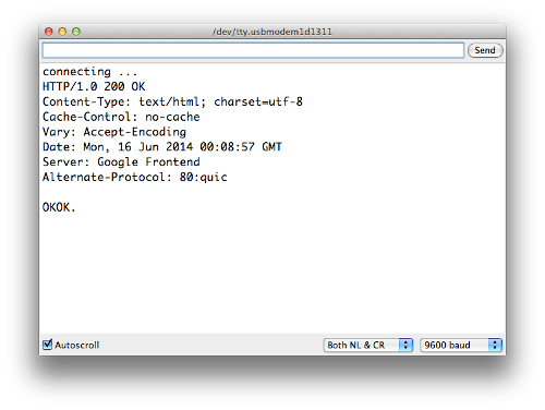
You can check the status of the tweeting via the serial monitor. For example, if the tweet was successful you will see:
However if you try to send the same tweet more than once in a short period of time, or another error takes place – twitter will return an error message, for example:
And finally if it works, the tweet will appear:
Previously we mentioned that you can be alerted to a tweet by your mobile device. This can be done by putting your own twitter account name in the contents of the tweet.
For example – my normal twitter account is @tronixstuff. If I put the text “@tronixstuff” in the text tweeted by my Arduino’s twitter account – the twitter app on my smartphone will let me know I have been mentioned – as shown in the following video:
You may have noticed in the video that a text message arrived as well – that service is a function of my cellular carrier (Telstra) and may not be available to others. Nevertheless this is a neat way of getting important messages from your Arduino to a smart phone or other connected device.
Sending data in a tweet
So what if you have a sensor or other device whose data you want to know about via twitter? You can send data generated from an Arduino sketch over twitter without too much effort.
In the following example we’ll send the value from analogue pin zero (A0) in the contents of a tweet. And by adding your twitter @username you will be notified by your other twitter-capable devices:
// Simple twitter interface

#include <SPI.h>
#include <Ethernet.h>
#include <Twitter.h>

// Alter IP address to suit your own network!
byte mac[] = {   0xDE, 0xAD, 0xBE, 0xEF, 0xFE, 0xED }; // create MAC address for ethernet shield
byte ip[] = {   192, 168, 0, 99}; // choose your own IP for ethernet shield
Twitter twitter("aaaaaaa"); // replace aaaaaaa with your token

int analogZero;
char tweetText[140];

void setup()
{
  delay(5000);
  Ethernet.begin(mac, ip);
  Serial.begin(9600);
}

void tweet(char msg[])
{
  Serial.println("connecting ...");
  if (twitter.post(msg))
  {
    // Specify &Serial to output received response to Serial.
    // If no output is required, you can just omit the argument, e.g.
    // int status = twitter.wait();
    int status = twitter.wait(&Serial);
    if (status == 200)
    {
      Serial.println("OK.");
    }
    else
    {
      Serial.print("failed : code ");
      Serial.println(status);
    }
  }
  else
  {
    Serial.println("connection failed.");
  }
}

void loop()
{
  // get some data from A0.
  analogZero=analogRead(0);

  // assemble message to send. This inserts the value of "analogZero" into the variable "tweetText" at point %d
  sprintf(tweetText, "Pin analogue zero reads: %d. @username.", analogZero); // change @username to your twitter account name

  delay(1000);
  tweet(tweetText);
  do{ }
  while(1>0); // endless loop
}
You may have noticed a sneaky sprintf function in void loop(). This is used to insert the integer analogZero into the character array tweetText that we send with the tweet() function. And the results of the example:
So you can use the previous sketch as a framework to create your own Arduino-powered data twittering machine. Send temperature alerts, tank water levels, messages from an alarm system, or just random tweets to your loved one.
Conclusion
So there you have it, another useful way to send information from your Arduino to the outside world. Stay tuned for upcoming Arduino tutorials by subscribing to the blog, RSS feed (top-right), twitter or joining our Google Group. Big thanks to @neocat for their work with the twitter Arduino libraries.
And if you enjoyed the tutorial, or want to introduce someone else to the interesting world of Arduino – check out my book (now in a third printing!) “Arduino Workshop” from No Starch Press.
In the meanwhile have fun and keep checking into tronixstuff.com. Why not follow things on twitter, Google+, subscribe for email updates or RSS using the links on the right-hand column? And join our friendly Google Group – dedicated to the projects and related items on this website. Sign up – it’s free, helpful to each other – and we can all learn something.
Learn how to use RFID readers with your Arduino. In this instalment we use an RDM630 or RDM6300 RFID reader. If you have an Innovations ID-12 or ID-20 RFID reader, we have a different tutorial for you.
RFID – radio frequency identification. Some of us have already used these things, and they have become part of everyday life. For example, with electronic vehicle tolling, door access control, public transport fare systems and so on. It sounds complex – but isn’t.
To explain RFID for the layperson, we can use a key and lock analogy. Instead of the key having a unique pattern, RFID keys hold a series of unique numbers which are read by the lock. It is up to our Arduino sketch to determine what happens when the number is read by the lock. The key is the tag, card or other small device we carry around or have in our vehicles. We will be using a passive key, which is an integrated circuit and a small aerial. This uses power from a magnetic field associated with the lock. Here are some key or tag examples:
In this tutorial we’ll be using 125 kHz tags – for example. To continue with the analogy our lock is a small circuit board and a loop aerial. This has the capability to read the data on the IC of our key, and some locks can even write data to keys. Here is our reader (lock) example:
These readers are quite small and inexpensive – however the catch is that the loop aerial is somewhat fragile. If you need something much sturdier, consider the ID20 tags used in the other RFID tutorial.
Setting up the RFID reader
This is a short exercise to check the reader works and communicates with the Arduino. You will need:
Arduino Uno or compatible board and matching USB cable
Simply insert the RFID reader main board into a solderless breadboard as shown below. Then use jumper wires to connect the second and third pins at the top-left of the RFID board to Arduino 5V and GND respectively. The RFID coil connects to the two pins on the top-right (they can go either way). Finally, connect a jumper wire from the bottom-left pin of the RFID board to Arduino digital pin 2:
Next, upload the following sketch to your Arduino and open the serial monitor window in the IDE:
#include <SoftwareSerial.h>
SoftwareSerial RFID(2, 3); // RX and TX

int i;

void setup()
{
  RFID.begin(9600);    // start serial to RFID reader
  Serial.begin(9600);  // start serial to PC
}

void loop()
{
  if (RFID.available() > 0)
  {
     i = RFID.read();
     Serial.print(i, DEC);
     Serial.print(" ");
  }
}
If you’re wondering why we used SoftwareSerial – if you connect the data line from the RFID board to the Arduino’s RX pin – you need to remove it when updating sketches, so this is more convenient.
Now start waving RFID cards or tags over the coil. You will find that they need to be parallel over the coil, and not too far away. You can experiment with covering the coil to simulate it being installed behind protective surfaces and so on. Watch this short video which shows the resulting RFID card or tag data being displayed in the Arduino IDE serial monitor.
As you can see from the example video, the reader returns the card’s unique ID number which starts with a 2 and ends with a 3. While you have the sketch operating, read the numbers from your RFID tags and note them down, you will need them for future sketches.
To do anything with the card data, we need to create some functions to retrieve the card number when it is read and place in an array for comparison against existing card data (e.g. a list of accepted cards) so your systems will know who to accept and who to deny. Using those functions, you can then make your own access system, time-logging device and so on.
Let’s demonstrate an example of this. It will check if a card presented to the reader is on an “accepted” list, and if so light a green LED, otherwise light a red LED. Use the hardware from the previous sketch, but add a typical green and red LED with 560 ohm resistor to digital pins 13 and 12 respectively. Then upload the following sketch:
#include <SoftwareSerial.h>
SoftwareSerial RFID(2, 3); // RX and TX

int data1 = 0;
int ok = -1;
int yes = 13;
int no = 12;

// use first sketch in http://wp.me/p3LK05-3Gk to get your tag numbers
int tag1[14] = {2,52,48,48,48,56,54,66,49,52,70,51,56,3};
int tag2[14] = {2,52,48,48,48,56,54,67,54,54,66,54,66,3};
int newtag[14] = { 0,0,0,0,0,0,0,0,0,0,0,0,0,0}; // used for read comparisons

void setup()
{
  RFID.begin(9600);    // start serial to RFID reader
  Serial.begin(9600);  // start serial to PC
  pinMode(yes, OUTPUT); // for status LEDs
  pinMode(no, OUTPUT);
}

boolean comparetag(int aa[14], int bb[14])
{
  boolean ff = false;
  int fg = 0;
  for (int cc = 0 ; cc < 14 ; cc++)
  {
    if (aa[cc] == bb[cc])
    {
      fg++;
    }
  }
  if (fg == 14)
  {
    ff = true;
  }
  return ff;
}

void checkmytags() // compares each tag against the tag just read
{
  ok = 0; // this variable helps decision-making,
  // if it is 1 we have a match, zero is a read but no match,
  // -1 is no read attempt made
  if (comparetag(newtag, tag1) == true)
  {
    ok++;
  }
  if (comparetag(newtag, tag2) == true)
  {
    ok++;
  }
}

void readTags()
{
  ok = -1;

  if (RFID.available() > 0)
  {
    // read tag numbers
    delay(100); // needed to allow time for the data to come in from the serial buffer.

    for (int z = 0 ; z < 14 ; z++) // read the rest of the tag
    {
      data1 = RFID.read();
      newtag[z] = data1;
    }
    RFID.flush(); // stops multiple reads

    // do the tags match up?
    checkmytags();
  }

  // now do something based on tag type
  if (ok > 0) // if we had a match
  {
    Serial.println("Accepted");
    digitalWrite(yes, HIGH);
    delay(1000);
    digitalWrite(yes, LOW);

    ok = -1;
  }
  else if (ok == 0) // if we didn't have a match
  {
    Serial.println("Rejected");
    digitalWrite(no, HIGH);
    delay(1000);
    digitalWrite(no, LOW);

    ok = -1;
  }
}

void loop()
{
  readTags();
}
In the sketch we have a few functions that take care of reading and comparing RFID tags. Notice that the allowed tag numbers are listed at the top of the sketch, you can always add your own and more – as long as you add them to the list in the function checkmytags() which determines if the card being read is allowed or to be denied.
The function readTags() takes care of the actual reading of the tags/cards, by placing the currently-read tag number into an array which is them used in the comparison function checkmytags(). Then the LEDs are illuminated depending on the status of the tag at the reader. You can watch a quick demonstration of this example in this short video.
Conclusion
After working through this chapter you should now have a good foundation of knowledge on using the inexpensive RFID readers and how to call functions when a card is successfully read. For example, use some extra hardware (such as an N-MOSFET) to control a door strike, buzzer, etc. Now it’s up to you to use them as a form of input with various access systems, tracking the movement of people or things and much more.
And if you enjoyed the tutorial, or want to introduce someone else to the interesting world of Arduino – check out my book (now in a third printing!) “Arduino Workshop” from No Starch Press.
In the meanwhile have fun and keep checking into tronixstuff.com. Why not follow things on twitter, Google+, subscribe for email updates or RSS using the links on the right-hand column? And join our friendly Google Group – dedicated to the projects and related items on this website. Sign up – it’s free, helpful to each other – and we can all learn something.
Over the last few years you may have noticed a few of my Arduino tutorials, and during this time many people have mentioned that I should write a book. And now thanks to the team from No Starch Press this recommendation has morphed into my book – “Arduino Workshop“:
Now into the third print run, “Arduino Workshop” is one of the few books on the market that can take the reader from zero knowledge to understanding the Arduino development platform, and working with a huge array of add-ons and technologies. And a huge “thank you” to all those who have purchased and supported the book so far.
“Arduino Workshop” offers a professionally-edited and curated path for the beginner to learn with and have fun. It’s a hands-on introduction to Arduino with 65 projects – from simple LED use right through to RFID, Internet connection, wireless data, working with cellular communications, and much more. Plus the reader also learns about electronics, good coding and other interesting topics.
Each project is explained in detail, explaining how the hardware and Arduino code works together. Plus we teach you how to read and understand circuit schematics and use this clear method of describing circuits which prepares the read for further electronics learning.
The reader doesn’t need any expensive tools or workspaces, and all the parts used are available from almost any electronics retailer. Furthermore all of the projects can be finished without soldering, so it’s safe for readers of all ages.
The editing team at No Starch Press, our technical editor Marc Alexander and myself have worked hard to make the book perfect for those without any electronics or Arduino experience at all, and it makes a great gift for someone to get them started. After working through the 65 projects the reader will have gained enough knowledge and confidence to create many things – and to continue researching on their own. Or if you’ve been enjoying the results of my thousands of hours of work here at tronixstuff, you can show your appreciation by ordering a copy for yourself or as a gift. If you’re still not sure, review the table of contents, index and download a sample chapter from the Arduino Workshop website.
Finally – between now and the end of the year, you can get a 30% discount from No Starch by using the coupon code “tronixstuff” – and this still includes the DRM-free eBooks.
Arduino Workshop is available from No Starch Press in printed or DRM-free eBook (PDF, Mobi, and ePub) formats. And the eBooks are also included with the printed orders so you can get started immediately.
In the meanwhile have fun and keep checking into tronixstuff.com. Why not follow things on twitter, Google+, subscribe for email updates or RSS using the links on the right-hand column? And join our friendly Google Group – dedicated to the projects and related items on this website. Sign up – it’s free, helpful to each other – and we can all learn something.
This is the second in a series of tutorials examining various uses of the Arduino Yún. In this article we’ll examine how your Arduino Yún can send data that it captures from the analogue and digital inputs and a real-time clock IC to an online Google Docs spreadsheet. Doing so gives you a neat and inexpensive method of capturing data in real-time and having the ability to analyse the data from almost anywhere, and export it with very little effort.
Getting Started
If you haven’t already done so, ensure your Arduino Yún can connect to your network via WiFi or cable – and get a Temboo account (we run through this here). And you need (at the time of writing) IDE version 1.5.4 which can be downloaded from the Arduino website. Finally, you will need a Google account, so if you don’t have one – sign up here.
Testing the Arduino Yún-Google Docs connection
In this first example we’ll run through the sketch provided by Temboo so you can confirm everything works as it should. First of all, create a spreadsheet in Google Docs. Call it “ArduinoData” and label the first two columns as “time” and “sensor”, as shown in the screen shot below:
Always label the required columns. You can call them whatever you need. For new Google users, the URL shown in my example will be different to yours. Next, copy the following sketch to the IDE:
/*
  SendDataToGoogleSpreadsheet

  Demonstrates appending a row of data to a Google spreadsheet from the Arduino Yun
  using the Temboo Arduino Yun SDK.

  This example code is in the public domain.

*/

#include <Bridge.h>
#include <Temboo.h>
#include "TembooAccount.h" // contains Temboo account information

/*** SUBSTITUTE YOUR VALUES BELOW: ***/

// Note that for additional security and reusability, you could
// use #define statements to specify these values in a .h file.

const String GOOGLE_USERNAME = "your-google-username";
const String GOOGLE_PASSWORD = "your-google-password";

// the title of the spreadsheet you want to send data to
// (Note that this must actually be the title of a Google spreadsheet
// that exists in your Google Drive/Docs account, and is configured
// as described above.)
const String SPREADSHEET_TITLE = "your-spreadsheet-title";

const unsigned long RUN_INTERVAL_MILLIS = 60000; // how often to run the Choreo (in milliseconds)

// the last time we ran the Choreo
// (initialized to 60 seconds ago so the
// Choreo is run immediately when we start up)
unsigned long lastRun = (unsigned long)-60000;

void setup() {

  // for debugging, wait until a serial console is connected
  Serial.begin(9600);
  delay(4000);
  while(!Serial);

  Serial.print("Initializing the bridge...");
  Bridge.begin();
  Serial.println("Done");
}

void loop()
{
  // get the number of milliseconds this sketch has been running
  unsigned long now = millis();

  // run again if it's been 60 seconds since we last ran
  if (now - lastRun >= RUN_INTERVAL_MILLIS) {

    // remember 'now' as the last time we ran the choreo
    lastRun = now;

    Serial.println("Getting sensor value...");

    // get the value we want to append to our spreadsheet
    unsigned long sensorValue = getSensorValue();

    Serial.println("Appending value to spreadsheet...");

    // we need a Process object to send a Choreo request to Temboo
    TembooChoreo AppendRowChoreo;

    // invoke the Temboo client
    // NOTE that the client must be reinvoked and repopulated with
    // appropriate arguments each time its run() method is called.
    AppendRowChoreo.begin();

    // set Temboo account credentials
    AppendRowChoreo.setAccountName(TEMBOO_ACCOUNT);
    AppendRowChoreo.setAppKeyName(TEMBOO_APP_KEY_NAME);
    AppendRowChoreo.setAppKey(TEMBOO_APP_KEY);

    // identify the Temboo Library choreo to run (Google > Spreadsheets > AppendRow)
    AppendRowChoreo.setChoreo("/Library/Google/Spreadsheets/AppendRow");

    // set the required Choreo inputs
    // see https://www.temboo.com/library/Library/Google/Spreadsheets/AppendRow/
    // for complete details about the inputs for this Choreo

    // your Google username (usually your email address)
    AppendRowChoreo.addInput("Username", GOOGLE_USERNAME);

    // your Google account password
    AppendRowChoreo.addInput("Password", GOOGLE_PASSWORD);

    // the title of the spreadsheet you want to append to
    AppendRowChoreo.addInput("SpreadsheetTitle", SPREADSHEET_TITLE);

    // convert the time and sensor values to a comma separated string
    String rowData(now);
    rowData += ",";
    rowData += sensorValue;

    // add the RowData input item
    AppendRowChoreo.addInput("RowData", rowData);

    // run the Choreo and wait for the results
    // The return code (returnCode) will indicate success or failure
    unsigned int returnCode = AppendRowChoreo.run();

    // return code of zero (0) means success
    if (returnCode == 0) {
      Serial.println("Success! Appended " + rowData);
      Serial.println("");
    } else {
      // return code of anything other than zero means failure
      // read and display any error messages
      while (AppendRowChoreo.available()) {
        char c = AppendRowChoreo.read();
        Serial.print(c);
      }
    }

    AppendRowChoreo.close();
  }
}

// this function simulates reading the value of a sensor
unsigned long getSensorValue() {
  return analogRead(A0);
}
Now look for the following two lines in the sketch:
This is where you put your Google account username and password. For example, if your Google account is “CI5@gmail.com” and password “RS2000Escort” the two lines will be:
Finally, create your header file by copying the the header file data from here (after logging to Temboo) into a text file and saving it with the name TembooAccount.h in the same folder as your sketch from above. You know this has been successful when opening the sketch, as you will see the header file in a second tab, for example:
Finally, save and upload your sketch to the Arduino Yún. After a moment or two it will send values to the spreadsheet, and repeat this every sixty seconds – for example:
If your Yún is connected via USB you can also watch the status via the serial monitor.
One really super-cool and convenient feature of using Google Docs is that you can access it from almost anywhere. Desktop, tablet, mobile… and it updates in real-time:
So with your Yún you can capture data and view it from anywhere you can access the Internet. Now let’s do just that.
Sending your own data from the Arduino Yún to a Google Docs Spreadsheet
In this example we’ll demonstrate sending three types of data:
With these types of data you should be able to represent all manner of things. We use the RTC as the time and date from it will match when the data was captured, not when the data was written to the spreadsheet. If you don’t have a DS3232 you can also use a DS1307.
If you’re not familiar with these parts and the required code please review this tutorial. When connecting your RTC – please note that SDA (data) is D2 and SCL (clock) is D3 on the Yún.
The sketch for this example is a modified version of the previous sketch, except we have more data to send. The data is captured into variables from the line:
// get the values from A0 to A3 and D7, D8
You can send whatever data you like, as long as it is all appended to a String by the name of rowdata. When you want to use a new column in the spreadsheet, simply append a comma “,” between the data in the string. In other words, you’re creating a string of CSV (comma-separated values) data. You can see this process happen from the line that has the comment:
// CSV creation starts here!
in the example sketch that follows shortly. Finally, you can alter the update rate of the sketch – it’s set to every 60 seconds, however you can change this by altering the 60000 (milliseconds) in the following line:
const unsigned long RUN_INTERVAL_MILLIS = 60000;
Don’t forget that each update costs you a call and some data from your Temboo account – you only get so many for free then you have to pay for more. Check your Temboo account for more details.
So without further ado, the following sketch will write the values read from A0~A3, the status of D7 and D8 (1 for HIGH, 0 for LOW) along with the current date and time to the spreadsheet. Don’t forget to update the password, username and so on as you did for the first example sketch:
#include <Bridge.h>
#include <Temboo.h>
#include "TembooAccount.h" // contains Temboo account information
#include "Wire.h"
#define DS3232_I2C_ADDRESS 0x68
unsigned long analog0, analog1, analog2, analog3;
int digital7 = 7;
int digital8 = 8;
boolean d7, d8;
byte second, minute, hour, dayOfWeek, dayOfMonth, month, year; // for RTC
const String GOOGLE_USERNAME = "your-google-username";
const String GOOGLE_PASSWORD = "your-google-password";
const String SPREADSHEET_TITLE = "your-spreadsheet-title";
// update interval in milliseconds (every minute would be 60000)
const unsigned long RUN_INTERVAL_MILLIS = 60000;
unsigned long lastRun = (unsigned long)-60000;
void setup()
{
// activate I2C bus
Wire.begin();
// for debugging, wait until a serial console is connected
Serial.begin(9600);
delay(4000);
while(!Serial);
Serial.print("Initializing the bridge...");
Bridge.begin();
Serial.println("Done");
// Set up digital inputs to monitor
pinMode(digital7, INPUT);
pinMode(digital8, INPUT);
}
// for RTC
// Convert normal decimal numbers to binary coded decimal
byte decToBcd(byte val)
{
return ( (val/10*16) + (val%10) );
}
// Convert binary coded decimal to normal decimal numbers
byte bcdToDec(byte val)
{
return ( (val/16*10) + (val%16) );
}
void readDS3232time(byte *second,
byte *minute,
byte *hour,
byte *dayOfWeek,
byte *dayOfMonth,
byte *month,
byte *year)
{
Wire.beginTransmission(DS3232_I2C_ADDRESS);
Wire.write(0); // set DS3232 register pointer to 00h
Wire.endTransmission();
Wire.requestFrom(DS3232_I2C_ADDRESS, 7); // request 7 bytes of data from DS3232 starting from register 00h
// A few of these need masks because certain bits are control bits
*second = bcdToDec(Wire.read() & 0x7f);
*minute = bcdToDec(Wire.read());
*hour = bcdToDec(Wire.read() & 0x3f); // Need to change this if 12 hour am/pm
*dayOfWeek = bcdToDec(Wire.read());
*dayOfMonth = bcdToDec(Wire.read());
*month = bcdToDec(Wire.read());
*year = bcdToDec(Wire.read());
}
void setDS3232time(byte second, byte minute, byte hour, byte dayOfWeek, byte dayOfMonth, byte month, byte year)
// sets time and date data to DS3232
{
Wire.beginTransmission(DS3232_I2C_ADDRESS);
Wire.write(0); // sends 00h - seconds register
Wire.write(decToBcd(second)); // set seconds
Wire.write(decToBcd(minute)); // set minutes
Wire.write(decToBcd(hour)); // set hours
Wire.write(decToBcd(dayOfWeek)); // set day of week (1=Sunday, 7=Saturday)
Wire.write(decToBcd(dayOfMonth)); // set date (1~31)
Wire.write(decToBcd(month)); // set month
Wire.write(decToBcd(year)); // set year (0~99)
Wire.endTransmission();
}
void loop()
{
// get the number of milliseconds this sketch has been running
unsigned long now = millis();
// run again if it's been 60 seconds since we last ran
if (now - lastRun >= RUN_INTERVAL_MILLIS) {
// remember 'now' as the last time we ran the choreo
lastRun = now;
Serial.println("Getting sensor values...");
// get the values from A0 to A3 and D7, D8
analog0 = analogRead(0);
analog1 = analogRead(1);
analog2 = analogRead(2);
analog3 = analogRead(3);
d7 = digitalRead(digital7);
d8 = digitalRead(digital8);
Serial.println("Appending value to spreadsheet...");
// we need a Process object to send a Choreo request to Temboo
TembooChoreo AppendRowChoreo;
// invoke the Temboo client
// NOTE that the client must be reinvoked and repopulated with
// appropriate arguments each time its run() method is called.
AppendRowChoreo.begin();
// set Temboo account credentials
AppendRowChoreo.setAccountName(TEMBOO_ACCOUNT);
AppendRowChoreo.setAppKeyName(TEMBOO_APP_KEY_NAME);
AppendRowChoreo.setAppKey(TEMBOO_APP_KEY);
// identify the Temboo Library choreo to run (Google > Spreadsheets > AppendRow)
AppendRowChoreo.setChoreo("/Library/Google/Spreadsheets/AppendRow");
// your Google username (usually your email address)
AppendRowChoreo.addInput("Username", GOOGLE_USERNAME);
// your Google account password
AppendRowChoreo.addInput("Password", GOOGLE_PASSWORD);
// the title of the spreadsheet you want to append to
AppendRowChoreo.addInput("SpreadsheetTitle", SPREADSHEET_TITLE);
// get time and date from RTC
readDS3232time(&second, &minute, &hour, &dayOfWeek, &dayOfMonth, &month, &year);
// smoosh all the sensor, date and time data into a String
// CSV creation starts here!
String rowData(analog0);
rowData += ",";
rowData += analog1;
rowData += ",";
rowData += analog2;
rowData += ",";
rowData += analog3;
rowData += ",";
rowData += d7;
rowData += ",";
rowData += d8;
rowData += ",";
// insert date
rowData += dayOfMonth;
rowData += "/";
rowData += month;
rowData += "/20";
rowData += year;
rowData += ",";
// insert time
rowData += hour;
if (minute<10)
{
rowData += "0";
}
rowData += minute;
rowData += ".";
if (second<10)
{
rowData += "0";
}
rowData += second;
rowData += "h";
// add the RowData input item
AppendRowChoreo.addInput("RowData", rowData);
// run the Choreo and wait for the results
// The return code (returnCode) will indicate success or failure
unsigned int returnCode = AppendRowChoreo.run();
// return code of zero (0) means success
if (returnCode == 0) {
Serial.println("Success! Appended " + rowData);
Serial.println("");
} else {
// return code of anything other than zero means failure
// read and display any error messages
while (AppendRowChoreo.available()) {
char c = AppendRowChoreo.read();
Serial.print(c);
}
}
AppendRowChoreo.close();
}
}
… which in our example resulted with the following:
… and here is a video that shows how the spreadsheet updates in real time across multiple devices:
Conclusion
It’s no secret that the Yún isn’t the cheapest devleopment board around, however the ease of use as demonstrated in this tutorial shows that the time saved in setup and application is more than worth the purchase price of the board and extra Temboo credits if required.
And if you’re interested in learning more about Arduino, or want to introduce someone else to the interesting world of Arduino – check out my book (now in a third printing!) “Arduino Workshop” from No Starch Press.
In the meanwhile have fun and keep checking into tronixstuff.com. Why not follow things on twitter, Google+, subscribe for email updates or RSS using the links on the right-hand column? And join our friendly Google Group – dedicated to the projects and related items on this website. Sign up – it’s free, helpful to each other – and we can all learn something.
After spending almost $100 on an Arduino Yún to see what the fuss was about, it seemed like a good idea to find and demonstrate some uses for it. So in this article we’ll examine how your Yún can send a tweet using some simple example sketches – and the first of several Arduino Yún-specific tutorials.
Getting Started
If you haven’t already done so, ensure your Arduino Yún can connect to your network via WiFi or cable – and get a Temboo account (we run through this here). And you need (at the time of writing) IDE version 1.5.4 which can be downloaded from the Arduino website. Finally, if you don’t have a twitter account – go get one.
Sending a tweet from your Yún
Thanks to Arduino and Temboo, 99% of the work is already done for you. To send a tweet requires the Arduino sketch, a header file with your Temboo account details, and also the need to register an application in the twitter development console.
Don’t panic, just follow the “Get Set Up” instructions from the following page. When you do – make sure you’re logged into the Temboo website, as it will then populate the header file with your Temboo details for you. During the twitter application stage, don’t forget to save your OAuth settings which will appear in the “OAuth Tool” tab in the twitter developer page, for example:
… as they are copied into every sketch starting from the line:
const String TWITTER_ACCESS_TOKEN =
When you save the sketch, make sure you place the header file with the name TembooAccount.h in the same folder as your sketch. You know this has been successful when opening the sketch, as you will see the header file in a second tab, for example:
Finally, if you’re sharing code with others, remove your OAuth and TembooAccount.h details otherwise they can send tweets on your behalf.
OK – enough warnings. If you’ve successfully created your Temboo account, got your twitter OAuth details, fed them all into the sketch and header file, then saved (!) and uploaded your sketch to the Arduino Yún - a short tweet will appear on your timeline, for example:
If nothing appears on your twitter feed, open the serial monitor in the IDE and see what messages appear. It will feed back to you the error message from twitter, which generally indicates the problem.
Moving on, let’s examine how to send tweets with your own information. In the following example sketch we send the value resulting from analogRead(0) and text combined together in one line. Don’t forget twitter messages (tweets) have a maximum length of 140 characters. We’ve moved all the tweet-sending into one function tweet(), which you can then call from your sketch when required – upon an event and so on. The text and data to send is combined into a String in line 26:
#include <Bridge.h>
#include <Temboo.h>
#include "TembooAccount.h" // contains Temboo account information
                           // as described in the footer comment below

const String TWITTER_ACCESS_TOKEN = "aaaa";
const String TWITTER_ACCESS_TOKEN_SECRET = "bbbb";
const String TWITTER_CONSUMER_KEY = "ccccc";
const String TWITTER_CONSUMER_SECRET = "dddd";

int analogZero;

void setup()
{
  Serial.begin(9600);
  delay(4000);
  while(!Serial);
  Bridge.begin();
}

void tweet()
{
    Serial.println("Running tweet() function");

    // define the text of the tweet we want to send
    String tweetText("The value of A0 is " + String(analogZero) + ". Hooray for twitter");

    TembooChoreo StatusesUpdateChoreo;
    // invoke the Temboo client
    // NOTE that the client must be reinvoked, and repopulated with
    // appropriate arguments, each time its run() method is called.
    StatusesUpdateChoreo.begin();
    // set Temboo account credentials
    StatusesUpdateChoreo.setAccountName(TEMBOO_ACCOUNT);
    StatusesUpdateChoreo.setAppKeyName(TEMBOO_APP_KEY_NAME);
    StatusesUpdateChoreo.setAppKey(TEMBOO_APP_KEY);
    // identify the Temboo Library choreo to run (Twitter > Tweets > StatusesUpdate)
    StatusesUpdateChoreo.setChoreo("/Library/Twitter/Tweets/StatusesUpdate");
    // add the Twitter account information
    StatusesUpdateChoreo.addInput("AccessToken", TWITTER_ACCESS_TOKEN);
    StatusesUpdateChoreo.addInput("AccessTokenSecret", TWITTER_ACCESS_TOKEN_SECRET);
    StatusesUpdateChoreo.addInput("ConsumerKey", TWITTER_CONSUMER_KEY);
    StatusesUpdateChoreo.addInput("ConsumerSecret", TWITTER_CONSUMER_SECRET);
    // and the tweet we want to send
    StatusesUpdateChoreo.addInput("StatusUpdate", tweetText);
    // tell the Process to run and wait for the results. The
    // return code (returnCode) will tell us whether the Temboo client
    // was able to send our request to the Temboo servers
    unsigned int returnCode = StatusesUpdateChoreo.run();
    // a return code of zero (0) means everything worked
    if (returnCode == 0) {
        Serial.println("Success! Tweet sent!");
    } else {
      // a non-zero return code means there was an error
      // read and print the error message
      while (StatusesUpdateChoreo.available()) {
        char c = StatusesUpdateChoreo.read();
        Serial.print(c);
      }
    }
    StatusesUpdateChoreo.close();
    // do nothing for the next 90 seconds
    Serial.println("Waiting...");
    delay(90000);
}

void loop()
{
  // get some data from A0.
  analogZero=analogRead(0);
  tweet();
  do {} while (1); // do nothing
}
Which results with the following example tweet:
With the previous example sketch you can build your own functionality around the tweet() function to send data when required. Recall that the data to send as a tweet is combined into a String at line 26.
Please note that you can’t blast out tweets like a machine, for two reasons – one, twitter doesn’t like rapid automated tweeting – and two, you only get 1000 free calls on your Temboo account per month. If you need more, the account needs to be upgraded at a cost.
Conclusion
Well the Yún gives us another way to send data out via twitter. It wasn’t the cheapest way of doing so, however it was quite simple. And thus the trade-off with the Arduino platform – simplicity vs. price. If there is demand, we’ll examine more connected functions with the Yún.
And if you’re interested in learning more about Arduino, or want to introduce someone else to the interesting world of Arduino – check out my book (now in a third printing!) “Arduino Workshop” from No Starch Press.
In the meanwhile have fun and keep checking into tronixstuff.com. Why not follow things on twitter, Google+, subscribe for email updates or RSS using the links on the right-hand column? And join our friendly Google Group – dedicated to the projects and related items on this website. Sign up – it’s free, helpful to each other – and we can all learn something.
Use the Maxim MAX7219 LED display driver with Arduino in Chapter 56 of our Arduino Tutorials. The first chapter is here, the complete series is detailed here.
Introduction
Sooner or later Arduino enthusiasts and beginners alike will come across the MAX7219 IC. And for good reason, it’s a simple and somewhat inexpensive method of controlling 64 LEDs in either matrix or numeric display form. Furthermore they can be chained together to control two or more units for even more LEDs. Overall – they’re a lot of fun and can also be quite useful, so let’s get started.
Here’s an example of a MAX7219 and another IC which is a functional equivalent, the AS1107 from Austria Microsystems. You might not see the AS1107 around much, but it can be cheaper – so don’t be afraid to use that instead:
When shopping for MAX7219s you may notice the wild price fluctuations between various sellers. We’ve researched that and have a separate article for your consideration.
At first glance you may think that it takes a lot of real estate, but it saves some as well. As mentioned earlier, the MAX7219 can completely control 64 individual LEDs – including maintaining equal brightness, and allowing you to adjust the brightness of the LEDs either with hardware or software (or both). It can refresh the LEDs at around 800 Hz, so no more flickering, uneven LED displays.
You can even switch the display off for power saving mode, and still send it data while it is off. And another good thing – when powered up, it keeps the LEDs off, so no wacky displays for the first seconds of operation. For more technical information, here is the data sheet: MAX7219.pdf. Now to put it to work for us – we’ll demonstrate using one or more 8 x 8 LED matrix displays, as well as 8 digits of 7-segment LED numbers.
Before continuing, download and install the LedControl Arduino library as it is essential for using the MAX7219.
Controlling LED matrix displays with the MAX7219
First of all, let’s examine the hardware side of things. Here is the pinout diagram for the MAX7219:
The MAX7219 drives eight LEDs at a time, and by rapidly switching banks of eight your eyes don’t see the changes. Wiring up a matrix is very simple – if you have a common matrix with the following schematic:
connect the MAX7219 pins labelled DP, A~F to the row pins respectively, and the MAX7219 pins labelled DIG0~7 to the column pins respectively. A total example circuit with the above matrix is as follows:
The circuit is quite straight forward, except we have a resistor between 5V and MAX7219 pin 18. The MAX7219 is a constant-current LED driver, and the value of the resistor is used to set the current flow to the LEDs. Have a look at table eleven on page eleven of the data sheet:
You’ll need to know the voltage and forward current for your LED matrix or numeric display, then match the value on the table. E.g. if you have a 2V 20 mA LED, your resistor value will be 28kΩ (the values are in kΩ). Finally, the MAX7219 serial in, load and clock pins will go to Arduino digital pins which are specified in the sketch. We’ll get to that in the moment, but before that let’s return to the matrix modules.
In the last few months there has been a proliferation of inexpensive kits that contain a MAX7219 or equivalent, and an LED matrix. These are great for experimenting with and can save you a lot of work – some examples of which are shown below:
At the top is an example from ebay, and the pair on the bottom are the units from a recent kit review. We’ll use these for our demonstrations as well.
Now for the sketch. You need the following two lines at the beginning of the sketch:
The first pulls in the library, and the second line sets up an instance to control. The four parameters are as follows:
the digital pin connected to pin 1 of the MAX7219 (“data in”)
the digital pin connected to pin 13 of the MAX7219 (“CLK or clock”)
the digital pin connected to pin 12 of the MAX7219 (“LOAD”)
The number of MAX7219s connected.
If you have more than one MAX7219, connect the DOUT (“data out”) pin of the first MAX7219 to pin 1 of the second, and so on. However the CLK and LOAD pins are all connected in parallel and then back to the Arduino.
Next, two more vital functions that you’d normally put in void setup():
lc.shutdown(0,false);
lc.setIntensity(0,8);
The first line above turns the LEDs connected to the MAX7219 on. If you set TRUE, you can send data to the MAX7219 but the LEDs will stay off. The second line adjusts the brightness of the LEDs in sixteen stages. For both of those functions (and all others from the LedControl) the first parameter is the number of the MAX7219 connected. If you have one, the parameter is zero… for two MAX7219s, it’s 1 and so on.
Finally, to turn an individual LED in the matrix on or off, use:
lc.setLed(0,col,row,true);
which turns on an LED positioned at col, row connected to MAX7219 #1. Change TRUE to FALSE to turn it off. These functions are demonstrated in the following sketch:
#include "LedControl.h" //  need the library
LedControl lc=LedControl(12,11,10,1); //

// pin 12 is connected to the MAX7219 pin 1
// pin 11 is connected to the CLK pin 13
// pin 10 is connected to LOAD pin 12
// 1 as we are only using 1 MAX7219

void setup()
{
  // the zero refers to the MAX7219 number, it is zero for 1 chip
  lc.shutdown(0,false);// turn off power saving, enables display
  lc.setIntensity(0,8);// sets brightness (0~15 possible values)
  lc.clearDisplay(0);// clear screen
}
void loop()
{
  for (int row=0; row<8; row++)
  {
    for (int col=0; col<8; col++)
    {
      lc.setLed(0,col,row,true); // turns on LED at col, row
      delay(25);
    }
  }

  for (int row=0; row<8; row++)
  {
    for (int col=0; col<8; col++)
    {
      lc.setLed(0,col,row,false); // turns off LED at col, row
      delay(25);
    }
  }
}
And a quick video of the results:
How about controlling two MAX7219s? Or more? The hardware modifications are easy – connect the serial data out pin from your first MAX7219 to the data in pin on the second (and so on), and the LOAD and CLOCK pins from the first MAX7219 connect to the second (and so on). You will of course still need the 5V, GND, resistor, capacitors etc. for the second and subsequent MAX7219.
You will also need to make a few changes in your sketch. The first is to tell it how many MAX7219s you’re using in the following line:
LedControl lc=LedControl(12,11,10,X);
by replacing X with the quantity. Then whenever you’re using a MAX7219 function, replace the (previously used) zero with the number of the MAX7219 you wish to address. They are numbered from zero upwards, with the MAX7219 directly connected to the Arduino as unit zero, then one etc. To demonstrate this, we replicate the previous example but with two MAX7219s:
#include "LedControl.h" //  need the library
LedControl lc=LedControl(12,11,10,2); //

// pin 12 is connected to the MAX7219 pin 1
// pin 11 is connected to the CLK pin 13
// pin 10 is connected to LOAD pin 12
// 1 as we are only using 1 MAX7219

void setup()
{
  lc.shutdown(0,false);// turn off power saving, enables display
  lc.setIntensity(0,8);// sets brightness (0~15 possible values)
  lc.clearDisplay(0);// clear screen

  lc.shutdown(1,false);// turn off power saving, enables display
  lc.setIntensity(1,8);// sets brightness (0~15 possible values)
  lc.clearDisplay(1);// clear screen
}

void loop()
{
  for (int row=0; row<8; row++)
  {
    for (int col=0; col<8; col++)
    {
      lc.setLed(0,col,row,true); // turns on LED at col, row
      lc.setLed(1,col,row,false); // turns on LED at col, row
      delay(25);
    }
  }

  for (int row=0; row<8; row++)
  {
    for (int col=0; col<8; col++)
    {
      lc.setLed(0,col,row,false); // turns off LED at col, row
      lc.setLed(1,col,row,true); // turns on LED at col, row
      delay(25);
    }
  }
}
And again, a quick demonstration:
Another fun use of the MAX7219 and LED matrices is to display scrolling text. For the case of simplicity we’ll use the LedControl library and the two LED matrix modules from the previous examples.
First our example sketch – it is quite long however most of this is due to defining the characters for each letter of the alphabet and so on. We’ll explain it at the other end!
// based on an orginal sketch by Arduino forum member "danigom"
// http://forum.arduino.cc/index.php?action=profile;u=188950

#include <avr/pgmspace.h>
#include <LedControl.h>

const int numDevices = 2;      // number of MAX7219s used
const long scrollDelay = 75;   // adjust scrolling speed

unsigned long bufferLong [14] = {0};

LedControl lc=LedControl(12,11,10,numDevices);

prog_uchar scrollText[] PROGMEM ={
    "  THE QUICK BROWN FOX JUMPED OVER THE LAZY DOG 1234567890 the quick brown fox jumped over the lazy dog   \0"};

void setup(){
    for (int x=0; x<numDevices; x++){
        lc.shutdown(x,false);       //The MAX72XX is in power-saving mode on startup
        lc.setIntensity(x,8);       // Set the brightness to default value
        lc.clearDisplay(x);         // and clear the display
    }
}

void loop(){
    scrollMessage(scrollText);
    scrollFont();
}

///////////////////////////////////////////////////////////////////////////////////////////////////////////////////

prog_uchar font5x7 [] PROGMEM = {      //Numeric Font Matrix (Arranged as 7x font data + 1x kerning data)
    B00000000,	//Space (Char 0x20)
    B00000000,
    B00000000,
    B00000000,
    B00000000,
    B00000000,
    B00000000,
    6,

    B10000000,	//!
    B10000000,
    B10000000,
    B10000000,
    B00000000,
    B00000000,
    B10000000,
    2,

    B10100000,	//"
    B10100000,
    B10100000,
    B00000000,
    B00000000,
    B00000000,
    B00000000,
    4,

    B01010000,	//#
    B01010000,
    B11111000,
    B01010000,
    B11111000,
    B01010000,
    B01010000,
    6,

    B00100000,	//$
    B01111000,
    B10100000,
    B01110000,
    B00101000,
    B11110000,
    B00100000,
    6,

    B11000000,	//%
    B11001000,
    B00010000,
    B00100000,
    B01000000,
    B10011000,
    B00011000,
    6,

    B01100000,	//&
    B10010000,
    B10100000,
    B01000000,
    B10101000,
    B10010000,
    B01101000,
    6,

    B11000000,	//'
    B01000000,
    B10000000,
    B00000000,
    B00000000,
    B00000000,
    B00000000,
    3,

    B00100000,	//(
    B01000000,
    B10000000,
    B10000000,
    B10000000,
    B01000000,
    B00100000,
    4,

    B10000000,	//)
    B01000000,
    B00100000,
    B00100000,
    B00100000,
    B01000000,
    B10000000,
    4,

    B00000000,	//*
    B00100000,
    B10101000,
    B01110000,
    B10101000,
    B00100000,
    B00000000,
    6,

    B00000000,	//+
    B00100000,
    B00100000,
    B11111000,
    B00100000,
    B00100000,
    B00000000,
    6,

    B00000000,	//,
    B00000000,
    B00000000,
    B00000000,
    B11000000,
    B01000000,
    B10000000,
    3,

    B00000000,	//-
    B00000000,
    B11111000,
    B00000000,
    B00000000,
    B00000000,
    B00000000,
    6,

    B00000000,	//.
    B00000000,
    B00000000,
    B00000000,
    B00000000,
    B11000000,
    B11000000,
    3,

    B00000000,	///
    B00001000,
    B00010000,
    B00100000,
    B01000000,
    B10000000,
    B00000000,
    6,

    B01110000,	//0
    B10001000,
    B10011000,
    B10101000,
    B11001000,
    B10001000,
    B01110000,
    6,

    B01000000,	//1
    B11000000,
    B01000000,
    B01000000,
    B01000000,
    B01000000,
    B11100000,
    4,

    B01110000,	//2
    B10001000,
    B00001000,
    B00010000,
    B00100000,
    B01000000,
    B11111000,
    6,

    B11111000,	//3
    B00010000,
    B00100000,
    B00010000,
    B00001000,
    B10001000,
    B01110000,
    6,

    B00010000,	//4
    B00110000,
    B01010000,
    B10010000,
    B11111000,
    B00010000,
    B00010000,
    6,

    B11111000,	//5
    B10000000,
    B11110000,
    B00001000,
    B00001000,
    B10001000,
    B01110000,
    6,

    B00110000,	//6
    B01000000,
    B10000000,
    B11110000,
    B10001000,
    B10001000,
    B01110000,
    6,

    B11111000,	//7
    B10001000,
    B00001000,
    B00010000,
    B00100000,
    B00100000,
    B00100000,
    6,

    B01110000,	//8
    B10001000,
    B10001000,
    B01110000,
    B10001000,
    B10001000,
    B01110000,
    6,

    B01110000,	//9
    B10001000,
    B10001000,
    B01111000,
    B00001000,
    B00010000,
    B01100000,
    6,

    B00000000,	//:
    B11000000,
    B11000000,
    B00000000,
    B11000000,
    B11000000,
    B00000000,
    3,

    B00000000,	//;
    B11000000,
    B11000000,
    B00000000,
    B11000000,
    B01000000,
    B10000000,
    3,

    B00010000,	//<
    B00100000,
    B01000000,
    B10000000,
    B01000000,
    B00100000,
    B00010000,
    5,

    B00000000,	//=
    B00000000,
    B11111000,
    B00000000,
    B11111000,
    B00000000,
    B00000000,
    6,

    B10000000,	//>
    B01000000,
    B00100000,
    B00010000,
    B00100000,
    B01000000,
    B10000000,
    5,

    B01110000,	//?
    B10001000,
    B00001000,
    B00010000,
    B00100000,
    B00000000,
    B00100000,
    6,

    B01110000,	//@
    B10001000,
    B00001000,
    B01101000,
    B10101000,
    B10101000,
    B01110000,
    6,

    B01110000,	//A
    B10001000,
    B10001000,
    B10001000,
    B11111000,
    B10001000,
    B10001000,
    6,

    B11110000,	//B
    B10001000,
    B10001000,
    B11110000,
    B10001000,
    B10001000,
    B11110000,
    6,

    B01110000,	//C
    B10001000,
    B10000000,
    B10000000,
    B10000000,
    B10001000,
    B01110000,
    6,

    B11100000,	//D
    B10010000,
    B10001000,
    B10001000,
    B10001000,
    B10010000,
    B11100000,
    6,

    B11111000,	//E
    B10000000,
    B10000000,
    B11110000,
    B10000000,
    B10000000,
    B11111000,
    6,

    B11111000,	//F
    B10000000,
    B10000000,
    B11110000,
    B10000000,
    B10000000,
    B10000000,
    6,

    B01110000,	//G
    B10001000,
    B10000000,
    B10111000,
    B10001000,
    B10001000,
    B01111000,
    6,

    B10001000,	//H
    B10001000,
    B10001000,
    B11111000,
    B10001000,
    B10001000,
    B10001000,
    6,

    B11100000,	//I
    B01000000,
    B01000000,
    B01000000,
    B01000000,
    B01000000,
    B11100000,
    4,

    B00111000,	//J
    B00010000,
    B00010000,
    B00010000,
    B00010000,
    B10010000,
    B01100000,
    6,

    B10001000,	//K
    B10010000,
    B10100000,
    B11000000,
    B10100000,
    B10010000,
    B10001000,
    6,

    B10000000,	//L
    B10000000,
    B10000000,
    B10000000,
    B10000000,
    B10000000,
    B11111000,
    6,

    B10001000,	//M
    B11011000,
    B10101000,
    B10101000,
    B10001000,
    B10001000,
    B10001000,
    6,

    B10001000,	//N
    B10001000,
    B11001000,
    B10101000,
    B10011000,
    B10001000,
    B10001000,
    6,

    B01110000,	//O
    B10001000,
    B10001000,
    B10001000,
    B10001000,
    B10001000,
    B01110000,
    6,

    B11110000,	//P
    B10001000,
    B10001000,
    B11110000,
    B10000000,
    B10000000,
    B10000000,
    6,

    B01110000,	//Q
    B10001000,
    B10001000,
    B10001000,
    B10101000,
    B10010000,
    B01101000,
    6,

    B11110000,	//R
    B10001000,
    B10001000,
    B11110000,
    B10100000,
    B10010000,
    B10001000,
    6,

    B01111000,	//S
    B10000000,
    B10000000,
    B01110000,
    B00001000,
    B00001000,
    B11110000,
    6,

    B11111000,	//T
    B00100000,
    B00100000,
    B00100000,
    B00100000,
    B00100000,
    B00100000,
    6,

    B10001000,	//U
    B10001000,
    B10001000,
    B10001000,
    B10001000,
    B10001000,
    B01110000,
    6,

    B10001000,	//V
    B10001000,
    B10001000,
    B10001000,
    B10001000,
    B01010000,
    B00100000,
    6,

    B10001000,	//W
    B10001000,
    B10001000,
    B10101000,
    B10101000,
    B10101000,
    B01010000,
    6,

    B10001000,	//X
    B10001000,
    B01010000,
    B00100000,
    B01010000,
    B10001000,
    B10001000,
    6,

    B10001000,	//Y
    B10001000,
    B10001000,
    B01010000,
    B00100000,
    B00100000,
    B00100000,
    6,

    B11111000,	//Z
    B00001000,
    B00010000,
    B00100000,
    B01000000,
    B10000000,
    B11111000,
    6,

    B11100000,	//[
    B10000000,
    B10000000,
    B10000000,
    B10000000,
    B10000000,
    B11100000,
    4,

    B00000000,	//(Backward Slash)
    B10000000,
    B01000000,
    B00100000,
    B00010000,
    B00001000,
    B00000000,
    6,

    B11100000,	//]
    B00100000,
    B00100000,
    B00100000,
    B00100000,
    B00100000,
    B11100000,
    4,

    B00100000,	//^
    B01010000,
    B10001000,
    B00000000,
    B00000000,
    B00000000,
    B00000000,
    6,

    B00000000,	//_
    B00000000,
    B00000000,
    B00000000,
    B00000000,
    B00000000,
    B11111000,
    6,

    B10000000,	//`
    B01000000,
    B00100000,
    B00000000,
    B00000000,
    B00000000,
    B00000000,
    4,

    B00000000,	//a
    B00000000,
    B01110000,
    B00001000,
    B01111000,
    B10001000,
    B01111000,
    6,

    B10000000,	//b
    B10000000,
    B10110000,
    B11001000,
    B10001000,
    B10001000,
    B11110000,
    6,

    B00000000,	//c
    B00000000,
    B01110000,
    B10001000,
    B10000000,
    B10001000,
    B01110000,
    6,

    B00001000,	//d
    B00001000,
    B01101000,
    B10011000,
    B10001000,
    B10001000,
    B01111000,
    6,

    B00000000,	//e
    B00000000,
    B01110000,
    B10001000,
    B11111000,
    B10000000,
    B01110000,
    6,

    B00110000,	//f
    B01001000,
    B01000000,
    B11100000,
    B01000000,
    B01000000,
    B01000000,
    6,

    B00000000,	//g
    B01111000,
    B10001000,
    B10001000,
    B01111000,
    B00001000,
    B01110000,
    6,

    B10000000,	//h
    B10000000,
    B10110000,
    B11001000,
    B10001000,
    B10001000,
    B10001000,
    6,

    B01000000,	//i
    B00000000,
    B11000000,
    B01000000,
    B01000000,
    B01000000,
    B11100000,
    4,

    B00010000,	//j
    B00000000,
    B00110000,
    B00010000,
    B00010000,
    B10010000,
    B01100000,
    5,

    B10000000,	//k
    B10000000,
    B10010000,
    B10100000,
    B11000000,
    B10100000,
    B10010000,
    5,

    B11000000,	//l
    B01000000,
    B01000000,
    B01000000,
    B01000000,
    B01000000,
    B11100000,
    4,

    B00000000,	//m
    B00000000,
    B11010000,
    B10101000,
    B10101000,
    B10001000,
    B10001000,
    6,

    B00000000,	//n
    B00000000,
    B10110000,
    B11001000,
    B10001000,
    B10001000,
    B10001000,
    6,

    B00000000,	//o
    B00000000,
    B01110000,
    B10001000,
    B10001000,
    B10001000,
    B01110000,
    6,

    B00000000,	//p
    B00000000,
    B11110000,
    B10001000,
    B11110000,
    B10000000,
    B10000000,
    6,

    B00000000,	//q
    B00000000,
    B01101000,
    B10011000,
    B01111000,
    B00001000,
    B00001000,
    6,

    B00000000,	//r
    B00000000,
    B10110000,
    B11001000,
    B10000000,
    B10000000,
    B10000000,
    6,

    B00000000,	//s
    B00000000,
    B01110000,
    B10000000,
    B01110000,
    B00001000,
    B11110000,
    6,

    B01000000,	//t
    B01000000,
    B11100000,
    B01000000,
    B01000000,
    B01001000,
    B00110000,
    6,

    B00000000,	//u
    B00000000,
    B10001000,
    B10001000,
    B10001000,
    B10011000,
    B01101000,
    6,

    B00000000,	//v
    B00000000,
    B10001000,
    B10001000,
    B10001000,
    B01010000,
    B00100000,
    6,

    B00000000,	//w
    B00000000,
    B10001000,
    B10101000,
    B10101000,
    B10101000,
    B01010000,
    6,

    B00000000,	//x
    B00000000,
    B10001000,
    B01010000,
    B00100000,
    B01010000,
    B10001000,
    6,

    B00000000,	//y
    B00000000,
    B10001000,
    B10001000,
    B01111000,
    B00001000,
    B01110000,
    6,

    B00000000,	//z
    B00000000,
    B11111000,
    B00010000,
    B00100000,
    B01000000,
    B11111000,
    6,

    B00100000,	//{
    B01000000,
    B01000000,
    B10000000,
    B01000000,
    B01000000,
    B00100000,
    4,

    B10000000,	//|
    B10000000,
    B10000000,
    B10000000,
    B10000000,
    B10000000,
    B10000000,
    2,

    B10000000,	//}
    B01000000,
    B01000000,
    B00100000,
    B01000000,
    B01000000,
    B10000000,
    4,

    B00000000,	//~
    B00000000,
    B00000000,
    B01101000,
    B10010000,
    B00000000,
    B00000000,
    6,

    B01100000,	// (Char 0x7F)
    B10010000,
    B10010000,
    B01100000,
    B00000000,
    B00000000,
    B00000000,
    5
};

void scrollFont() {
    for (int counter=0x20;counter<0x80;counter++){
        loadBufferLong(counter);
        delay(500);
    }
}

// Scroll Message
void scrollMessage(prog_uchar * messageString) {
    int counter = 0;
    int myChar=0;
    do {
        // read back a char
        myChar =  pgm_read_byte_near(messageString + counter);
        if (myChar != 0){
            loadBufferLong(myChar);
        }
        counter++;
    }
    while (myChar != 0);
}
// Load character into scroll buffer
void loadBufferLong(int ascii){
    if (ascii >= 0x20 && ascii <=0x7f){
        for (int a=0;a<7;a++){                      // Loop 7 times for a 5x7 font
            unsigned long c = pgm_read_byte_near(font5x7 + ((ascii - 0x20) * 8) + a);     // Index into character table to get row data
            unsigned long x = bufferLong [a*2];     // Load current scroll buffer
            x = x | c;                              // OR the new character onto end of current
            bufferLong [a*2] = x;                   // Store in buffer
        }
        byte count = pgm_read_byte_near(font5x7 +((ascii - 0x20) * 8) + 7);     // Index into character table for kerning data
        for (byte x=0; x<count;x++){
            rotateBufferLong();
            printBufferLong();
            delay(scrollDelay);
        }
    }
}
// Rotate the buffer
void rotateBufferLong(){
    for (int a=0;a<7;a++){                      // Loop 7 times for a 5x7 font
        unsigned long x = bufferLong [a*2];     // Get low buffer entry
        byte b = bitRead(x,31);                 // Copy high order bit that gets lost in rotation
        x = x<<1;                               // Rotate left one bit
        bufferLong [a*2] = x;                   // Store new low buffer
        x = bufferLong [a*2+1];                 // Get high buffer entry
        x = x<<1;                               // Rotate left one bit
        bitWrite(x,0,b);                        // Store saved bit
        bufferLong [a*2+1] = x;                 // Store new high buffer
    }
}
// Display Buffer on LED matrix
void printBufferLong(){
  for (int a=0;a<7;a++){                    // Loop 7 times for a 5x7 font
    unsigned long x = bufferLong [a*2+1];   // Get high buffer entry
    byte y = x;                             // Mask off first character
    lc.setRow(3,a,y);                       // Send row to relevent MAX7219 chip
    x = bufferLong [a*2];                   // Get low buffer entry
    y = (x>>24);                            // Mask off second character
    lc.setRow(2,a,y);                       // Send row to relevent MAX7219 chip
    y = (x>>16);                            // Mask off third character
    lc.setRow(1,a,y);                       // Send row to relevent MAX7219 chip
    y = (x>>8);                             // Mask off forth character
    lc.setRow(0,a,y);                       // Send row to relevent MAX7219 chip
  }
}
The pertinent parts are at the top of the sketch – the following line sets the number of MAX7219s in the hardware:
const int numDevices = 2;
The following can be adjusted to change the speed of text scrolling:
const long scrollDelay = 75;
… then place the text to scroll in the following (for example):
prog_uchar scrollText[] PROGMEM ={
    "  THE QUICK BROWN FOX JUMPED OVER THE LAZY DOG 1234567890 the quick brown fox jumped over the lazy dog   \0"};
Finally – to scroll the text on demand, use the following:
scrollMessage(scrollText);
You can then incorporate the code into your own sketches. And a video of the example sketch in action:
Although we used the LedControl library, there are many others out there for scrolling text. One interesting example is Parola – which is incredibly customisable. If you’re looking for a much larger device to scroll text, check out the Freetronics DMD range.
Controlling LED numeric displays with the MAX7219
Using the MAX7219 and the LedControl library you can also drive numeric LED displays – up to eight digits from the one MAX7219. This gives you the ability to make various numeric displays that are clear to read and easy to control. When shopping around for numeric LED displays, make sure you have the common-cathode type.
Connecting numeric displays is quite simple, consider the following schematic which should appear familiar by now:
The schematic shows the connections for modules or groups of up to eight digits. Each digit’s A~F and dp (decimal point) anodes connect together to the MAX7219, and each digit’s cathode connects in order as well. The MAX7219 will display each digit in turn by using one cathode at a time. Of course if you want more than eight digits, connect another MAX7219 just as we did with the LED matrices previously.
The required code in the sketch is identical to the LED matrix code, however to display individual digits we use:
lc.setDigit(A, B, C, D);
where A is the MAX7219 we’re using, B is the digit to use (from a possible 0 to 7), C is the digit to display (0~9… if you use 10~15 it will display A~F respectively) and D is false/true (digit on or off). You can also send basic characters such as a dash “-” with the following:
lc.setChar(A, B,'-',false);
Now let’s put together an example of eight digits:
#include "LedControl.h" //  need the library
LedControl lc=LedControl(12,11,10,1); // lc is our object
// pin 12 is connected to the MAX7219 pin 1
// pin 11 is connected to the CLK pin 13
// pin 10 is connected to LOAD pin 12
// 1 as we are only using 1 MAX7219
void setup()
{
  // the zero refers to the MAX7219 number, it is zero for 1 chip
  lc.shutdown(0,false);// turn off power saving, enables display
  lc.setIntensity(0,8);// sets brightness (0~15 possible values)
  lc.clearDisplay(0);// clear screen
}
void loop()
{
  for (int a=0; a<8; a++)
  {
    lc.setDigit(0,a,a,true);
    delay(100);
  }
  for (int a=0; a<8; a++)
  {
    lc.setDigit(0,a,8,1);
    delay(100);
  }
  for (int a=0; a<8; a++)
  {
    lc.setDigit(0,a,0,false);
    delay(100);
  }
  for (int a=0; a<8; a++)
  {
    lc.setChar(0,a,' ',false);
    delay(100);
  }
  for (int a=0; a<8; a++)
  {
    lc.setChar(0,a,'-',false);
    delay(100);
  }
  for (int a=0; a<8; a++)
  {
    lc.setChar(0,a,' ',false);
    delay(100);
  }
}
and the sketch in action:
Conclusion
By now you’re on your way to controlling an incredibly useful part with your Arduino. Don’t forget – there are many variations of Arduino libraries for the MAX7219, we can’t cover each one – so have fun and experiment with them. And if you enjoyed the tutorial, or want to introduce someone else to the interesting world of Arduino – check out my book (now in a third printing!) “Arduino Workshop” from No Starch Press.
In the meanwhile have fun and keep checking into tronixstuff.com. Why not follow things on twitter, Google+, subscribe for email updates or RSS using the links on the right-hand column? And join our friendly Google Group – dedicated to the projects and related items on this website. Sign up – it’s free, helpful to each other – and we can all learn something.
Planet Arduino is, or at the moment is wishing to become, an aggregation of public weblogs from around the world written by people who develop, play, think on Arduino platform and his son. The opinions expressed in those weblogs and hence this aggregation are those of the original authors. Entries on this page are owned by their authors. We do not edit, endorse or vouch for the contents of individual posts. For more information about Arduino please visit www.arduino.cc
You are currently browsing the archives for the lesson category.


 If you’re looking for an Arduino-twitter solution with WiFi, check out the