Arduino is an open-source platform for physical computing projects. Using Arduino, it is possible to create devices that interact with the real world. One way to do this is by using a Monster Moto Shield with an Arduino. The Monster Moto Shield can be used to control two motors simultaneously, allowing for precise and powerful motor control. In this article, we will discuss how to use a Monster Moto Shield with an Arduino in order to build exciting and innovative projects.
Monster Moto Shield Specifications
- Supply voltage at the motor supply input Vin: 5.5 … 16 V;
- Logic voltage: 5 V;
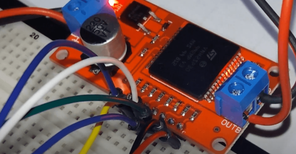
- Based on VNH3ASP30 chip;
- Number of channels: 2;
- Type: H-bridge;
- Load current: Up to 6 A without cooling, up to 14 A with cooling;
- Maximum pulse current up to 30 A;
- Idle current: up to 100 mA;
- Protection against reverse current;
- Capable of reading load current;
- Operating temperature -40° to 302°F (-40° to 150°C);
- Overheat protection;
- PWM up to 20 kHz.
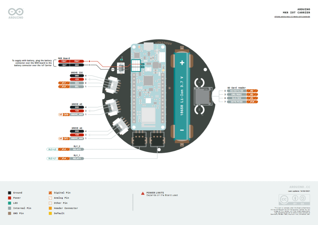
Arduino Connection
| Arduino Outputs |
Monster Moto Shield Outputs |
| A0 |
A1 B1 key status |
| A1 |
A2 B2 key status |
| A2 |
analog output of the current value of the first driver |
| A3 |
analog output of the current value of the second driver |
| 4 |
A2 key control |
| 5 |
PWM control of the first driver |
| 6 |
PWM control of the second driver |
| 7 |
A1 key control |
| 8 |
B1 key control |
| 9 |
B2 key control |
Power
The outputs of the Monster Moto Shield only work from an external 5.5 to 16V power supply, which must be connected to the Vin power inputs.
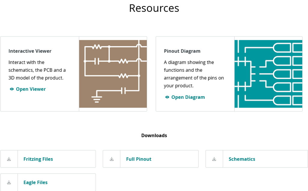
More About Monster Motor Shield
Monster Moto Shield is based on the VNH2SP30 chip, which allows you to control both speed and direction of the connected motors, as well as to block motors and read current consumption, using the analog pins of the Arduino.
Control of DC motors: The functions: motorGo (motor number, direction, PWM) and motorOff (motor number).
- The first DC motor is controlled via outputs 7 (key A1), 8 (key B1) and 5 (PWM). Depending on the state of the keys the motor will rotate in one or the other direction. The PWM controls the speed of the motor.
- The second DC motor is controlled by outputs 4 (key A2), 9 (key B2) and 6 (PWM). Depending on the state of the keys the motor will rotate in one or the other direction. The PWM controls the speed of the motor.
- The direction in the motorGo() function is set by feeding the logic levels to A and B: A=LOW, B=HIGH – motor rotates one way; A=HIGH, B=LOW – motor rotates the other way.
- The speed is set by feeding the PWM signal, the fill factor of which is directly proportional to the speed.
Example (Controlling Two Motors)
#define BRAKEVCC 0 // determine the value of the sharp brake
#define CW 1 //define CW rotation value
#define CCW 2 //define CCW counterclockwise rotation
#define BRAKEGND 3 //define stop value
const uint8_t inApin[2] = {7, 4}; // determine outputs of keys A
const uint8_t inBpin[2] = {8, 9}; // determine outputs of keys B
const uint8_t pwmpin[2] = {5, 6}; // detect PWM outputs
const uint8_t cspin[2] = {A2, A3}; // define current readout pins
const uint8_t enpin[2] = {A0, A1}; // define AB keys state outputs. The keys are opened when pulled to 0.
void setup()
{
Serial.begin(9600);
//transfer the control outputs to the "output" mode
for (int i=0; i<2; i++)
{
pinMode(inApin[i], OUTPUT); // outputs keys A
pinMode(inBpin[i], OUTPUT); // outputs of B keys
pinMode(pwmpin[i], OUTPUT); // PWM outputs
}
// initiate motors off
motorOff(0);
motorOff(1);
}
void loop()
{
motorGo(0, CW, 32); // motorGo(0, CW, 32); // motor 0 clockwise, PWM 17.5%
motorGo(1, CCW, 127); // motorGo(1, CCW, 127); // motor 1 counterclockwise, PWM 50%
delay(3000); // wait 3 seconds, motors are turning
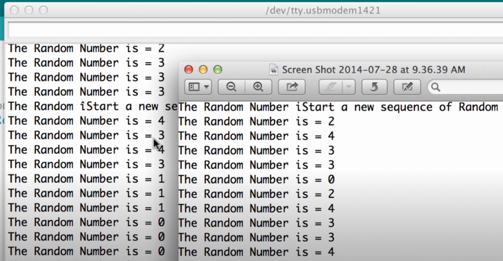
Serial.print(analogRead(cspin[0]));
Serial.print("\t");
Serial.print(analogRead(cspin[1]));
delay(3000);
//convert the output of the state of motor keys 1 to the mode "output":
pinMode(enpin[1], OUTPUT);
// switch off motor 1:
digitalWrite(enpin[1], LOW);
// for three seconds:
delay(3000);
// turn motor 1 on,
// switching the key state output to "input" mode:
pinMode(enpin[1], INPUT);
delay(3000);
motorGo(0, BRAKEVCC, 32); // bring motorGo(0, BRAKEVCC, 32); // bring motor 0 to the "brake" mode
motorGo(1, BRAKEGND, 32); // stop motor 1 in mode "off
while(true); //the script doesn't execute
}
// function to turn off the motor:
void motorOff(int motor)
{
for (int i=0; i<2; i++)
{
digitalWrite(inApin[i], LOW);
digitalWrite(inBpin[i], LOW);
}
analogWrite(pwmpin[motor], 0);
}
// motor on function:
void motorGo(uint8_t motor, uint8_t direct, uint8_t pwm)
{
// if motor number is correct:
if (motor <= 1)
{
// if direct is the same as the directional value:
{ if (direct <= 3)
{
// if motor direction is clockwise or smooth stop,
// set the corresponding values of key A of the selected motor:
if (direct <=1)
digitalWrite(inApin[motor], HIGH);
else
digitalWrite(inApin[motor], LOW);
// if the motor direction is clockwise or sharp stop,
// set the corresponding values of the key B of the selected motor:
if ((direct==0)||(direct==2))
digitalWrite(inBpin[motor], HIGH);
else
digitalWrite(inBpin[motor], LOW);
//set PWM of the selected motor
analogWrite(pwmpin[motor], pwm);
}
}
}
Description of the motorGo() function
Purpose: motor control;
Syntax: motorGo();
Parameters: motor number (0, 1), direction (CW, CCW, BRAKEVCC, BRAKEGND), PWM (0-255);
Return values: void;
Note: direction can be CW – clockwise, CCW – counterclockwise, BRAKEVCC – stop motor with interlock, BRAKEGND – stop motor without interlock.
Example:
motorGo(0, CCW, 127); // turn on motor 1, counterclockwise, speed 50%
Description of the motorOff() function
Purpose: to stop the motor
Syntax: motorOff();
Parameters: motor number (0, 1)
Returned values: void;
Note: this function also sets PWM value equal to zero of the selected motor
Example:
motorOff(1); // turn off the second motor
FAQ
How do I power my Arduino Motor Shield?
To power your Arduino Motor Shield, you will need to connect it to a DC power supply that provides at least 12V and up to 24V. The shield itself has two screw terminals for connecting the positive and negative wires of the DC power source. Make sure that you use an appropriate voltage range as using too much or too little can damage both your motor shield and any motors connected to it. Once wired in correctly, simply turn on the switch on the board itself or press its enable button (if present) and your Arduino Motor Shield should be ready to go!
Can you connect motor directly to Arduino?
Yes, you can connect a motor directly to an Arduino, but it is not recommended. This is because the current requirements of most DC motors are too high for the Arduino’s pins and could damage them. To safely control a DC motor with an Arduino, you should use an L298 bridge IC as this will provide sufficient current while also protecting your board from damage due to excessive currents. Once connected properly through the bridge IC, you can then send signals from your Arduino code to turn on or off power going into each side of the motor which will cause it to rotate in either direction depending on how that power is applied.
How do I connect my RC motor to my Arduino?
Connecting an RC motor to your Arduino is a relatively simple process. First, you will need to purchase the appropriate components for your project such as an RC motor and a compatible power supply. Then, connect the positive lead of the power supply to one terminal on the motor and connect its negative lead to another terminal on it. Finally, use jumper cables or other connectors that are compatible with your Arduino board in order to link up each of these terminals from both sides – one side connected directly into ground pin (GND) while another side should be linked up with Digital Pin 9 (D9). Once all connections have been made correctly, you can begin controlling and powering your RC Motor using code written in C/C++ language within Arduino IDE software.
How many motors can an Arduino control?
The Arduino Mega 2560 is a powerful microcontroller that can be used to control a variety of motors. It has 14 digital output pins, which can be used to directly control up to 14 stepper motors. However, it is also possible to use port expanders and other devices connected through the I2C bus or SPI interface in order for the Arduino Mega 2560 controller board to control even more than just 14 motors – potentially allowing hundreds of different motor types and configurations. The exact number of additional motor outputs depends on how many port expanders are being added but typically an Arduino Mega 2560 could easily support over 50 different motors without any issue at all.
Can Arduino run brushless motor?
Yes, Arduino can run a brushless motor. This is achieved by connecting the ESC (Electronic Speed Controller) to the Arduino board. The ESC receives signals from the Arduino and converts them into appropriate electrical pulses which are then sent to the brushless motor for controlling its speed and direction of rotation. Furthermore, since most modern brushless motors require 3-phase power supply, an additional power source needs to be connected in order for it to work properly with our setup.
Related Video: Unboxing & Testing Monster Moto Shield 30Amp Motor Driver
Wrapping Up
Using the Monster Moto Shield with an Arduino is a great way to test out different motors and their potential applications. With the correct coding and wiring, this shield provides limitless possibilities for projects. It’s easy to understand why so many makers are turning to the Monster Moto Shield for their projects. Although it may seem daunting at first, using this shield with an Arduino is an achievable task that can open many doors.
The post How to Use a Monster Moto Shield With an Arduino: Epic Guide appeared first on NerdyTechy.