Posts | Comments

Planet Arduino

Archive for the ‘software review’ Category

Introduction

Working with GSM modules and by extension Arduino GSM shields can either be a lot of fun or bring on a migraine. This is usually due to the quality of module, conditions placed on the end user by the network, reception, power supply and more.

Furthermore we have learned after several years that even after following our detailed and tested tutorials, people are having trouble understanding why their GSM shield isn’t behaving. With this in mind we’re very happy to have learned about a free online tool that can be used to test almost every parameter of a GSM module with ease – AT Command Tester. This software is a Java application that runs in a web browser, and communicates with a GSM module via an available serial port.

Initial Setup

It’s simple, just visit http://m2msupport.net/m2msupport/module-tester/ with any web browser that can run Java. You may need to alter the Java security settings down to medium. Windows users can find this in Control Panel> All Control Panel Items  > Java – for example:

Java security settings

Once the security settings have been changed, just visit the URL, click ‘accept’ and ‘run’ in the next dialogue box that will appear, for example:

run Java app

And after a moment, the software will appear:

at command tester

Once you’re able to run the AT Command Tester software, the next step is to physically connect the hardware. If you’re just using a bare GSM module, a USB-serial adaptor can be used for easy connection to the PC. For Arduino GSM shield users, you can use the Arduino as a bridge between the shield and PC, however if your GSM shield uses pins other than D0/D1 for serial data transmission (such as our SIM900 shield) then you’ll need to upload a small sketch to bridge the software and hardware serial ports, for example:

//Serial Relay – Arduino will patch a serial link between the computer and the GPRS Shield
//at 19200 bps 8-N-1 Computer is connected to Hardware UART
//GPRS Shield is connected to the Software UART

#include <SoftwareSerial.h>

SoftwareSerial mySerial(7,8); // change these paramters depending on your Arduino GSM Shield

void setup()
{
  Serial.begin(19200);
  //Serial.println(“Begin”);
  mySerial.begin(19200);

}

void loop()
{
  if (mySerial.available())
    Serial.write(mySerial.read());
  if (Serial.available())
    mySerial.write(Serial.read());
}

Using the software

Once you have the hardware connected and the Arduino running the required sketch, run the software – then click “Find ports” to select the requried COM: port, set the correct data speed and click “Connect”. After a moment the software will interrogate the GSM module and report its findings in the yellow log area:

at command tester connected

 As you can see on the left of the image above, there is a plethora of options and functions you can run on the module. By selecting the manufacturer of your GSM module form the list, a more appropriate set of functions for your module is displayed.

When you click a function, the AT command sent to the module and its response is shown in the log window – and thus the magic of this software. You can simply throw any command at the module and await the response, much easier than looking up the commands and fighting with terminal software. You can also send AT commands in batches, experiment with GPRS data, FTP, and the GPS if your module has one.

To give you a quick overview of what is possible, we’ve made this video which captures us running a few commands on a SIM900-based Arduino shield. If possible, view it in 720p.

Conclusion

Kudos to the people from the M2Msupport website for bringing us this great (and free) tool. It works – so we’re happy to recommend it. And if you enjoyed this article, or want to introduce someone else to the interesting world of Arduino – check out my book (now in a third printing!) “Arduino Workshop”.

visit tronixlabs.com

Have fun and keep checking into tronixstuff.com. Why not follow things on twitterGoogle+, subscribe  for email updates or RSS using the links on the right-hand column, or join our forum – dedicated to the projects and related items on this website. Sign up – it’s free, helpful to each other –  and we can all learn something.
Oct
25

Introduction

After helping many people get started with the world of Arduino and electronics,  we still find a small percentage of people who are turned off by the concept of programming or have trouble breaking larger tasks into smaller ones with regards to writing algorithms for their code/sketch.

So after being introduced to a new graphical programming tool called “Ardublock“, we were excited about the possibilities wanted to share it with our readers. Ardublock provides a truly graphical and non-coding solution to controlling an Arduino, that is an open-source product and thus free to download and try for yourself.

Installation

Ardublock is a Java application that runs from inside the Arduino IDE, which can be downloaded from here. It’s only one file, that needs to be placed in a new folder in the Arduino IDE. The folder names must be the same as shown below:

ardublock installation folder

Once you’ve copied the file, simply open the Arduino IDE and select Ardublock from the Tools menu:

arduino ide tools menu ardublockFrom which point a new window appears – the Ardublock “development environment”:

ardublock development environment

 Using Ardublock

It’s quite simple – you simply select the required function from the menu on the left and drag it into the large area on the right. For a quick example where we blink the onboard LED on and off – watch the following video:


The following image is the screen capture of the program from the video:

ardublock LED Blink

As you can see the “blocks” just fit together, and parameters can be changed with the right mouse button. After a few moments experimenting with the Ardublock software you will have the hang of it in no time at all.

And thus you can demonstrate it to other people and show them how easy it is. And there is much more than just digital output controls, all the functions you’re used to including I2C, variables, constants, servos, tone and more are available.

The only technical thing you need to demonstrate is that the Arduino IDE needs to stay open in the background – as once you have finished creating your program, Ardublock creates the required real Arduino sketch back in the IDE and uploads it to the board.

This is also a neat function – the user can then compare their Ardublock program against the actual sketch, and hopefully after a short duration the user will have the confidence to move on with normal coding.

Conclusion

Ardublock provides a very simple method of controlling an Arduino, and makes a great starting point for teaching the coding-averse, very young people or the cognitively-challenged. It’s open source, integrates well with the official IDE and works as described – so give it a go.

And if you enjoyed this review, or want to introduce someone else to the interesting world of Arduino – check out my book (now in a third printing!) “Arduino Workshop” from No Starch Press.

tronixstuff

In the meanwhile have fun and keep checking into tronixstuff.com. Why not follow things on twitterGoogle+, subscribe  for email updates or RSS using the links on the right-hand column? And join our friendly Google Group – dedicated to the projects and related items on this website. Sign up – it’s free, helpful to each other –  and we can all learn something.

The post Review – “Ardublock” graphical programming for Arduino appeared first on tronixstuff.

Introduction

As a beginner in the world of electronics, sooner or later you’ll want to make a more permanent project than what can be constructed on the solderless breadboard. It’s easy to say “make your own PCBs” – however this can introduce a steep learning curve, not to mention the cost and time involved in waiting for PCBs to arrive – and hoping they’re correct. Thus for many people a happy medium is transferring prototype circuits over to stripboard – it’s really cheap (check ebay), you can keep various sizes on hand, and it’s quick.

However planning more complex circuits can be difficult – so it would be much easier with the use of a software design tool. Which brings us to the subject of our review – the Lochmaster v4.0 software from Abacom. It’s an incredibly easy to use developer’s tool for strip board projects. No more loose pieces of graph paper, soldering parts “one row too far over”, or lost design plans – you can now design stripboard projects efficiently and with ease.

Installation

Available for all versions of Windows from XP to 8, Lochmaster is less than ten megabytes and is distributed electronically after purchase – so backup your installation file when received. Otherwise it’s a quick install, you don’t need any extra framework software and due to the size will run well on less-specified machines. Although we have screen shots in the review below, you can download a trial version - so it won’t cost you anything to check it out yourself.

Designing your circuits

Once installed, opening Lochmaster for the first time you’re presented with a blank example of stripboard ready for your components:

Lochmaster

However you can also use different types of prototyping board, such as varieties with all holes, edge connectors, mounting holes, different copper directions – or even make your own board to match a preferred style. Boar dimensions can be displayed in measurement units as well as “holes”. Then it’s a simple matter of selecting a part library from the drop-down list on the left of the window. For example, to add a 555 timer (which is an 8-pin DIL part) select the “ICs” library, click on the 8-pin enclosure and the following window appears, prompting you to fill out the appropriate details such as label, type etc:

Lochmaster 555

… then you can drop the 555 on the board. It then becomes an object which can be dragged around and placed where you need it. You can also create and modify the component libraries, and also create your own custom parts.

At that point, you might want to cut the tracks on the other side of the board. By clicking the “turn around” button the menu bar, you’re presented with the bottom of the board. Using the “add/split” button on the vertical toolbar between the library and the board, you can then virtually cut the tracks, for example:

lochmaster

You can also see the rounded circles which represent solder joints. After a few minutes we found dragging and dropping components onto the board very simple, and with the turn-around button you can easily flip sides until the placement looks good. After placing components, running the necessary links or wires is simple with the “draw jumper wire” tool. They can run in any direction, and also have corners, for example:

Lochmaster wires

You can also adjust the colours and thickness of the wires,  and of course can also be placed on the other side of the board – just flip it around and place the wires. After wiring things up and getting to the stage when you’re ready to build – you can test the connections to ensure you haven’t mis-counted holes or tracks. Using the “Test mode” tool you can click on tracks and the sections that are electrically connected to the point with the cursor are all highlighted – for example if you click on the point marked by the black arrow below, the connected tracks are highlighted:

lochmaster test

If you don’t like the 3D-rendered components, you can also work with normal 2D in colour or black and white:

lochmaster 2D

For final quality-control, you can also review the project at any time with “X-ray” view, which shows an outline of the parts on the other side, for example when looking at the bottom of the board, turning on X-ray results with:

Lochmaster xray

You can also generate component lists, which are great for documentation or simply making up a shopping list. It can be exported to .xls or text file, for example:

lochmaster list

And then you can export your project as an image (.jpg or .bmp), HPGL machine file – and print out both sides to serve as an assembly guide. There is also standalone file-viewer software, so you can share your designs with others who haven’t got the full Lochmaster software installed.

Example project

After experimenting with Lochmaster for a short while, we decided to test using it with a real project that a beginner might assemble. For example, a square wave oscillator from an old Talking Electronics magazine (click image for larger version):

square wave oscillator

Nothing too complex, but a useful tool for anyone experimenting with electronics. It’s a 555 astable with six different RC values which allows you to select from 1, 10, 100, 1 k, 10 k and 100 kHz outputs. The first step is to gather all the components together, so you know the widths and number of holes each needs on the stripboard:

lochmaster_components

The next step is to measure the board, as you can enter the dimensions via Board>Edit board layout… into Lochmaster to avoid having excess space in the design plan. Then after consulting the schematic and the single-layer PCB layout from the magazine, it’s a simple matter of placing the parts onto the virtual board after checking how the fit in on the real thing:

osciillator top

… and the flip-side:

oscillator bottom

Not a work of art – but it works.  (We didn’t fit the 100 kHz setting, as the capacitor wasn’t in stock). And that’s the neat thing – you can experiment with placement until you’re happy, then double-check connections before soldering. You might find even after some planning, that you may deviate from the plan. Fair enough, but just double-check what you’re doing. And a short while later, the results, top and bottom:

oscillator PCB top

oscillator PCB bottom

Conclusion

If you’re a beginner and don’t have the time, money and patience to design your own PCBs – Lochmaster is ideal. It’s a neater way to visualise physical circuits, as well as filing and sharing them with others.   To order your own copy, get the trial version, or if you have any questions please contact Abacom. Full-sized images of the screen-shots can be found on flickr. And if you made it this far – check out my new book “Arduino Workshop” from No Starch Press.

In the meanwhile have fun and keep checking into tronixstuff.com. Why not follow things on twitterGoogle+, subscribe  for email updates or RSS using the links on the right-hand column? And join our friendly Google Group – dedicated to the projects and related items on this website. Sign up – it’s free, helpful to each other –  and we can all learn something.

[Note - Lochmaster software license was a promotional consideration from Abacom]

The post Rapid stripboard prototyping made easy with Lochmaster appeared first on tronixstuff.

Introduction

When the time comes to capture data from a microcontroller-based project, or control an embedded project via a PC – the thought of writing the appropriate PC software can give some people a headache. Or if you’re an Arduino or other development board user and are frustrated with the Serial Monitor box – where do you go? These problems and many more can be solved by using the Megunolink Pro software that’s the subject of this review.

From the Megunolink website,

MegunoLink Pro is a tool designed to aid embedded electronics designers. MegunoLink provides a set of tools to help visualize serial data, it is made up of a set of visualizers that each have a unique function and any number of them can be utilized at once. With these visualizers and our functional tabbed and docked interface you can create a full control center for your embedded project. Plot, log and monitor serial streams from both hardwired, bluetooth, and network based (UDP) devices.

The user interface allows for a completely customized layout with many different visualisers displaying information at once. Perfect for developing exciting new microcontroller based designs. Data streams go from hard to follow serial messages to easy to interpret tables and interactive plots. The interface panel allows you to set up custom GUI elements that let you take control of your device from the comfort of your PC screen.

Phil from Megunolink gives us a quick demonstration in the following video:

Installation

Getting Megunolink running takes around ten minutes. You’ll need a recent PC running Windows of some variety (XP/ 2003/Vista/Win7/8) and also .NET Framework v4.0. You can download a trial Pro version which operates for seven days – at which point you can use the “lite” version or purchase a Pro license. The Megunolink team have given our readers a discount on the personal version, use the coupon code “TROMLP” for 30% off.

Operation

Using Megunolink is quite simple, even though there’s a whole pile of functions. From the home page there’s a variety of documentation for all of the software features, so you can get started very quickly. You can simply capture all output from the serial line and have it saved to a text file (and with a time/date stamp, which removes the need for a RTC in the hardware) – something which seems quite simple but not done with the Arduino IDE:

rtccapture

Furthermore there is an “upload monitor” in Megunolink – which can automatically disconnect from the COM: port used by an Arduino when you need to upload a new sketch, then reconnect afterward. This saves a lot of to-and-fro between the two programs when adjusting code.

The key to analysing data from the microcontroller is to insert text notes in the serial output, which are then interpreted by Megunolink for display purposes. For example, if you have your MCU code send labels with the data, Megunolink can then sort these out into channels and graph the data, for example:

timeplot_screencapture

An example Arduino sketch is provided to demonstrate this, and it translates to other development platforms. Another great feature is the ability to create a graphical user interface for projects connected to the PCB. You design the GUI which can include buttons, sliders and numeric fields, for example:

controls

… and each of which send values of your choice to the device via USB. Then it’s a simple matter of coding your device to respond to the serial commands.

Real-time mapping

As mentioned in the video above, there’s also mapping support – your hardware sends GPS coordinates and they’re displayed in a real-time window:

mapping

Arduino programming

There’s also an interface to allow programming of an Arduino with .hex files via Megunolink. Currently it can work with the ATmega328, -2560, and with an external programmer -328P and -644 microcontrollers.

Conclusion

Once again Megunolink has proven to be a useful piece of software. It gives you a friendly and powerful connection to all the data from your microcontroller, and also a simple GUI for control via serial. So test it for yourself, it won’t cost you anything for the trial version. And if you like it – don’t forget about the tronixstuff.com discount on the personal version - use the coupon code ”TROMLP” for 30% off. Finally, if you have any questions please contact Megunolink. And if you made it this far – check out my new book “Arduino Workshop” from No Starch Press.

In the meanwhile have fun and keep checking into tronixstuff.com. Why not follow things on twitterGoogle+, subscribe  for email updates or RSS using the links on the right-hand column? And join our friendly Google Group – dedicated to the projects and related items on this website. Sign up – it’s free, helpful to each other –  and we can all learn something.

[Note - Megunolink Pro software license was a promotional consideration]


The post Visualise microcontroller data with Megunolink Pro appeared first on tronixstuff.

Introduction

In the same manner as their MSP430 development board, Texas Instruments also have another LaunchPad board with their powerful Stellaris LM4F120H5QR microcontroller. It’s an incredibly powerful and well-featured MCU – which offers an 80 MHz, 32-bit ARM Cortex-M4 CPU with floating point, 256 Kbytes of 100,000 write-erase cycle FLASH and many peripherals such as 1MSPS ADCs, eight UARTs, four SPIs, four I2Cs, USB & up to 27 timers, some configurable up to 64-bits.

That’s a bucket of power, memory and I/O for not much money – you can get the LaunchPad board for around $15. This LaunchPad has the in-circuit debugger, two user buttons, an RGB LED and connectors for I/O and shield-like booster packs:

and the other side:

However the good news as far as we’re concerned is that you can now use it with the Energia Arduino-compatible IDE that we examined previously. Before rushing out to order your own Stellaris board, install Energia and examine the available functions and libraries to make sure you can run what you need. And if so, you’re set for some cheap Arduino power.

Installation

Installation is simple, just get your download from here. If you’re running Windows 7 – get the USB drivers from here. When you plug your LaunchPad into the USB for the first time, wait until after Windows attempts to install the drivers, then install drivers manually after download via Device manager … three times (JTAG, virtual serial port and DFU device). Use the debug USB socket (and set the switch to debug) when installing and uploading code. If you get the following warning from Windows, just click “Install this driver software anyway”:

Once the drivers are installed, plug in your LaunchPad, wait a moment – then run Energia. You can then select your board type and serial port just like the Arduino IDE. Then go ahead and upload the “blink” example…

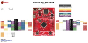
Awesome – check out all that free memory space. In the same manner as the MSP430, there are some hardware<>sketch differences you need to be aware of. For example, how to refer to the I/O pins in Energia? A map has been provided for front:

… and back:

As you can imagine, the Stellaris MCUs are different to an AVR, so a lot of hardware-specific code doesn’t port over from the world of Arduino. One of the first things to remember is that the Stellaris is a 3.3V device. Code may or may not be interchangeable, so a little research will be needed to match up the I/O pins and rewrite the sketch accordingly. For example, instead of digital pins numbers, you use PX_Y - see the map above. So let’s say you want to run through the RGB LED… consider the following sketch:

int wait = 500;
void setup() 
{ 
 // initialize the digital pin as an output.
 pinMode(PF_1, OUTPUT); // red 
 pinMode(PF_3, OUTPUT); // green
 pinMode(PF_2, OUTPUT); // blue
}
void loop() 
{
 digitalWrite(PF_1, HIGH); 
 delay(wait); 
 digitalWrite(PF_1, LOW); 
 digitalWrite(PF_3, HIGH); 
 delay(wait); 
 digitalWrite(PF_3, LOW); 
 digitalWrite(PF_2, HIGH); 
 delay(wait); 
 digitalWrite(PF_2, LOW); 
}

Which simply blinks the red, green and blue LED elements in series. Using digital inputs is in the same vein, and again the buttons are wired so when pressed they go LOW. An example of this in the following sketch:

void setup() 
{ 
 // initialize the digital pins
 pinMode(PF_1, OUTPUT); // red 
 pinMode(PF_3, OUTPUT); // green
 pinMode(PF_2, OUTPUT); // blue

 pinMode(PF_4, INPUT_PULLUP); // left - note _PULLUP
 pinMode(PF_0, INPUT_PULLUP); // right - note _PULLUP 
}
void blinkfast() 
{
 for (int i=0; i<10; i++)
 {
 digitalWrite(PF_1, HIGH); 
 delay(250); 
 digitalWrite(PF_1, LOW); 
 digitalWrite(PF_3, HIGH); 
 delay(250); 
 digitalWrite(PF_3, LOW); 
 digitalWrite(PF_2, HIGH); 
 delay(250); 
 digitalWrite(PF_2, LOW); 
 }
}
void blinkslow() 
{
 for (int i=0; i<5; i++)
 {
 digitalWrite(PF_1, HIGH); 
 delay(1000); 
 digitalWrite(PF_1, LOW); 
 digitalWrite(PF_3, HIGH); 
 delay(1000); 
 digitalWrite(PF_3, LOW); 
 digitalWrite(PF_2, HIGH); 
 delay(1000); 
 digitalWrite(PF_2, LOW); 
 }
}
void loop()
{
 if (digitalRead(PF_4)==LOW) { blinkslow(); }
 if (digitalRead(PF_0)==LOW) { blinkfast(); }
}

And for the non-believers:

Where to from here? 

Sometimes you can be platform agnostic, and just pick something that does what you want with the minimum of time and budget. Or to put it another way, if you need a fast CPU and plenty of space but couldn’t be bothered don’t have time to work with Keil, Code Composer Studio, IAR etc – the Energia/Stellaris combination could solve your problem. There’s a growing Energia/Stellaris forum, and libraries can be found here. At the time of writing we found an I2C library as well.

However to take full advantage of the board, consider going back to the TI tools and move forward with them. You can go further with the tutorials and CCS etc from Texas Instruments own pages.

In the meanwhile have fun and keep checking into tronixstuff.com. Why not follow things on twitterGoogle+, subscribe  for email updates or RSS using the links on the right-hand column? And join our friendly Google Group – dedicated to the projects and related items on this website. Sign up – it’s free, helpful to each other –  and we can all learn something.


Introduction

In the same manner as their MSP430 development board, Texas Instruments also have another LaunchPad board with their powerful Stellaris LM4F120H5QR microcontroller. It’s an incredibly powerful and well-featured MCU – which offers an 80 MHz, 32-bit ARM Cortex-M4 CPU with floating point, 256 Kbytes of 100,000 write-erase cycle FLASH and many peripherals such as 1MSPS ADCs, eight UARTs, four SPIs, four I2Cs, USB & up to 27 timers, some configurable up to 64-bits.

That’s a bucket of power, memory and I/O for not much money – you can get the LaunchPad board for around $15. This LaunchPad has the in-circuit debugger, two user buttons, an RGB LED and connectors for I/O and shield-like booster packs:

and the other side:

However the good news as far as we’re concerned is that you can now use it with the Energia Arduino-compatible IDE that we examined previously. Before rushing out to order your own Stellaris board, install Energia and examine the available functions and libraries to make sure you can run what you need. And if so, you’re set for some cheap Arduino power.

Installation

Installation is simple, just get your download from here. If you’re running Windows 7 – get the USB drivers from here. When you plug your LaunchPad into the USB for the first time, wait until after Windows attempts to install the drivers, then install drivers manually after download via Device manager … three times (JTAG, virtual serial port and DFU device). Use the debug USB socket (and set the switch to debug) when installing and uploading code. If you get the following warning from Windows, just click “Install this driver software anyway”:

Once the drivers are installed, plug in your LaunchPad, wait a moment – then run Energia. You can then select your board type and serial port just like the Arduino IDE. Then go ahead and upload the “blink” example…

stellarisblink

Awesome – check out all that free memory space. In the same manner as the MSP430, there are some hardware<>sketch differences you need to be aware of. For example, how to refer to the I/O pins in Energia? A map has been provided for front:

stellarpad-e28094-pins-maps1

… and back:

stellarpad-back-e28094-pins-maps1

As you can imagine, the Stellaris MCUs are different to an AVR, so a lot of hardware-specific code doesn’t port over from the world of Arduino. One of the first things to remember is that the Stellaris is a 3.3V device. Code may or may not be interchangeable, so a little research will be needed to match up the I/O pins and rewrite the sketch accordingly. For example, instead of digital pins numbers, you use PX_Y - see the map above. So let’s say you want to run through the RGB LED… consider the following sketch:

int wait = 500;
void setup() 
{ 
 // initialize the digital pin as an output.
 pinMode(PF_1, OUTPUT); // red 
 pinMode(PF_3, OUTPUT); // green
 pinMode(PF_2, OUTPUT); // blue
}
void loop() 
{
 digitalWrite(PF_1, HIGH); 
 delay(wait); 
 digitalWrite(PF_1, LOW); 
 digitalWrite(PF_3, HIGH); 
 delay(wait); 
 digitalWrite(PF_3, LOW); 
 digitalWrite(PF_2, HIGH); 
 delay(wait); 
 digitalWrite(PF_2, LOW); 
}

Which simply blinks the red, green and blue LED elements in series. Using digital inputs is in the same vein, and again the buttons are wired so when pressed they go LOW. An example of this in the following sketch:

void setup() 
{ 
 // initialize the digital pins
 pinMode(PF_1, OUTPUT); // red 
 pinMode(PF_3, OUTPUT); // green
 pinMode(PF_2, OUTPUT); // blue

 pinMode(PF_4, INPUT_PULLUP); // left - note _PULLUP
 pinMode(PF_0, INPUT_PULLUP); // right - note _PULLUP 
}
void blinkfast() 
{
 for (int i=0; i<10; i++)
 {
 digitalWrite(PF_1, HIGH); 
 delay(250); 
 digitalWrite(PF_1, LOW); 
 digitalWrite(PF_3, HIGH); 
 delay(250); 
 digitalWrite(PF_3, LOW); 
 digitalWrite(PF_2, HIGH); 
 delay(250); 
 digitalWrite(PF_2, LOW); 
 }
}
void blinkslow() 
{
 for (int i=0; i<5; i++)
 {
 digitalWrite(PF_1, HIGH); 
 delay(1000); 
 digitalWrite(PF_1, LOW); 
 digitalWrite(PF_3, HIGH); 
 delay(1000); 
 digitalWrite(PF_3, LOW); 
 digitalWrite(PF_2, HIGH); 
 delay(1000); 
 digitalWrite(PF_2, LOW); 
 }
}
void loop()
{
 if (digitalRead(PF_4)==LOW) { blinkslow(); }
 if (digitalRead(PF_0)==LOW) { blinkfast(); }
}

And for the non-believers:

Where to from here? 

Sometimes you can be platform agnostic, and just pick something that does what you want with the minimum of time and budget. Or to put it another way, if you need a fast CPU and plenty of space but couldn’t be bothered don’t have time to work with Keil, Code Composer Studio, IAR etc – the Energia/Stellaris combination could solve your problem. There’s a growing Energia/Stellaris forum, and libraries can be found here. At the time of writing we found an I2C library as well.

However to take full advantage of the board, consider going back to the TI tools and move forward with them. You can go further with the tutorials and CCS etc from Texas Instruments own pages.

In the meanwhile have fun and keep checking into tronixstuff.com. Why not follow things on twitterGoogle+, subscribe  for email updates or RSS using the links on the right-hand column? And join our friendly Google Group – dedicated to the projects and related items on this website. Sign up – it’s free, helpful to each other –  and we can all learn something.

The post Exploring the TI Stellaris platform with Energia Arduino-compatible IDE appeared first on tronixstuff.

Jun
27

Improving Arduino to PC Interactions with MegunoLink

arduino, capture, connection, data, interaction, logging, megunolink, serial, software review Comments Off on Improving Arduino to PC Interactions with MegunoLink 

Introduction

Through a colleague I was introduced to a new piece of software for the Windows environment which comprises of useful tools that interact with an Arduino-style board (or other MCU with serial data). The software is called MegunoLink, from BlueLeafSoftware in New Zealand. Megunolink has many useful features, and we’ll run through them briefly in this article. They include:

  • Serial port monitoring – that doesn’t reset the MCU
  • The ability to capture serial port data to a text file
  • A tool to graph formatted data sent from the Arduino in real time
  • “George” the serial monkey! (see below)
  • Enable building Arduino projects using ATMEL AVRstudio
  • And Megunolink can also act as a graphical interface for AVRdude to upload compiled code to an Arduino

Installation was simple and straightforward. The installation is only ~1.5 megabytes and not taxing at all. We only have a Windows 7 64-bit machine, so haven’t tested this in emulation under MacOS or Linux. Before moving ahead, note that the software is free. However the developers do ask for a US$10 donation, and if you use the software more than once this is a very fair amount to pay for such a featured piece of software. Now for a look at each of the features.

Serial Data monitoring

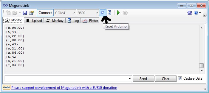
As with the Serial Monitor in the Arduino IDE, you can monitor the data from the Arduino, and also send it back through the serial line. Just click the ‘Monitor’ tab and you’re set, for example:

However unlike the Arduino IDE, opening the monitor does not reset the Arduino. But if you do need to perform a reset, a button on the toolbar is provided as shown below:

Capturing Serial Data to a file

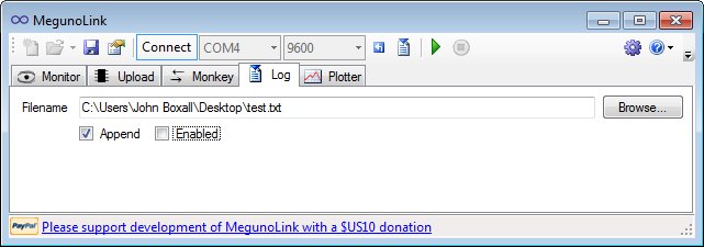
Very useful indeed, much quicker than dumping data to a microSD card and then bringing it back to the PC. Just click the ‘Log’ tab, specify a file location and name, then click ‘Enabled’, for example:

You can also append data to an existing text file. When creating the output format in your Arduino sketch, be mindful to have separators such as commas or colons – which make it much easier to delimit the data once imported into a spreadsheet or database application.

Plotting and Graphing Serial Data

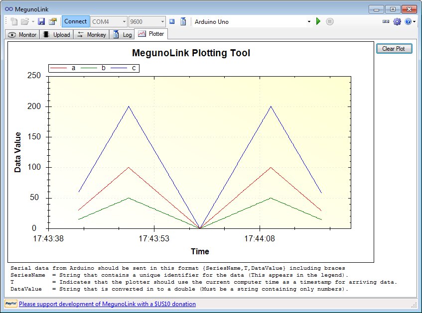
Plotting data to a graph is very simple. You simply format the data you’d like to plot using Serial.write commands, and Megunolink takes care of the rest – just click the ‘Plotter’ tab and you’re off.  The data must be formatted as such:

{a, T, b}

Where ‘a’ is the name of the series. T tells MegunoLink to plot the actual real time, and b is the data as a number in string form. Here is a very simple example:

void setup()
{
 Serial.begin(9600);
}
int a=0;
float b,c;
void loop()
{
 for (int a=0; a<100; a++)
 {
 b=a/2;
 c=a*2;
 Serial.print("{a,T,"); 
 Serial.print(a);
 Serial.println("}");
 Serial.print("{b,T,");
 Serial.print(b);
 Serial.println("}"); 
 Serial.print("{c,T,");
 Serial.print(c);
 Serial.println("}"); 
 delay(100);
 }
 for (int a=100; a>0; --a)
 {
 b=a/2;
 c=a*2;
 Serial.print("{a,T,"); 
 Serial.print(a);
 Serial.println("}");
 Serial.print("{b,T,");
 Serial.print(b);
 Serial.println("}"); 
 Serial.print("{c,T,");
 Serial.print(c);
 Serial.println("}"); 
 delay(100);
 }
}

which resulted with:

Here is another example, it is the “SendSineCurve” sketch from the Arduino Graphing library:

You can always save the graph as an image in the usual formats as well as in .emf vector image file format.

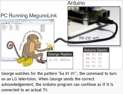
“George” the Serial Monkey

This is a serial protocol simulator tool which is useful for testing the control of serial-based devices. You can setup George so that it listens for a particular pattern in the serial output from an Arduino – and then sends back a response of your choice to the Arduino. For example:

For a more detail explanation and detail tutorial on how to control George, see the MegunoLink website.

Arduino Development with AVR Studio 

Using MegunoLink you can develop Arduino projects with Atmel AVRStudio software. As some people find the Arduino IDE somewhat limiting, this option gives you access to the more programmer-friendly Atmel IDE, for example:

Although there is a small amount of tasks to make this possible, it is straightforward to do so, and an easy to follow tutorial has been provided at the MegunoLink website.

Upload compiled .HEX files to Arduino

For those using avrdude to upload compiled .hex files to an Ardiuno, you can also do this using the GUI MegunoLink interface. This is also used for uploading the compiled files generated in AVRStudio, for example:

As with all the other MegunoLink features – there is a relevant tutorial available on the website.

Conclusion

MegunoLink works well, is easy to use, and the price is right. It has to be the simplest tool available for plotting data from a microcontroller, or capturing it to a file without any extra hardware. So download it and give it a try, it won’t cost you anything and I’m sure you will find a use for it in the near future. And remember – if you’re using MegunoLink, please consider making a donation towards the development of further versions. Thanks to Freetronics for the use of their top-notch Arduino-compatible hardware.

In the meanwhile have fun and keep checking into tronixstuff.com. Why not follow things on twitterGoogle+, subscribe  for email updates or RSS using the links on the right-hand column? And join our friendly Google Group – dedicated to the projects and related items on this website. Sign up – it’s free, helpful to each other –  and we can all learn something.


Jun
27

Introduction

Through a colleague I was introduced to a new piece of software for the Windows environment which comprises of useful tools that interact with an Arduino-style board (or other MCU with serial data). The software is called MegunoLink, from BlueLeafSoftware in New Zealand. Megunolink has many useful features, and we’ll run through them briefly in this article. They include:

  • Serial port monitoring – that doesn’t reset the MCU
  • The ability to capture serial port data to a text file
  • A tool to graph formatted data sent from the Arduino in real time
  • “George” the serial monkey! (see below)
  • Enable building Arduino projects using ATMEL AVRstudio
  • And Megunolink can also act as a graphical interface for AVRdude to upload compiled code to an Arduino

Installation was simple and straightforward. The installation is only ~1.5 megabytes and not taxing at all. We only have a Windows 7 64-bit machine, so haven’t tested this in emulation under MacOS or Linux. Before moving ahead, note that the software is free. However the developers do ask for a US$10 donation, and if you use the software more than once this is a very fair amount to pay for such a featured piece of software. Now for a look at each of the features.

Serial Data monitoring

As with the Serial Monitor in the Arduino IDE, you can monitor the data from the Arduino, and also send it back through the serial line. Just click the ‘Monitor’ tab and you’re set, for example:

However unlike the Arduino IDE, opening the monitor does not reset the Arduino. But if you do need to perform a reset, a button on the toolbar is provided as shown below:

Capturing Serial Data to a file

Very useful indeed, much quicker than dumping data to a microSD card and then bringing it back to the PC. Just click the ‘Log’ tab, specify a file location and name, then click ‘Enabled’, for example:

You can also append data to an existing text file. When creating the output format in your Arduino sketch, be mindful to have separators such as commas or colons – which make it much easier to delimit the data once imported into a spreadsheet or database application.

Plotting and Graphing Serial Data

Plotting data to a graph is very simple. You simply format the data you’d like to plot using Serial.write commands, and Megunolink takes care of the rest – just click the ‘Plotter’ tab and you’re off.  The data must be formatted as such:

Where ‘a’ is the name of the series. T tells MegunoLink to plot the actual real time, and b is the data as a number in string form. Here is a very simple example:

which resulted with:

Here is another example, it is the “SendSineCurve” sketch from the Arduino Graphing library:

You can always save the graph as an image in the usual formats as well as in .emf vector image file format.

“George” the Serial Monkey

This is a serial protocol simulator tool which is useful for testing the control of serial-based devices. You can setup George so that it listens for a particular pattern in the serial output from an Arduino – and then sends back a response of your choice to the Arduino. For example:

For a more detail explanation and detail tutorial on how to control George, see the MegunoLink website.

Arduino Development with AVR Studio 

Using MegunoLink you can develop Arduino projects with Atmel AVRStudio software. As some people find the Arduino IDE somewhat limiting, this option gives you access to the more programmer-friendly Atmel IDE, for example:

Although there is a small amount of tasks to make this possible, it is straightforward to do so, and an easy to follow tutorial has been provided at the MegunoLink website.

Upload compiled .HEX files to Arduino

For those using avrdude to upload compiled .hex files to an Ardiuno, you can also do this using the GUI MegunoLink interface. This is also used for uploading the compiled files generated in AVRStudio, for example:

As with all the other MegunoLink features – there is a relevant tutorial available on the website.

Conclusion

MegunoLink works well, is easy to use, and the price is right. It has to be the simplest tool available for plotting data from a microcontroller, or capturing it to a file without any extra hardware. So download it and give it a try, it won’t cost you anything and I’m sure you will find a use for it in the near future. And remember – if you’re using MegunoLink, please consider making a donation towards the development of further versions. Thanks to Freetronics for the use of their top-notch Arduino-compatible hardware.

In the meanwhile have fun and keep checking into tronixstuff.com. Why not follow things on twitterGoogle+, subscribe  for email updates or RSS using the links on the right-hand column? And join our friendly Google Group – dedicated to the projects and related items on this website. Sign up – it’s free, helpful to each other –  and we can all learn something.

The post Improving Arduino to PC Interactions with MegunoLink appeared first on tronixstuff.


  • Newsletter

    Sign up for the PlanetArduino Newsletter, which delivers the most popular articles via e-mail to your inbox every week. Just fill in the information below and submit.

  • Like Us on Facebook