Posts | Comments

Planet Arduino

Archive for the ‘ATmega328’ Category

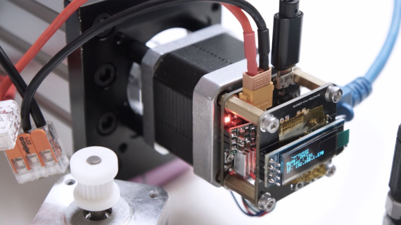
[Neumi] over on Hackaday.IO wanted a simple-to-use way to drive stepper motors, which could be quickly deployed in a wide variety of applications yet to be determined. The solution is named Ethersweep, and is a small PCB stack that sits on the rear of the common NEMA17-format stepper motor. The only physical connectivity, beside the motor, are ethernet and a power supply via the user friendly XT30 connector. The system can be closed loop, with both an end-stop input as well as an on-board AMS AS5600 magnetic rotary encoder (which senses the rotating magnetic field on the rear side of the motor assembly – clever!) giving the necessary feedback. Leveraging the Trinamic TMC2208 stepper motor driver gives Ethersweep silky smooth and quiet motor control, which could be very important for some applications. A rear-facing OLED display shows some useful debug information as well as the all important IP address that was assigned to the unit.

Control is performed with the ubiquitous ATMega328 microcontroller, with the Arduino software stack deployed, making uploading firmware a breeze. To that end, a USB port is also provided, hooked up to the uC with the cheap CP2102 USB bridge chip as per most Arduino-like designs. The thing that makes this build a little unusual is the ethernet port. The hardware side of things is taken care of with the Wiznet WS500 ethernet chip, which implements the MAC and PHY in a single device, needing only a few passives and a magjack to operate. The chip also handles the whole TCP/IP stack internally, so only needs an external SPI interface to talk to the host device.

Talking about firmware for a moment, to ease deployment, the network configuration is handled by DHCP, although some control over MAC address assignment is promised for the future. All control is via UDP over ethernet, and again the basic functionality is there, but some niceties such as motor synchronisation and state querying are again subject to further releases. Hardware design is implemented in KiCAD and FreeCAD, with Arduino covering the firmware and host control side in python. You can read all about it on the Ethersweep project GitHub, what is there not to like?

If you thought you’d seen this stepper-mounted driver setup before, you’d be correct, here’s a Hackaday Prize 2017 Entry for a CANBUS controlled driver. We also saw this on Dummy: the obscenely well made robot arm by [Zhihui Jun], which if you missed it, then do circle back and take a look, you won’t regret it!

One of the biggest challenges for wireless sensor networks is that of power. Solar panels usually produce less power than you hoped, especially small ones, and designing super low power circuits is tricky. [Strange.rand] has dropped into the low-power rabbit hole, and is designing a low-cost wireless sensor node that runs on solar power and a supercapacitor.

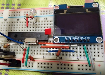
The main components of the sensor node is an ATMega 328P microcontroller running at 4Mhz, RFM69 radio transceiver, I2C temperature/humidity sensor, 1F supercapacitor, and a small solar panel. The radio, MCU, and sensor all run on 1.5-3.6V, but the supercap and solar panel combination can go up to 5.5V. To regulate the power to lower voltage components a low-drop voltage regulator might seem like the simplest solution, but [strange.rand] found that the 3.3V regulator was consuming an additional 20uA or more when the voltage dropped below 3.3V. Instead, he opted to eliminate the LDO, and limit the charging voltage of the capacitor to 3.6V with a comparator-based overvoltage protection circuit. Using this configuration, the circuit was able to run for 42 hours on a single charge, transmitting data once per minute while above 2.7V, and once every three minutes below that.

Another challenge was undervoltage protection. [strange.rand] discovered that the ATmega consumes an undocumented 3-5 mA when it goes into brown-out below 1.8V. The small solar panel only produces 1 mA, so the MCU would prevent the supercapacitor from charging again. He solved this with another comparator circuit to cut power to the other components.

We see challenges like these a lot with environmental sensors and weather stations with smaller solar panels. For communication, low power consumption of a sub-Ghz radio is probably your best bet, but if you want to use WiFi, you can get the power usage down with a few tricks.

Not satisfied with any of the DIY retro computer kits on the market, [Leonardo Leoni] decided to make his own. Built using only the finest through-hole technology and powered by the ATmega328 microcontroller, his diminutive 8-bit computer is easy to build and even easier to develop for. Whether you’re looking to hone your BASIC skills or play some Zork on the bus, this little computer looks like a great project for anyone who has a soft spot for computing’s simpler days.

All things considered, using this diminutive machine looks like it would be relatively pleasant. [Leonardo] is using a common SH1106 OLED display, and there’s a full QWERTY keyboard (with number row) done up with tactile momentary buttons. There’s very few passive components involved in the build, which is sure to be appealing to new players; especially after they’ve finished soldering all those switches to the board.

On the software side, [Leonardo] says he leaned heavily on open source projects to get his machine up and running. Beyond the hardware drivers for things like the display, he specifically calls out the Tiny Basic and Tiny Lisp Computer projects for their code. If small-scale programming isn’t your style, the machine is compatible with the Arduino IDE so you can easily throw something else on it. If you’ve ever dreamed of a QWERTY Arduboy, this might be your chance.

From the way [Leonardo] describes the computer, which he calls the Cobalt 3, we get the impression a commercial kit might be in the cards. We hope the community shows enough interest to make it happen. After all, not everyone was able to make it to Hackaday Belgrade 2018 to get their own pocket retro computer.

We sure wish we’d had a teacher like [Volos Projects]. He built this beautiful circuit sculpture to teach his students how to count in binary and convert it to decimal and hexadecimal. If you don’t already know binary, you get to learn it on DIP switches and a dead-bugged ATMega328 in the video after the break. Lucky you!

Once the students have the hang of entering binary input on the switches, they can practice it on the four-banger calculator. This educational sculpture can also take text input and scroll it, but it takes a bit of work. You have to look up the ASCII value of each character, convert the decimal to binary, and program it in with the switches. There’s one more function on the menu — a one-player PONG game to help the students relax after a long day of flipping switches.

Funny enough, this project came to be after [Volos Projects] came upon the DIP switch in his parts box and wasn’t quite sure what it was called. How great is it that he learned something about this part, and then used that knowledge to build this machine that uses the part to teach others? It’s surely the best fate that parts bin curiosities can hope for.

Don’t have the patience for circuit sculpture? You can make a pretty nice binary calculator with a bit of paper and a lot of compressed air.

Via [r/arduino]

In this era of 4K UHD game console graphics and controllers packed full of buttons, triggers, and joysticks, it’s good to occasionally take a step back from the leading edge. Take a breath and remind ourselves that we don’t always need all those pixels and buttons to have some fun. The LedCade is a μ (micro) arcade game cabinet built by [bobricius] for just this kind of minimalist gaming.

Using just three buttons for input and an 8×8 LED matrix for output, the LedCade can nevertheless play ten different games representing classic genres of retro arcade gaming. And in a brilliant implementation of classic hardware hacking humor, a player starts their game by inserting not a monetary coin but a CR2032 coin cell battery.

Behind the screen is a piezo speaker for appropriately vintage game sounds, and an ATmega328 with Arduino code orchestrating the fun. [bobricius] is well practiced at integrating all of these components as a result of developing an earlier project, the single board game console. This time around, the printed circuit board goes beyond being the backbone, the PCB sheet is broken apart and reformed as the enclosure. With classic arcade cabinet proportions, at a far smaller scale.

If single player minimalist gaming isn’t your thing, check out this head-to-head gaming action on 8×8 LED arrays. Or if you prefer your minimalist gaming hardware to be paper-thin, put all the parts on a flexible circuit as the Arduflexboy does.

The concept of a smartwatch was thrown around for a long time before the technology truly came to fruition. Through the pursuit of miniaturisation, modern smartwatches are sleek, compact, and remarkably capable for their size. Companies such as Apple and Samsung throw serious money into research and development, but that doesn’t mean you can’t create something of your own. [Electronoobs] has done just that, with this Arduino-based smartwatch build.

The brain of the watch is that hacker staple, the venerable ATmega328, most well known for its use in the Arduino Uno and Nano platforms. An FTDI module is used for USB communication, making programming the board a snap. Bluetooth communication is handled by another pre-built module, and a smartphone app called Notiduino handles passing notifications over to the watch.

This is a build that doesn’t do anything crazy or difficult to understand, but simply combines useful parts in a very neat and tidy way. The watch is impressively thin and compact for a DIY build, and has a host of useful functions without going overboard.

We’ve seen other DIY builds in this space, too – such as this ESP8266-based smartwatch. Video after the break.

There’s a school of thought that says that to fully understand something, you need to build it yourself. OK, we’re not sure it’s really a school of thought, but that describes a heck of a lot of projects around these parts.

[Tim] aka [mitxela] wrote kiloboot partly because he wanted an Ethernet-capable Trivial File Transfer Protocol (TFTP) bootloader for an ATMega-powered project, and partly because he wanted to understand the Internet. See, if you’re writing a bootloader, you’ve got a limited amount of space and no device drivers or libraries of any kind to fall back on, so you’re going to learn your topic of choice the hard way.

[Tim]’s writeup of the odyssey of cramming so much into 1,000 bytes of code is fantastic. While explaining the Internet takes significantly more space than the Ethernet-capable bootloader itself, we’d wager that you’ll enjoy the compressed overview of UDP, IP, TFTP, and AVR bootloader wizardry as much as we did. And yes, at the end of the day, you’ve also got an Internet-flashable Arduino, which is just what the doctor ordered if you’re building a simple wired IoT device and you get tired of running down to the basement to upload new firmware.

Oh, and in case you hadn’t noticed, cramming an Ethernet bootloader into 1 kB is amazing. If doing big things in small codespaces floats your boat, check out the winners from our own 1kB challenge.

Speaking of bootloaders, if you’re building an I2C slave device out of an ATtiny85¸ you’ll want to check out this bootloader that runs on the tiny chip.

Some of the entries for the 2017 Coin Cell Challenge have already redefined what most would have considered possible just a month ago. From starting cars to welding metal, coin cells are being pushed way outside of their comfort zone with some very clever engineering. But not every entry has to drag a coin cell kicking and screaming into a task it was never intended for; some are hoping to make their mark on the Challenge with elegance rather than brute strength.

A perfect example is the LiquidWatch by [CF]. There’s no fancy high voltage circuitry here, no wireless telemetry. For this entry, a coin cell is simply doing what it’s arguably best known for: powering a wrist watch. But it’s doing it with style.

The LiquidWatch is powered by an Arduino-compatible Atmega328 and uses two concentric rings of LEDs to display the time. Minutes and seconds are represented by the outer ring of 60 LEDs, and the 36 LEDs of the inner ring show hours. The hours ring might sound counter-intuitive with 36 positions, but the idea is to think of the ring as the hour hand of an analog watch rather than a direct representation of the hour. Having 36 LEDs for the hour allows for finer graduation than simply having one LED for each hour of the day. Plus it looks cool, so there’s that.

Square and round versions of the LiquidWatch’s are in development, with some nice production images of [CF] laser cutting the square version out of some apple wood. The wooden case and leather band give the LiquidWatch a very organic vibe which contrasts nicely with the high-tech look of the exposed PCB display. Even if you are one of the legion that are no longer inclined to wear a timepiece on their wrist, you’ve got to admit this one is pretty slick.

Whether you’re looking to break new ground or simply refine a classic, there’s still plenty of time to enter your project in the 2017 Coin Cell Challenge.


Filed under: Arduino Hacks, clock hacks, contests

Trolling eBay for parts can be bad for your wallet and your parts bin. Yes, it’s nice to be well stocked, but eventually you get to critical mass and things start to take on a life of their own.

This unconventional Arduino-based FM receiver is the result of one such inventory overflow, and even though it may take the long way around to listening to NPR, [Kevin Darrah]’s build has some great tips in it for other projects. Still in the mess-o-wires phase, the radio is centered around an ATmega328 talking to a TEA5767 FM radio module over I²C. Tuning is accomplished by a 10-turn vernier pot with an analog meter for frequency display. A 15-Watt amp drives a pair of speakers, but [Kevin] ran into some quality control issues with the amp and tuner modules that required a little extra soldering as a workaround. The longish video below offers a complete tutorial on the hardware and software and shows the radio in action.

We like the unconventional UI for this one, but a more traditional tuning method using the same guts is also possible, as this retro-radio refit shows.


Filed under: Arduino Hacks, misc hacks


  • Newsletter

    Sign up for the PlanetArduino Newsletter, which delivers the most popular articles via e-mail to your inbox every week. Just fill in the information below and submit.

  • Like Us on Facebook