The NeoRGB is a no-soldering, plug-and-play STEMMA board with a 2mm JST PH connector on one end, and a 5-pin 0.1″ screw terminal block on the other. It can convert standard 800KHz NeoPixel signal using a WS2811F chip to AO3406 N-channel FETs that are high efficiency and can sink a chunk of current – 3 Amps a piece with 50milliOhm Ron!
The Adafruit NeoRGB Stemma guide has everything you need to get started with using this breakout. There’s pages for overview, pinouts, CircuitPython, Arduino and resources for download.
I was intrigued by a recent project I saw that used two LED matrices placed diagonally to create an hourglass. The animated movement of the LEDs seemed a good simulation of the sand particles moving through the hourglass.
As is common, the project emphasized on how the hardware was wired together, which is trivial, without much explanation of its more challenging/interesting software aspects.
Additionally, most of the solutions I saw used an inertial position sensor to determine the position of the matrix, which seemed overkill for the simple functionality required.
So I decided to explore this topic and here is my solution.
Hourglass Basics
Hourglass
An hourglass (also known as a sand clock) is used to measure the passage of time. An hourglass is usually made up of two symmetric glass bulbs connected vertically by a narrow neck through which sand, or other suitable material, goes from the upper to the lower bulb under the action of gravity. The hourglass is turned upside-down to start another timer when all the sand runs into the bottom bulb.
Each hourglass is designed to measure a specific time interval – the time it takes to empty one bulb into the other. This time is regulated by factors that include the amount and size of the sand particles, the bulb size and the neck width.
Hardware Assembly
LED Matrices
The LED matrices are the commonly available 8×8 LED modules controlled by a MAX7219 controller. For this project the matrices with smaller PCBs that fit under the LED module are the best form factor.
Orientation Sensor
To keep things simple the orientation of the matrix is measured by a simple digital input wired to a tilt switch. These small and inexpensive sensors are available in many shapes and sizes, but all work similarly – a digital signal in one orientation and no signal for the opposite orientation, as shown in the figure below.
Internally the switch commonly has a metal ball that moves to make/break the electrical circuit.
This sensor is not able to detect intermediate states (eg, the hourglass on its side) but I am happy to live with that tradeoff compared to a much more expensive inertial sensor.
Hourglass Bezel
For testing purposes, using Fusion 360, I designed and 3D printed an hourglass shaped bezel to hold the 2 modules a jam fit.
This keeps the modules in the correct diagonal orientation with respect to each other and allows me to conveniently rotate the whole device easily.
Software Implementation
The software discussed in this section is available as the MD_MAX72xx_Hourglass example code with the MD_MAX72xx library.
Simulating the Hourglass
When thinking about this closed system, the top bulb can be considered a silo filled with sand with an exit at the bottom. As the sand passes through the neck, the sand particles above the moved particle also move into the void below and this is repeated all the way to the top of the sand reservoir.
As the mechanism is driven by gravity, it can be thought of as the particles trying to minimize their potential energy with respect to the hourglass neck.
Once the sand passes the neck it will fall (again trying to minimize the potential energy with respect to the base of the lower bulb) until it reaches the rest of the sand pile, at which time it will move over the surface of the existing pile trying to find its minimum energy state.
A good proxy for simulating the energy of each particle could be the distance between each particle and the neck/base, as potential energy is related to the height of each particle from the relevant ‘zero energy’ point.
Some Definitions
As these ‘zero energy’ point are points to which the particles are attracted, I decided to call them attractors in the software.
There are four attractors relevant to the simulation, shown in the figure at left, called HIHI, HI, LO, LOLO. When particles are travelling from the top to the bottom bulb, they are initially attracted to the HI attractor (the bottom of the top bulb) and then the LOLO attractor when they pass through the neck.
Conversely when the hourglass is turned over the attractors become the LO and HIHI attractors.
When wiring the matrices together, the module with the HI and HIHI attractor is module 0 (the first in the chain) and the other is module 1. The electrical connections are from the top to the bottom modules, as shown on the left.
Software Structure
There is a relatively simple structure to this software:
Initialization (ie, the setup() function).
Check if hourglass has changed orientation.
At the appropriate time
Moving all the particles in both bulbs
Moving a particle from the upper to the lower bulb if one is ready to drop
Updating the matrices with the new arrangement
We’ll discuss each of these in turn below.
Data Structures and Static Data
Two simple data structures are defined to help manage the simulation.
The first is small container for the row and column coordinates of a LED ‘particle’.
typedef struct
{
  int8_t r, c;
} coord_t;
The next is the definition of a particle, which comprises its coordinates on the display and the attractor that is controlling its motion.
The attractor enumerated type has the values as discussed earlier. The enumerated values are specifically nominated as they are used as the index into an array of constant coordinates for each of the attractors.
Finally, an enumerated type is defined to track the current orientation of the hourglass (ie, the direction in which the particles are flowing due to the action of gravity).
// flow direction for particles (HI->LO or LO->HI)
typedef enum
{
  FLOW_HI2LO,
  FLOW_LO2HI
} flowDirection_t;
Initialization
The particle array is statically initialized when it is declared. As the matrix is on the diagonal corner, this seemed an easier way to get a specific pattern in the top bulb at the start.
The normal hardware initialization happens in setup(), and the display is updated with the starting particle arrangement.
Check Hourglass Orientation
The hourglass orientation is given by a simple digital input from the tilt sensor. When that input changes it needs to be processed into a direction indicator (FLOW_* enumerated value) and a different attractor (ATT_*) for each particle.
For example, if a particle is in the top bulb, travelling FLOW_HI2LO directions, is currently attracted to ATT_HI. Once the flow is reversed (to FLOW_LO2HI) that particle is now attracted to HIHI.
Moving Particles
Particle moves occur periodically, controlled by the total timer duration, 30 seconds for the example code. Given that all the particles need to transition to the next bulb by the end of the period, each time slice is a total time divided by the number of particles.
For each particle, each of the 8 points surrounding the particle need to be tested to see if the particle should move into that location. A particle can move into a new location if:
The location is unoccupied.
The location is within the bounds of the hourglass bulb containing the particle.
The distance to the particle’s attractor is the minimum distance of the current set of potential locations.
The distance between the particle and its attractor is the length of the line segment that connects the two points, given by d=√((r2 – r1)² + (c2 – c1)²). As d is just for comparison the square root is unnecessary and the software uses d².
If two or more points are found to be equal minima, then a random choice is made between them.
Transition Particles
Once all the particles have moved, a special check is made to see if a particle is at the ATT_HI or ATT_LO points (depending on the flow direction).
If one is found, it is moved to the top of the lower bulb if there is no other particle there and its attractor is changed so that it travels to the bottom of the hourglass.
Display Update
The display update clears the display and then redraws all the particles at their current coordinates.
So does it work?
Given the simplicity of the approach and simulation code, the LED hourglass display looks good and works surprisingly well.
I fell into an internet search rabbit hole and came across ‘Drag Racing’ start lights. I had seen references to these on the Arduino forum and they looked interesting enough, and followed well defined rules, to be a relatively simple project for programming practice.
Here’s the result from an afternoon of tinkering.
How do these start lights work?
Drag races are started electronically by a system known as a Christmas tree. A common Christmas tree consists of a column of seven lights for each driver or lane, as well as a set of light beams across the track itself. The light beams are arranged with one set on the starting line, and another set 7 inches behind it.
Each side of the column of lights is the same from the top down:
two blue/white/yellow (it seems to vary) lamps at the top
three amber/yellow lamps
one green lamp
one red lamp
When drivers are preparing to race, they first cross the beams 7 inches behind the starting line. Crossing this beam put the race in pre-staged mode and activates the top bulbs. At this point the tree is activated.
Once pre-staged, drivers roll up 7 inches and cross the second beam on the starting line. Once the first driver activates the bottom (staged) bulbs, the subsequent drivers have 7 seconds to do the same or they are timed out and automatically disqualified.
Once all drivers have crossed the staged sensor, or are timed out, the starting system activates the amber lighting sequence within 1.3 seconds of the last car being staged or being disqualified. The lighting sequence will be different based on the type of tree and race start being used:
A Standard tree lights up each amber light in sequence with a 500 millisecond (ms) delay between them, followed by the green light after another 500 ms delay.
A Professional tree lights up all the amber lights at the same time, followed by the green light after a 400 ms delay.
A Hybrid (or Professional 500) tree, is the same as a professional tree with a 500 ms delay before the green light.
On the activation of the green light the drivers are supposed to start the race.
Leaving the “Staged” line before the green light activates will instantly stop the count down and result in a lighting of the red light and a provisional disqualification of the offending driver.
Software Design
There are 2 things that we need to keep track of for this project.
The first is the racer or racing lane (these are one-to-one so I consider them equivalent). Each race has a number of lanes (usually 2 but in our world potentially more). A lane has a digital device (digital input for us) to show that the vehicle is staged and a similar device to show when the vehicle moves past the start line. A lane/racer also has the attributes of being in a staged and/or foul state.
The second is the set of lights. Each lane has one or more start light trees associated with that lane. There is always one light tree facing the racer but there could be more for crowd/officials. A light tree therefore has an association with a racer and the appropriate lighting circuits.
The logic to progress the lighting sequence is simple to implement as a Finite State Machine that follows the process description above. In my case I also wanted to capture Standard, Professional and Hybrid operating modes within the same code base.
Hardware Implementation
The first decision for the hardware is to decide how the software will be used. I decided that the software was probably most likely to be used for model or radio-controlled cars, so Neopixel (serial RGB) LEDs can be used allowing the system to be implemented with relatively low power requirements. The code logic is, obviously, scalable to larger systems if required by changing the output hardware.
For simplicity I also assumed that digital inputs provide the necessary signals for staging and foul condition. A simple digital is also used as a control to restart the lights sequence. During testing all these digital signals were connected to tact switches.
Software Implementation
The full sketch for this project is available at my code repository.
The first thing to define are the racer and light tree data structures as they form the basis for the rest of the code.
The oneTree_t type defines a tree of lights. The set of neopixel LEDs for a tree is assumed to be consecutive and similar (ie, same order) for all trees. This means that we just need to keep track of the base LED number for each tree and the rest are standard offsets from this base.
// Define the offsets from base for each set of lights
const uint8_t idStaging = 0;            // Staging LED
const uint8_t idStaged = 1;             // Staged LED
const uint8_t idReady[3] = { 2, 3, 4 }; // Ready LED (yellow)
const uint8_t idGo = 5;                 // Go LED (green)
const uint8_t idFoul = 6;               // Fould LED (red)

const uint8_t LED_PER_TREE = 7;         // LEDS in each tree

// Define what we need to keep track of for one tree of lamps
struct oneTree_t
{
  uint8_t idRacer;    // 0 .. NUM_RACERS-1. Racer's tree.
  uint8_t idLEDBase;  // The first led number for this tree
};

// Define the data for all the lamp trees required
// There are only 2 types of trees (one per racer) but these
// may be displayed multiple times (eg, front and back of a
// column, around the park, etc).
// This array defines the number of trees required, which
// racers they 'belong' to and the starting neopixel address
// for the LED_PER_TREE leds for this tree.
// Altogether this is the total number of LEDS that the
// FastLED software has to manage.
oneTree_t display[] =
{
  { 0, 0 },
  { 1, LED_PER_TREE * 1 },
  { 0, LED_PER_TREE * 2 },
  { 1, LED_PER_TREE * 3 },
};
The oneRacer_t type groups the data related to one racer. Input pins are defined for the ‘staged’ and ‘fault’ inputs, and booleans keep track of the staged and foul conditions.
// Define what we need to keep track of for one racer
struct oneRacer_t
{
  uint8_t pinStaged;  // input pin indicates staged when low
  uint8_t pinFoul;    // input pin indicates foul when low
  bool isStaged;      // true if the racer is staged
  bool isFoul;        // true if tree is showing foul
};

// Define the data for all the racers
// One line entry per racer. There are normally only 2
// racers in a drag race but more can be defined if required
// without changes to the software.
oneRacer_t racer[] =
{
  { 4, 5, false, false },
  { 6, 7, false, false },
};

// Derive global constants from this array definition
const uint8_t NUM_RACERS = ARRAY_SIZE(racer);
The different operating modes are implemented through timing differences and some minor code variation. The software will compile to operate in any of the three modes by using the compile time #define TREE_MODE.
// Define the running mode for the tree
// Set 0 = Standard, 1 = Professional or 2 = Hybrid
#ifndef TREE_MODE
#define TREE_MODE 0
#endif

// Set up parameters for different modes
#if TREE_MODE == 0  // Standard Mode
#warning "Compiling for STANDARD TREE"

const uint32_t STAGE_DELAY = 7000; // in milliseconds
const uint32_t READY_DELAY = 1300; // in milliseconds
const uint32_t SET_DELAY = 500;    // in milliseconds
const uint32_t GO_DELAY = 500;     // in milliseconds

#elif TREE_MODE == 1  // Professional Mode
#warning "Compiling for PROFESSIONAL TREE"

const uint32_t STAGE_DELAY = 7000; // in milliseconds
const uint32_t READY_DELAY = 1300; // in milliseconds
const uint32_t SET_DELAY = 0;      // in milliseconds
const uint32_t GO_DELAY = 400;     // in milliseconds

#elif TREE_MODE == 2  // Hybrid Mode
#warning "Compiling for HYBRID TREE"

const uint32_t STAGE_DELAY = 7000; // in milliseconds
const uint32_t READY_DELAY = 1300; // in milliseconds
const uint32_t SET_DELAY = 0;      // in milliseconds
const uint32_t GO_DELAY = 500;     // in milliseconds

#endif
The bulk of the controlling code is in the loop() function, which is a Finite State Machine implemented in a case statement with the following cases defined:
  static enum {
    RESET,        // reset variables for next run
    PRE_STAGE,    // wait for signal to enable tree
    STAGING,      // wait for all lanes to stage or time out
    WAIT_START,   // delay before start sequence
    START_READY,  // yellow light sequence
    START_SET,    // delay before green
    START_GO,     // set green light
    WAIT_RESET,   // sequence ended, waiting for signal to reset
  } curState = RESET;
Natasha Dzurny turned out this really cool project for Element 14. In short, she makes a birthday cake shaped display using flexible LED matrixes. Inspired by Lizzo’s birthday anthem, Natasha decided to make a whole party in the shape of a cake. She started with an Arduino Nano 33it and two LED matrixes and ended […]
Rock/Paper/Scissors (RPS) is a game using simple rules and a circular winning strategy that I thought would be interesting to code. Additionally, there is an element of suspense/anticipation to the game that adds to its enjoyment, and I challenged myself with trying to capture this part of the experience as well.
So, during a few of the many recent rainy days I decided to spend some time seeing what I could do with an Arduino Uno, some tact switches and a few LED matrix modules.
I expect that most readers are familiar with this game, so here is a brief summary of the rules.
RPS is a hand game usually played between two people in which each player simultaneously forms one of three shapes with their hand. These shapes are a closed fist, a flat hand, and a fist with index and middle fingers forming a V (representing rock, paper and scissors respectively).
The game has three possible outcomes – win, draw or loss – based on the following simple rules:
Rock beats scissors (rock ‘breaks’ scissors).
Paper beats rock (paper ‘covers’ rock).
Scissors beats paper (scissors ‘cuts’ paper).
If both players form the same shape the result is a draw.
When the game is played with more than two players, everyone in the group plays their hand as in the two-player game, but the result is determined by the following additional rules:
Everyone plays again if all shapes are the same or all three shapes are shown (ie, 1 shape or 3 shapes are shown).
If only two shapes are showing, the rules for two players are applied to each group’s shape and players in the winning group remain in the game.
When only two players remain, the rules revert to the normal two-player game.
An important aspect of the game experience is the countdown (1, 2, 3 or Ready, Set, Go) before each player simultaneously shows their hand, followed by the quick survey of hands to determine the winner.
Hardware
To keep things really simple, each player has three to select the shape they choose for the next turn (R, P or S). These switches don’t need to be debounced as we are only interested in knowing the switch has been activated. Once this is detected, the player’s turn is complete until the next run of the game. This implementation allows up to four players and so needs 12 switches.
Gameplay is displayed on 8×8 LED modules, one module per player. The displays are connected using the hardware SPI interface and managed by the MD_MAX72xx library.
The photo below shows the setup using my prototyping system (described in this earlier post) connected to an Arduino Uno.
Programming
Breaking it Down
For the purposes of organizing the play sequence, each play session is divided into 3 separate parts.
A Session is the entire sequence from when the processor is reset to the next time it is reset. The number of players (between 1 and 4) is selected at the start of the session and is fixed for its duration.
A Game is a sequence of Runs (defined below) that result in one winner. At the end of a Game the winner is shown on the display and a new Game is started.
A Run is a sequence of player turns. When multiple players are involved, individuals may be excluded from the succeeding Runs until the end of a Game, at which time they are start participating again.
The LED displays show a sequence of symbols to direct the game and some basic animation to convey status.
The icon (glyphs) used are managed as characters in a MD_MAX72xx font definition. The small number of resources required were designed using a Microsoft Excel spreadsheet.
Glyph Design
The use of an Excel sheet is a variation on the technique discussed here.
Cells in the sheet were conditionally formatted to show a red ‘LED’ icon when the cell is 1 and an empty ‘LED’ when 0. A spreadsheet formula creates the numeric for each column and another formula concatenates the codes into a cut-and-paste format for the font definition. These are shown in the image below.
This method makes it easy to visualize and create the data for LED patterns, especially when only a few bitmaps are needed. The spreadsheet is included with the code. (Yes, the scissors are impossible …)
Flow and Interaction
The game sequencing is organized as a finite state machine implemented in the loop() function.
Session Initialization
The Session phase is used to initialize the number of players. The Rock switch for Player 1 is used to cycle through choices for 1P, 2P, 3P or 4P to select the number of human players. The selection is completed when either of the other 2 switches are pressed.
If 1P is selected, the Arduino becomes the second player and will automatically takes its turn after a countdown.
Switches for unused players are not scanned for the duration of the Session and their associated displays remain blank.
Game Initialization
A Game encapsulates a number of Runs. At the start of a Game all valid players are initialized to their start state. Group players that may have been excluded during the previous Runs are brought back into the new Game.
Run Cycle
The Run cycle are where most of the game interactions occur.
The start of a Run is a Ready/Set/Go display where all valid player’s displays show an animated square decreasing in size until it is at the center.
At that point, the players are allowed to make their choice using one of their RPS switches. As each player makes their choice the center dot display expands into a square (both shown in the image below) so that all players can keep track of progress.
This simple countdown and animation sequence is quite effective at capturing the feeling of an actual game’s Ready/Set/Go phase.
Once all players have made their choice, the outcome of the game is simultaneously displayed to all players (shown below).
For a 2-player game, if the Run results in a winner, the winning player’s display is flashed a number of times and a new Game is started.
For multi player games, the result of a Run meets the criteria for a winning group, all the players in the losing group are excluded from further runs and their displays show an ‘X’ to indicate this exclusion. The remaining players then participate in the next Run.
Keeping Track of Players
As well as game sequencing, players are managed by being in assigned status during play:
Unused if the player was not selected for the Session. For example, players 3 and 4 of a 2 player game.
Neutral if they are participating in a Run before a result.
A Winner, Loser or Drawn once a run is completed and a result is determined.
Out of the game and not able to participate in a Run.
Any player that loses during a Run is categorised as out at the end of the run. A Game ends when only one player remains not out.
Input devices that can handle rough and tumble environments aren’t nearly as varied as their more fragile siblings. [Alastair Aitchison] has devised a brilliant way of detecting inputs from plumbing valves that opens up another option. (YouTube) [via Arduino Blog]
While [Aitchison] could’ve run the plumbing valves with water inside and detected flow, he decided the more elegant solution would be to use photosensors and an LED to simplify the system. This avoids the added cost of a pump and flow sensors as well as the questionable proposition of mixing electronics and water. By analyzing the change in light intensity as the valve closes or opens, you can take input for a range of values or set a threshold for an on/off condition.
[Aitchison] designed these for an escape room, but we can see them being great for museums, amusement parks, or even for (train) simulators. He says one of the main reasons he picked plumbing valves was for their aesthetics. Industrial switches and arcade buttons have their place, but certainly aren’t the best fit in some situations, especially if you’re going for a period feel. Plus, since the sensor itself doesn’t have any moving parts, these analog inputs will be easy to repair should anything happen to the valve itself.
While researching how to detect a laser beam configured as a tripwire I came across a number of ‘recommended’ ways to do this. I decided to test the two cheapest viable options – an LDR and LED – to see which would best suit my needs.
The sensor requirements for this application are relatively simple – detect a low power red laser beam interrupted by something passing through the it. The sensor needs to provide a reliable on/off signal within a few milliseconds of the event. It should also be inexpensive and implementable with a minimum of supporting passive components (ie, no op-amps, transistors, etc).
The two candidates that could suit this application are a
Light Dependent Resistor (LDR).
Light Emitting Diode (LED) used as a photodiode.
Light Dependent Resistor
A LDR (also known as photoresistor or photocell) is a passive component that decreases resistance when exposed to increased light intensity. The resistance range can span orders of magnitude when exposed to light – from as several megaohms to as low as a few hundred ohms.
Inexpensive cadmium sulfide (CdS) cells are readily available and can be found in many consumer items. Importantly for this application, LDRs are also commonly used in laser-based security systems to detect the laser beam is interrupted.
LDRs are usually configured as in voltage divider (see the circuit here) that provides a voltage proportional to the light intensity to a microporcessor’s analog input.
Light Emitting Diode
A Light Emitting Diode (LED) is a semiconductor light source that emits light when current flows through it. The color of the light is determined by the energy required for electrons to cross the band gap of the semiconductor and commonly enhanced by the color of the encapsulating plastic lens.
In addition to emitting light, a LED can be used as a photodiode light sensor/detector. When used this way, a LED is sensitive to wavelengths equal to or shorter than the predominant wavelength it emits. The current produce is very small (microamps).
The small current produced can be measured using high impedance inputs common in modern microprocessors. The LED is wired in a circuit ‘as normal’ with the microprocessor pin configured as an analog input measuring the voltage generated by the light detection, which should be about the same as the LED forward voltage.
Testing
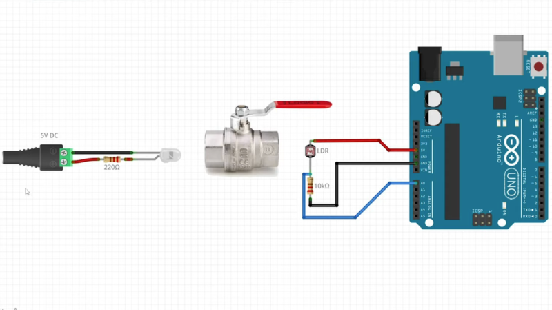
The test hardware setup shown below is built up from my standardized prototyping mini-circuits (see this previous article) and the software used is found at the end of this article.
A small 5mW red laser is directly connected to an output pin and can be turned on/off using a tact switch connected to input pin.
The LDR/LED sensors are in turn connected to a third input pin and sampled by the software. The Arduino board’s bult-in LED is used to indicate the binary sensor output and the corresponding analog values are written to the serial monitor.
The LED had a few shortcomings in this application. The analog range was relatively small (260 to 140) making it tricky to find the on/off threshold. The sensor values read also jumped around quite a bit, so each reading was actually the average of multiple reads with senor recovery delays between each reading.
The LDR performed the best for this application. The sensor was 100% reliable, with the analog values reported between 1000 (exposed to the laser) and 100 (dark). This large range makes it easy to convert to an on/off signal. The sensor could also be read in one operation and requires minimal software additional hardware to use.
Test Code
// Test Laser Tripwire
//
// Test laser sensor types
// Switch off the built-in LED when the laser is blocked
//
// MD_UISwitch from https://github.com/MajicDesigns/MD_UISwitch or Arduino Library Manager


#include <MD_UISwitch.h>

#define TEST_LDR 1
#define TEST_LED 0

const uint8_t PIN_LASER = 12;
const uint8_t PIN_DETECT = A0;
const uint8_t PIN_SWITCH = 3;

MD_UISwitch_Digital sw(PIN_SWITCH); // laser toggle switch

void setup(void)
{
  Serial.begin(57600);
  Serial.print(F("\n[Laser Test]"));
  pinMode(PIN_LASER, OUTPUT);
  pinMode(PIN_DETECT, INPUT);
  pinMode(LED_BUILTIN, OUTPUT);
  sw.begin();
}

#if TEST_LDR
const uint16_t threshold = 200;

inline uint16_t readSensor(void)
{
  return(analogRead(PIN_DETECT));
}
#endif

#if TEST_LED
// LED is in circuit with anode in the PIN_DETECT and gnd to ground
const uint16_t threshold = 160;
const uint8_t samples = 20;
const uint16_t recovery = 2;

uint16_t readSensor(void)
{
  uint32_t sens = 0;

  for (uint8_t i = 0; i < samples; i++) // remember the lowest value out of many readings
  {
    sens += analogRead(PIN_DETECT);
    delay(recovery);                 // the sensor needs a delay here to catch its breath
  }
  sens /= samples;

  return(sens);
}
#endif

void loop(void)
{
  // toggle laser on/off with momentary switch
  if (sw.read() == MD_UISwitch::KEY_PRESS)
    digitalWrite(PIN_LASER, digitalRead(PIN_LASER) == LOW ? HIGH : LOW);

  // display the value of the input detected
  uint16_t v = readSensor();

  digitalWrite(LED_BUILTIN, v < threshold ? HIGH : LOW);

  Serial.print(F("\n"));
  Serial.print(v < threshold);
  Serial.print(F("  "));
  Serial.print(v);
}
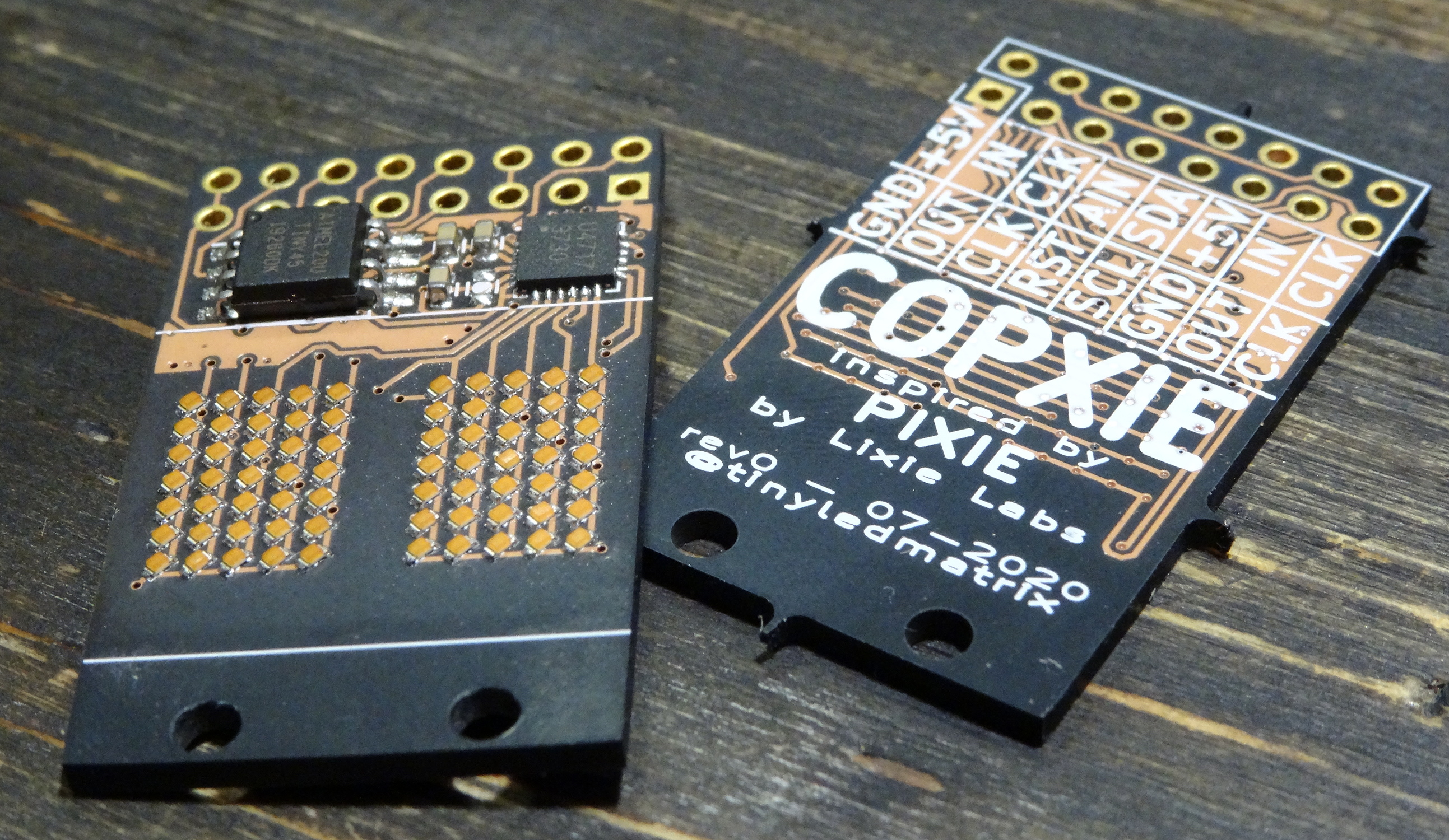
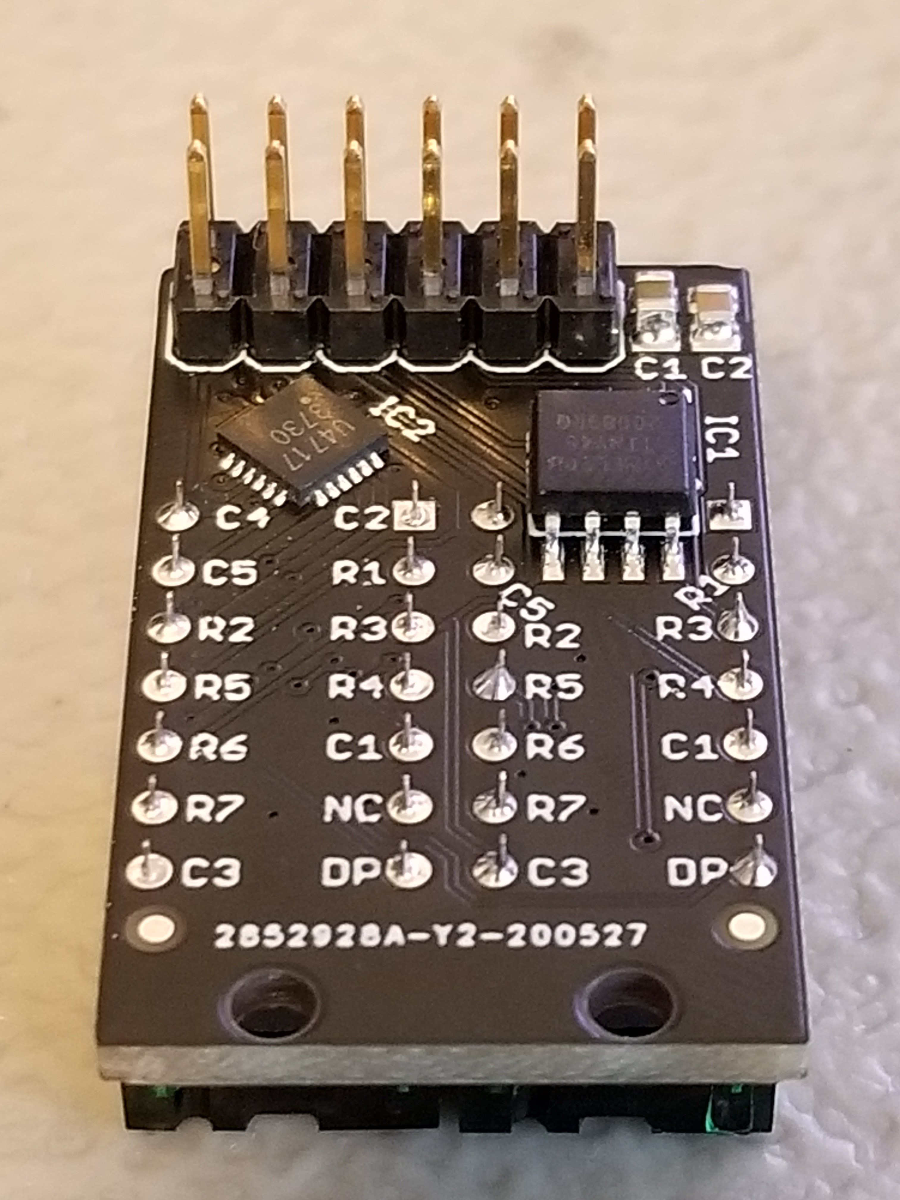
Few things excite a Hackaday staff member more than a glowing LED, so it should be no surprise that combining them together into a matrix really gets us going. Make that matrix tiny, addressable, and chainable and you know it’ll be a hit at the virtual water cooler. We’ve seen [tinyledmatrix]’s work before but he’s back with the COPXIE, a pair of tiny addressable displays on one PCBA.
The sample boards seen at top are a particularly eye catching combination of OSH Park After Dark PCB and mysterious purple SMT LEDs that really explain the entire premise. Each PCBA holds two groups of discrete LEDs each arranged into a 5×7 display. There’s enough density here for a full Latin character set and simple icons and graphics, so there should be enough flexibility for all the NTP-synced desk clocks and train timetables a temporally obsessed hacker could want.
But a display is only as good as it’s SDK, right? The COPXIE is actually designed to be a drop in replacement for a different series of tiny LED matrices, the PIXIE by [Lixie Labs]. To complete the effect the COPXIE runs the same firmware and so has the same feature set. Each module (with two displays) can be controlled with just two pins (data and clock), and chains of more than 12 modules (24 displays) can be strung together. Plus there is a convenient Arduino friendly library which makes control a snap.
To build a COPXIE of your own, check out the schematic linked on the Hackaday.io page, and the layout at the OSH Park share link. Note that it seems like [tinyledmatrix] may not have completely validated these boards, but given there are plenty of photos of them working they seem like a safe bet.
When we last heard from [lixielabs] he was building Nixie tube replacements out of etched acrylic and LEDs. Well he’s moved forward a few decades to bring us the Pixie, a chainable, addressable backpack for tiny LED matrix displays.
Each Pixie module is designed to host two gorgeous little Lite-On LTP-305G/HR 5×7 LED dot matrix displays, which we suspect have been impulse purchases in many a shopping cart. Along with the displays there is a small matrix controller and an ATTINY45 to expose a friendly electrical interface. Each module is designed to be mounted edge to edge and daisy chained out to 12 or more (with two displays each) for a flexible display any size you need. But to address the entire array only two control pins are required (data and clock).
[lixielabs] has done the legwork to make using those pins as easy as possible. He is careful to point out the importance of a good SDK and provides handy Arduino libraries for common microcontrollers and a reference implementation for the Raspberry Pi that should be easy to crib from to support new platforms. To go with that library support is superb documentation in the form of a datasheet (complete with dimensions and schematic!) and well stocked GitHub repo with examples and more.
To get a sense of their graphical capabilities, check out a video of 6 Pixie’s acting as a VU meter after the break. The Pixie looks like what you get when a hacker gets frustrated at reinventing LED dot matrix control for every project and decided to solve it once and for all. The design is clean, well documented, and extremely functional. We’re excited to see what comes next!
Planet Arduino is, or at the moment is wishing to become, an aggregation of public weblogs from around the world written by people who develop, play, think on Arduino platform and his son. The opinions expressed in those weblogs and hence this aggregation are those of the original authors. Entries on this page are owned by their authors. We do not edit, endorse or vouch for the contents of individual posts. For more information about Arduino please visit www.arduino.cc
You are currently browsing the archives for the LED category.


 Each Pixie module is designed to host two gorgeous little
