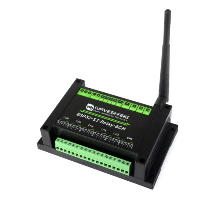
Waveshare ESP32-S3-Relay-6CH is a 6-channel WiFi and Bluetooth relay module based on Espressif Systems ESP32-S3 wireless microcontroller that also supports RS485 control and comes with headers taking Raspberry Pi Pico HATs adding RTC, CAN Bus, RS232, LoRa, sensors, or other features. The relays are rated 250VAC/30VDC up to 10A, the system take 7V to 36V DC input through a terminal block, and can be programmed with Arduino or MicroPython though a USB-C port. It also features a a built-in buzzer, an RGB LED, and is housed in a DIN Rail-mountable ABS case. Waveshare ESP32-S3-Relay-6CH specifications: Wireless module – ESP32-S3-WROOM-1U-N8 by default MCU – ESP32-S3 dual-core Tensilica LX7 up to 240 MHz with 512KB SRAM Storage – 8MB Quad SPI flash Wireless – 2.4 GHz WiFi 4 and Bluetooth LE 5 u.FL connector for external antenna 6x relays via terminal blocks Rating – Up to 10A 250V AC / 30V DC [...]
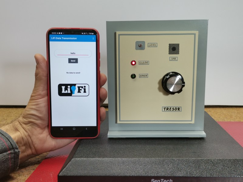
At first blush, this seems horribly insecure. Use a plain old flashlight to open a door? Come on. But the key is in the software. In fact, between the typed-in pass code and the flash of light it generates, this lock kind of has two layers of security.
Here’s what’s going on: inside the accompanying smart phone application, there’s a list of passwords. Each of these passwords corresponds to a flash of light in milliseconds. Enter the correct password to satisfy the Arduino, and the phone’s flashlight is activated for the appropriate number of milliseconds to unlock the door.
As you’ll see in the video below, simply flashing the light manually doesn’t unlock the door, and neither does entering one of the other, bogus passwords. Although it does activate the flashlight each time, they don’t have the appropriate light-time length defined.
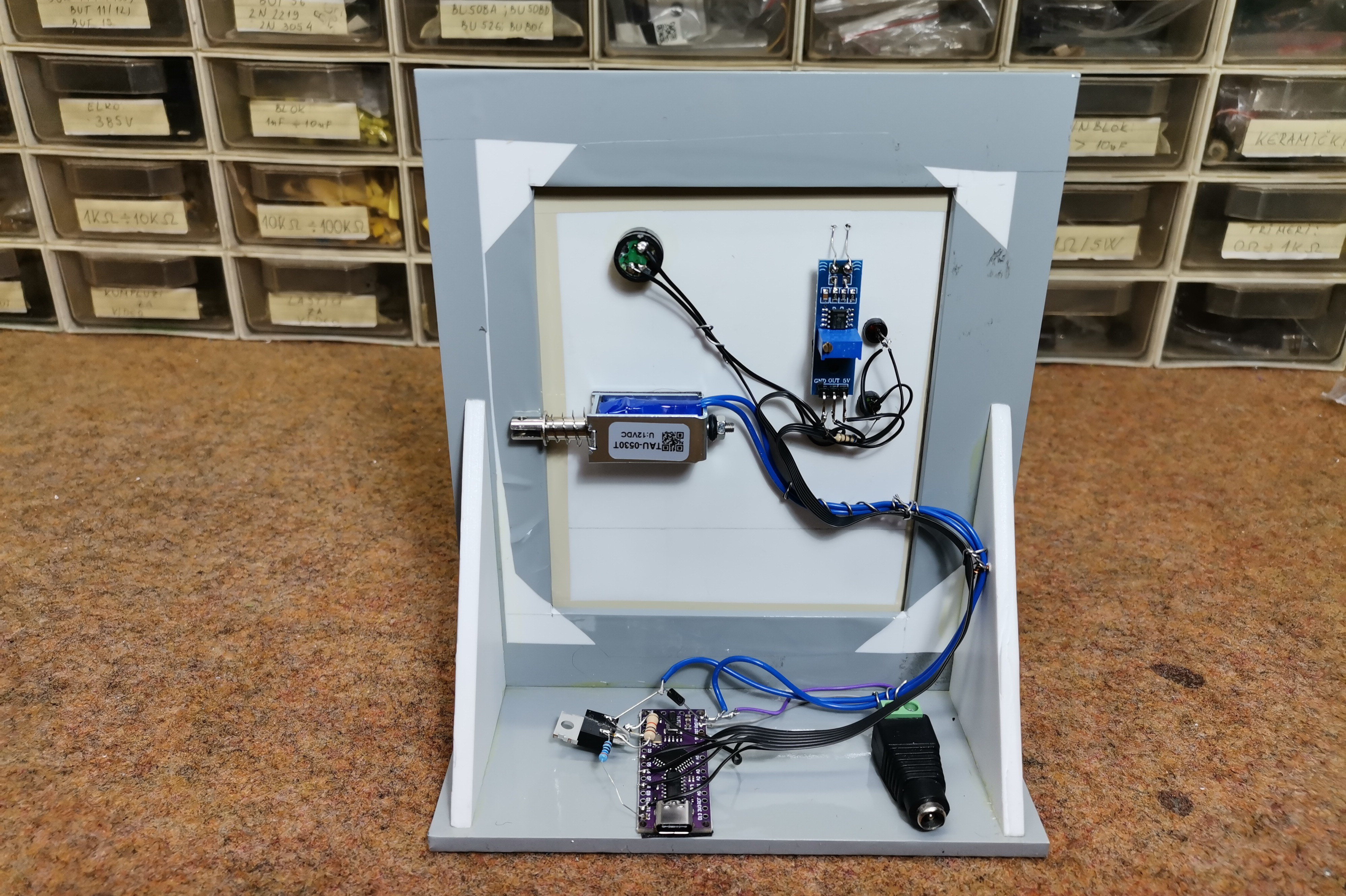
Hardware-wise, there is an Arduino Nano Every in charge of the LDR module that reads the flashlight input and the 12 V relay that unlocks the door. Be sure to check it out it the video after the break.
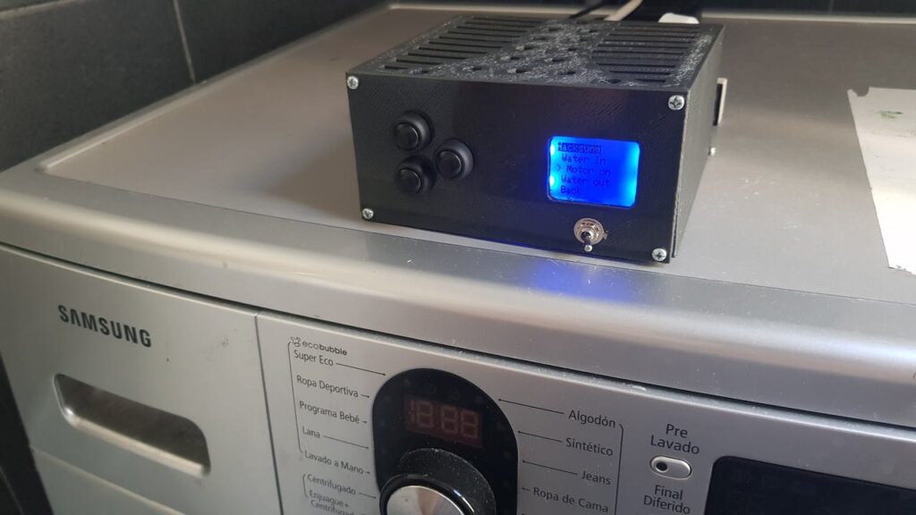
After three short years of use, Roni Bandini’s Samsung washing machine started to act erratically, and several technicians looked at it without really fixing the problem. Bandini then decided to take matters into his own hands and replaced its brains with a MKR WiFi 1010 board, along with four relays and a trio of buttons.
This new system can control the motor and valves to progress through a wash cycle. It also takes advantage of the Arduino’s WiFi abilities to integrate with Telegram, sending a message to the entire family when the laundry is done.
Future goals for the project include varying the motor speed and making it reverse, but so far it’s a brilliant way to keep a large hunk of metal and plastic out of the junkyard. Code is available on GitHub, and print files for the enclosure are up on Thingiverse.
This thing has what plants crave! No, not electrolytes exactly — just water, light, and moisture polling every 30 minutes. We think it’s fitting to take something that once manufactured liquid liveliness for humans and turn it into a smart garden that does the same thing for plants.
So let’s just get this out of the way: the espresso machine was abandoned because it was leaking water from a gasket. [The Plant Bot] cleaned it up, replaced the gasket, and got it brewing, and then it started leaking hot water again from the same gasket. We might have gone Office Space on this beautiful machine at that point, but not [The Plant Bot].
Down in the dirt, there’s a soil moisture sensor that’s polling every 30 minutes. If the moisture level falls below the threshold set appropriately at a life-sustaining 42%, the Arduino is triggered to water the plant through a relay board using the espresso machine’s original pump. If the plant is dry, the machine will pump water for two seconds every minute until the threshold is met. [The Plant Bot] tied it all together with a nice web interface that shows plant data and allows for changes over Bluetooth.
[The Plant Bot] started by disconnecting the heating element, because plants don’t tend to like hot steam. But if the cup warming tray along the top has a separate heating element, it might be neat to reuse it for something like growing mushrooms, or maintaining a sourdough starter if the temperature is right.
It used to be that there wasn’t a problem on the average car that couldn’t be solved with a nice set of wrenches, a case of beer, and a long weekend. But the modern automobile has more in common with a spaceship than those vintage rides of yesteryear. Bristling with sensors and electronics, we’re at the point that some high-end cars need to go back to the dealer for even minor repairs. It’s a dark time for the neighborhood grease monkey.
But for those of us who are more likely to spend their free time working with a compiler than a carburetor, a modern car can be an absolute wonderland. That’s what [TJ Bruno] found when he recently started experimenting with the CAN bus on his 2017 Chevy Cruze. Not only was he able to decode how the different switches and buttons on the dashboard communicated with the vehicle’s onboard systems, he was able to hack in a forward-looking camera that’s so well integrated you’d swear it was a factory option.
The idea started simple enough: using some relays, [TJ] planned on physically switching the video feed going to the Chevy’s dashboard between the stock rear camera and his aftermarket front camera. That’s all well and good, but the car would still only bring up the video feed when the gear selector was put in reverse; not exactly helpful when he’s trying to inch his way into a tight spot. He needed to find a way to bring up the video display when the car was moving forward.
With a PCAN-USB adapter connected to the car’s OBD-II port, he shifted into and out of reverse a few times and noted which messages got transmitted on the network. It wasn’t long before he isolated the proper message, and when he injected it with his laptop, the dashboard display switched over to the backup camera regardless of what gear the car was in. Building on this success, he eventually figured out how to read the status of all the buttons on the car’s dashboard, and programmed an Arduino to listen for the appropriate signals.
The final piece of the puzzle was combing bringing both of these capabilities, so that went the appropriate button was pressed on the dashboard the Arduino would not only send the signal to turn on the video display, but kick the relays over to switch the camera source. Now [TJ] has a front-facing camera that can be called up without having to kludge together some button or switch that would never match the modern styling of the vehicle’s interior.
In the world of ham radio, a “Fox Hunt” is a game where participants are tasked with finding a hidden transmitter through direction finding. Naturally, the game is more challenging when you’re on the hunt for something small and obscure, so the ideal candidate is a small automated beacon that can be tucked away someplace inconspicuous. Of course, cheap is also preferable so you don’t go broke trying to put a game together.
As you might expect, there’s no shortage of kits and turn-key transmitters that you can buy, but [WhisleyTangoHotel] wanted to come up with something that could be put together cheaply and easily from hardware the average ham or hacker might already have laying around. The end result is a very capable “fox” that can be built in just a few minutes at a surprisingly low cost. He cautions that you’ll need a ham license to legally use this gadget, but we imagine most people familiar with this particular pastime will already have the necessary credentials.
The heart of this build is one of the fairly capable, but perhaps more importantly, incredibly cheap Baofeng handheld radios. These little gadgets are likely familiar to the average Hackaday reader, as we discussed their dubious legal status not so long ago. At the moment they are still readily available though, so if you need a second (or third…), you might want to pull the trigger sooner rather than later.
At any rate, in the setup that [WhisleyTangoHotel] has outlined, the Baofeng radio is connected up to an MP3 player which is loaded up with a recording of your message and FCC callsign that plays in a loop. An Arduino and a relay module are then used to key the transmitter automatically by grounding out the microphone connector. As it so happens, the lanyard mount on the Baofeng is a convenient ground point and allows you to hook the whole thing up quickly with alligator clips.
How do you get to sleep at night? For some of us, it can be the most difficult thing we do all day. Worrying about falling asleep and letting other intrusive thoughts in night after night only compounds the problem, as less sleep leads to depression which (for us) leads to even less sleep. We lay there, trapped inside a vortex of churning thoughts, imprisoned in a mind that feels like it’s malfunctioning and half-wishing for a future where instructor-led meditation videos can be beamed to the insides of our eyelids. In the meantime, there is FADing, the Fall Asleep Device.
FADing takes its cues from a relaxation technique that uses light to focus your attention and control your breathing. The light’s intensity waxes and wanes on a schedule designed to get you down from the average eleven breaths per minute to a zen-like six breaths per minute. You surrender to the light, breathing in as it intensifies and breathing out as it fades. There are commercial products that bring this technique to the bedroom, but they aren’t cheap and don’t offer much control. Fail to fall asleep in the prescribed window and you’re back to square one with one more thing to think about: buyer’s remorse.
[Youz] was inspired by these devices but dissatisfied with the price tag and lack of options, so he created his own version with a flexible window of operation that appeals to both back- and side-sleepers. It uses an Arduino Nano and two momentaries to control two LEDs, a relay to hold the power after startup, a 9V, and a diode to protect the Nano. One LED projects on the ceiling, and the other radiates through a slice of acrylic which has been shaded blue. One button is for power, and the other lets you add time by two-minute increments. You can see the build video after the break and then tell us how you’d do it with a 555, a coin cell, and a chunk of uranium glass in the comments.
I have a good background working with high voltage, which for me means over 10,000 volts, but I have many gaps when it comes to the lower voltage realm in which RC control boards and H-bridges live. When working on my first real robot, a BB-8 droid, I stumbled when designing a board to convert varying polarities from an RC receiver board into positive voltages only for an Arduino.
Today’s question is, how do you convert a negative voltage into a positive one?
In the end I came up with something that works, but I’m sure there’s a more elegant solution, and perhaps an obvious one to those more skilled in this low voltage realm. What follows is my journey to come up with this board. What I have works, but it still nibbles at my brain and I’d love to see the Hackaday community’s skill and experience applied to this simple yet perplexing design challenge.
The Problem
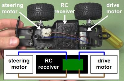
RC toy truck and circuit with no common
I have an RC receiver that I’ve taken from a toy truck. When it was in the truck, it controlled two DC motors: one for driving backwards and forwards, and the other for steering left and right. That means the motors are told to rotate either clockwise or counterclockwise as needed. To make a DC motor rotate in one direction you connect the two wires one way, and to make it rotate in the other direction you reverse the two wires, or you reverse the polarity. None of the output wires are common inside the RC receiver, something I discovered the hard way as you’ll see below.
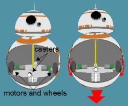
I wasn’t using the RC receiver with the toy truck. I extracted it from the truck and was using it to control my BB-8 droid. My BB-8 droid has two motors configured as what in the BB-8 builders world is called a hamster drive, though is more widely known as a tank drive or differential drive (see the illustrations). Rotate both wheels in the same direction with respect to the droid and the droid moves in that direction. Reverse both wheels and it drives in the opposite direction. Make the wheels rotate in opposite directions and it turns on the spot.
The big picture – RC to drill motors
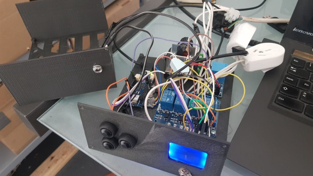
The motors in my BB-8 are drill motors and are controlled by two H-bridge boards. An Arduino does pulse width modulation to the H-bridge boards for speed control, and controls which direction the motors should turn. Finally, the RC receiver is what tells the Arduino what to do. But a converter board, the subject of this article, is needed between the RC receiver and the Arduino. Note that the Arduino is necessary also for countering when the BB-8 droid wobbles and for synchronizing sounds with the movement, but those aren’t addressed here.
Since there are two motors and two directions for each motor, the RC receiver needs to control four pins on the Arduino to make the two drill motors behave as follows: motor 1/clockwise, motor 1/counterclockwise, motor 2/clockwise, motor 2/counterclockwise. And whatever voltages the receiver puts on those pins has to be relative to the Ardunio’s ground.
And herein lies the problem. The Arduino expects positive voltages with respect to its ground on all those pins. So I needed a way to map the RC receiver’s two sets of motor control wires, which can have either positive or negative voltages across them, to the Arduino pins which only want positive voltages. And remember, none of those RC receiver wires are common inside the receiver.
My Fumbling First Approach
Now, keep in mind, electronics is a general interest of mine and except for what we were taught in high school physics class, I’m self-taught. That means I’ve “read ahead” but much of my knowledge has been determined by what projects I’ve done. So I have gaps in my knowledge. I’d never turned negative voltages into positive before. It sounded simple enough. Searching online didn’t help though. The closest I got was in two old posts in forums where the answers were “It’s easy to do. I can do it with a single resistor.” But there was no further explanation and I didn’t ask my own question anywhere at that point.
Using a transistor
Instead I came up with my own approach with just one set of wires from the RC receiver first. The wires coming from the receiver were blue and brown and could have either polarity depending on which way the receiver is being told to rotate the motor: clockwise or counterclockwise. That meant I needed two diodes to create two possible paths for the different polarities the brown wire could be: positive or negative. I then added a battery for the one path that was negative, to turn it into a positive.
Next, I put a PNP transistor between the positive of the battery and the receiver. With no signal from the RC transmitter, the transistor’s base is negative with respect to the emitter, but not enough to turn the transistor on. That’s because the battery’s negative is connected to the receiver’s blue wire and since there’s no signal from the transmitter, the brown wire is also at the same potential as the blue wire, and with battery negative.
The idea was that when the transmitter sent a signal to make that brown wire negative with respect to the blue wire, it would become even more negative and turn on the PNP transistor. A positive signal would then go from the battery, through the transistor to the Arduino.
The most obvious problem was that the Arduino wanted to see 3 volts to register as a HIGH input, meaning the battery would have to be at least 3 volts and so even with no signal from the transmitter, that would be -3 volts to the transistor, turning it on when it wasn’t supposed to be on.
Using A Relay Instead
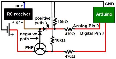
Using a relay
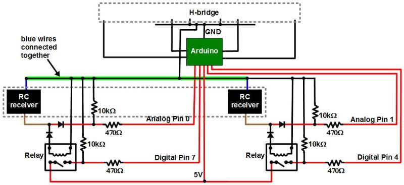
And so I immediately thought of using a relay instead. I’d use the current running through the negative path to energize the relay, closing a switch that was completely independent of the RC receiver. The Arduino has a 5V output pin, so I made that switch close a circuit between the 5V pin and the Arduino’s pin 7, giving pin 7 the needed positive voltage.
The 1 in the circle in the schematic shows where I wanted to put a resistor in order to limit the current going through the relay’s coil. However, I tried with resistors all the way down to 4.7 ohms but the coil didn’t have enough current to close the switch. With no resistor, it worked and the current was 70mA. The relay’s coil was rated for 3V/120mA so I left it.
Using a relay did seem very heavy-handed, but it was the only solution I could come up with and I already had the relay in stock.
The next step was to add a second relay, doing the same for the second set of wires coming from the RC receiver for the second motor.
No Common In The Receiver
Schematic with common blue RC wires
But the behavior was seemingly sporadic. And keep in mind that there was a whole dual H-bridge circuit that was also connected to the Arduino’s ground. I’d worked with relays a lot before, and the RC receiver came from a commercially made and functional toy so I had no reason to suspect that. On the other hand, I’d made the H-bridge circuit from scratch since I already had most of the parts, and I was new to H-bridges and MOSFETs. So at first I spent a good two weeks of spare time thinking my problem was with the H-bridge and drill motor side. I’m sure we’ve all experienced the same blindness, thinking the most likely culprit is the part you had a hand in.
But at some point I disconnected the H-bridge and tested just the RC receiver circuit, watching the voltages at the Arduino pins while I remotely turned on both “motors” in both directions in all combinations (no motors were connected at the time though). The only odd behavior I saw was when I turned the motors on in opposite directions.
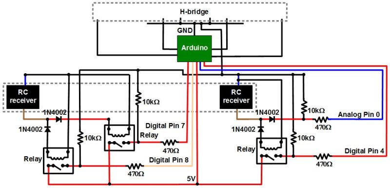
Notice in the schematic that I’d connected together both blue wires coming from the RC receiver. Up to that point I’d been assuming that the blue wires were common inside the receiver and that it was only the brown wires that switched from positive to negative with respect to the blue wires. From the behavior I was seeing it looked like both wires were switching polarity, possibly around some other internal common reference.
Finished RC-to-Arduino converter schematic
So I added a third relay on one of the positive paths of one of the sets of wires. That meant the corresponding blue wire no longer needed to be grounded, keeping both of the receiver’s blue wires separate. Note that I didn’t bother putting in a fourth relay for the remaining positive path, and it turned out to not be necessary. At that point the circuits worked great and continue to do so.
The Ask
And so I ask, is there a better way to convert the RC receiver output to something the Arduino can use? Relays require power, so it would be nice if there was a solution that didn’t require any extra power. My relay solution seems very early 1900s. Or maybe it’s a good solution after all, but just one of many. Let us know in the comments below.
arduino, Relay, RFComments Off on DIY 433MHz RF Receiver and 4 x SPDT Relay Shield
by electro-labs.com:
You are planning to use Arduino in your project but you need some kind of remote control functionality. A standalone Arduino won’t provide what you need but this DIY shield may be a good solution for you. It includes a 433.92Mhz RF receiver which lets you send commands to Arduino wirelessly and four SPDT relays which can be used for switching purposes.
Each relay is capable of switching up to 10A @ 250VAC so they can be used to control mains powered devices. There are four LEDS indicating the status of the relays. The terminal blocks on the shield lets you easily connect the devices you will control.
The RF receiver is a module that can be found in the market easily. It is directly soldered to the shield and runs at 4800bps. The board has an antenna input which lets you solder your custom antenna to increase the wireless range.
DIY 433MHz RF Receiver and 4 x SPDT Relay Shield - [Link]
Planet Arduino is, or at the moment is wishing to become, an aggregation of public weblogs from around the world written by people who develop, play, think on Arduino platform and his son. The opinions expressed in those weblogs and hence this aggregation are those of the original authors. Entries on this page are owned by their authors. We do not edit, endorse or vouch for the contents of individual posts. For more information about Arduino please visit www.arduino.cc
You are currently browsing the archives for the Relay category.