Posts | Comments

Planet Arduino

Archive for the ‘hall effect’ Category

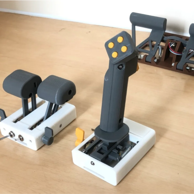
We have seen quite a few DIY joystick designs that use Hall effect sensors, but [Akaki]’s controller designs (YouTube video, embedded below) really make the most of 3D printing to avoid the need for any other type of fabrication. He’s been busy using them to enhance his Microsoft Flight Simulator 2020 experience, and shares not just his joystick design, but makes it a three-pack with designs for throttle and pedals as well.

Hall effect sensors output a voltage that varies in proportion to the presence of a magnetic field, which is typically provided by a nearby magnet. By mounting sensors and magnets in a way that varies the distance between them depending on how a control is moved, position can be sensed and communicated to a host computer. In [akaki]’s case, that communication is done with an Arduino Pro Micro (with ATmega32U4) whose built-in USB support allows it to be configured and recognized as a USB input device. The rest is just tweaking the physical layouts and getting spring or elastic tension right. You can see it all work in the video below.

Hall effect sensors have featured in DIY joystick builds, but for something as delightful as it is different, don’t miss this fantastic high-speed magnetic imager based on them.

Laundry. It’s one of life’s inescapable cycles, but at least we have machines now. The downside of this innovation is that since we no longer monitor every step — the rock-beating, the river-rinsing, the line-hanging and -retrieving — the pain of laundry has evolved into the monotony of monitoring the robots’ work.

[Adam] shares his wash-bots with roommates, and they aren’t close enough to combine their lights and darks and turn it into a group activity. They needed an easy way to tell when the machines are done running, and whose stuff is even in there in the first place, so [Adam] built a laundry machine monitor that uses current sensing to detect when the machines are done running and sends a text to the appropriate person.

Each machine has a little Hall effect-sensing module that’s carefully zip-tied around its power cable. The signal from these three-wire boards goes high when the machine is running and low when it’s not. At the beginning of the load, the launderer simply presses their assigned button on the control box, and the ESP32 inside takes care of the rest.

Getting a text when your drawers are clean is about as private as it gets. Clean underwear, don’t care? Put it on a scrolling marquee.

There are plenty of PC joysticks out there, but that didn’t stop [dizekat] from building his own. Most joysticks mechanically potentiometers or encoders to measure position. Only a few high-end models use Hall effect sensors. That’s the route [dizekat] took.

Hall effect sensors are non-contact devices which measure magnetic fields. They can be used to measure the position and orientation of a magnet. That’s exactly how [dizekat] is using a trio of sensors in his design. The core of the joystick is a universal joint from an old R/C car. The center section of the joint (called a spider) has two one millimeter thick disc magnets glued to it. The Hall sensors themselves are mounted in the universal itself. [Dizekat] used a small piece of a chopstick to hold the sensors in position while he found the zero point and glued them in. A third Hall effect sensor is used to measure a throttle stick positioned on the side of the box.

An Arduino micro reads the sensors and converts the analog signal to USB.  The Arduino Joystick Library by [Matthew Heironimus] formats the data into something a PC can understand.

While this is definitely a rough work in progress, we’re excited by how much [dizekat] has accomplished with simple hand tools and glue. You don’t need a 3D printer, laser cutter, and a CNC to pull off an awesome hack!

If you think Hall effect sensors are just for joysticks, you’d be wrong – they work as cameras for imaging magnetic fields too!

It is pretty easy to go to a big box store and get a digital speedometer for your bike. Not only is that no fun, but the little digital display isn’t going to win you any hacker cred. [AlexGyver] has the answer. Using an Arduino and a servo he built a classic needle speedometer for his bike. It also has a digital display and uses a hall effect sensor to pick up the wheel speed. You can see a video of the project below.

[Alex] talks about the geometry involved, in case your high school math is well into your rear view mirror. The circumference of the wheel is the distance you’ll travel in one revolution. If you know the distance and you know the time, you know the speed and the rest is just conversions to get a numerical speed into an angle on the servo motor. The code is out on GitHub.

Granted, reading a magnet, keeping time, and driving a servo isn’t exactly cutting edge. On the other hand, it made us think about what other kinds of outputs you could drive. We haven’t seen a nixie tube speedometer (well, not on a bicycle, anyway), for example. Or maybe one built with mechanical flip numbers like an old clock.

We have seen some with Arduinos and lots of LEDs (although, again, not really for a bicycle). This speedometer might still be our favorite, though.


Filed under: Arduino Hacks, transportation hacks


  • Newsletter

    Sign up for the PlanetArduino Newsletter, which delivers the most popular articles via e-mail to your inbox every week. Just fill in the information below and submit.

  • Like Us on Facebook